PairGain HIGAIN HLU-319 Manual
Hide thumbs
Also See for HIGAIN HLU-319:
- Manual (72 pages) ,
- Quick installation manual (20 pages) ,
- Manual (56 pages)
Table of Contents
Advertisement
Quick Links
Model
HLU-319
E
NGINEERING
H
G
L
I
AIN
INE
List Number
5
HLU-319
H G
L
M
A
R
G
I
N
(dB)
M
O
D
E
B
R
R
G
C
L
V
I
N
E
B
R
X
G
M
L
T
I
N
E
R
S
2
3
2
P
G
T
AIR
AIN
ECHNOLOGIES
S
ERVICES
™150-319-105-02M¨
S
150-319-105-03
ECTION
U
NIT
Part Number
150-1140-05
HD
I AIN
5
SETUP
S
E
L
STATUS
, I
.
NC
T
P
ECHNICAL
RACTICE
CLEI Code
T1L2B20AAA
Advertisement
Table of Contents

Related Manuals for PairGain HIGAIN HLU-319


Summary of Contents for PairGain HIGAIN HLU-319
- Page 1 Model List Number Part Number CLEI Code HLU-319 150-1140-05 T1L2B20AAA HLU-319 I AIN (dB) SETUP STATUS ECHNOLOGIES NGINEERING ERVICES ECHNICAL RACTICE ™150-319-105-02M¨ 150-319-105-03 ECTION...
- Page 2 PairGain and HiGain are registered trademarks of PairGain Technologies, Inc. Information contained in this document is company private to PairGain Technologies, Inc., and shall not be modified, used, copied, reproduced or disclosed in whole or in part without the written consent of PairGain.
- Page 3 Check the packing list to ensure complete and accurate shipment of each listed item. If the shipment is short or irregular, contact PairGain as described in the Warranty located on the inside back cover. If you must store the equipment for a prolonged period, store the equipment in its original container.
- Page 4 Inspecting Shipment 150-319-105-03, Revision 03 April 21, 1999 HLU-319 List 5...
-
Page 5: Table Of Contents
150-319-105-03, Revision 03 Table of Contents ABLE OF ONTENTS Overview ____________________________________________________________________________ 1 Features ..............................1 Product Enhancements ......................1 Standard Features ........................1 Compatibility .............................2 Applications ............................2 HiGain Doubler Applications ....................2 Personal Communications System Applications ..............3 Front Panel __________________________________________________________________________ 4 Installation___________________________________________________________________________ 8 Verification ............................9 Verification without a Downstream Device ................9 Verification with a Downstream Device ................9 Provisioning .............................10... - Page 6 Table of Contents 150-319-105-03, Revision 03 Troubleshooting _____________________________________________________________________ 37 System Alarms..........................37 Alarm Option for DLC Feed ..................... 38 Retiring System Alarms ....................38 Self Test ..........................38 Loopback Operation ........................38 Generic Loopback Code (GNLB) ..................38 Addressable Repeater Loopback Functions ..............38 Initiating Manual Loopback Sessions ................
- Page 7 150-319-105-03, Revision 03 List of Figures IST OF IGURES Figure 1. HLU-319 List 5 Front Panel ......................4 Figure 2. Installing the HLU-319 into a Shelf ....................8 Figure 3. Maintenance Terminal Main Menu .....................14 Figure 4. System Spans ..........................15 Figure 5. Span Status Screen: No Doubler....................16 Figure 6.
- Page 8 List of Tables 150-319-105-03, Revision 03 IST OF ABLES Table 1. Front Panel Description......................... 5 Table 2. Front Panel Display Messages ...................... 6 Table 3. Navigational Keys on the Maintenance Terminal............... 13 Table 4. Maintenance Terminal Screens ....................14 Table 5. Span Status Fields and Descriptions ...................
-
Page 9: Overview
Overview VERVIEW ® ® The PairGain HiGain HLU-319 List 5 is the Central Office (CO) side of a repeaterless T1 transmission system. When used in conjunction with a HiGain Remote Unit (HRU), the system provides 1.544 Mbps transmission on two unconditioned copper pairs over the full Carrier Service Area (CSA) range. The CSA includes loops up to 12,000 feet of 24 AWG or 9,000 feet of 26 AWG wire, including bridged taps. -
Page 10: Compatibility
Overview 150-319-105-03, Revision 03 • Selectable loopback activation codes • Network Management and Administration (NMA) interface • Lightning and power cross protection on HDSL interfaces • Full duplex 2B1Q HDSL transmission on two pairs at 784 kbps • Margin threshold alarm OMPATIBILITY The HLU-319 List 5 is designed to mount in 3192 mechanics shelves. -
Page 11: Personal Communications System Applications
150-319-105-03, Revision 03 Overview These extended ranges are only available when using the HDU-409, HDU-404 or HDU-407 micro-doublers with the HRU-411 or HRU-402. Older doublers (HDU-451, HDU-439 and HDU-437) cannot be used in circuits with more than two doublers in any line or local power system. For compatibility guidelines on mixing newer doublers with older HRU and HLU models, refer to “HiGain Doubler Circuit Deployment”... -
Page 12: Front Panel
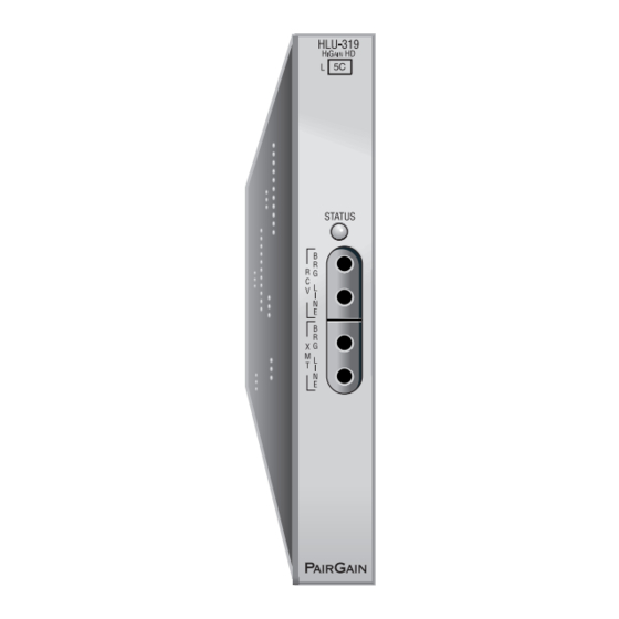
Front Panel 150-319-105-03, Revision 03 RONT ANEL The HLU-319 List 5 front panel is shown is Figure 1. The front panel components are described in Table 1 on page Figure 1. HLU-319 List 5 Front Panel April 21, 1999 HLU-319 List 5... -
Page 13: Table 1. Front Panel Description
150-319-105-03, Revision 03 Front Panel Table 1. Front Panel Description Front Panel Feature Function Front panel display Displays four-character status, provisioning, and alarm system messages. The front panel display illuminates when power is initially applied. To conserve power the display only remains on for 4 minutes. -
Page 14: Table 2. Front Panel Display Messages
Front Panel 150-319-105-03, Revision 03 Table 2. Front Panel Display Messages Message Full Name Description ALARM MESSAGES Alarm CutOff A system alarm has occurred, and has been retired to an ACO condition by pressing the SEL button on the HLU front panel. ALRM Alarm Condition Exists A system alarm condition is in effect. - Page 15 150-319-105-03, Revision 03 Front Panel Table 2. Front Panel Display Messages (Cont.) Message Full Name Description FERR Framing Bit Error Occurred Framing bit error occurred at HLU T1 input. Frame: SF, ESF, UNFR, NONE Defines the type of frame pattern being received from the DSX-1. Displayed during System Settings review mode.
-
Page 16: Installation
Upon receipt of the equipment, visually inspect the contents for signs of damage. If the equipment has been damaged in transit, immediately report the extent of damage to the transportation company and to PairGain Technologies. Figure 2. Installing the HLU-319 into a Shelf When installing an HLU in a chassis, be sure to wear an antistatic wrist strap. -
Page 17: Verification
150-319-105-03, Revision 03 Installation ERIFICATION Once the HLU-319 is installed, verify that it is operating properly. To do this, you need to monitor the following: • Status LED • Status messages reported by the front panel display (see Table 2 on page Verification without a Downstream Device If there is no downstream device installed: Verify that the HLU powers up. -
Page 18: Provisioning
Installation 150-319-105-03, Revision 03 ROVISIONING Refer to “Provisioning” on page 11 for information about using the MODE and SEL buttons or the Maintenance Terminal screens to configure the HLU. While the MODE and SEL buttons can be used to manually accomplish some provisioning tasks, such as setting system options, the Maintenance Terminal screens (available when you connect a PC to the craft port) can handle all provisioning tasks. -
Page 19: Provisioning
150-319-105-03, Revision 03 Provisioning ROVISIONING This is a reference section for HLU provisioning. There are two methods for provisioning the HLU-319 List 5: • Use the MODE and SEL buttons on the front panel of the HLU to: – set system options –... -
Page 20: Resetting To Factory Default Values
Provisioning 150-319-105-03, Revision 03 Resetting to Factory Default Values All user options (Table 8 on page 21) can be set to the factory default values using the MODE and SEL buttons. To set the user options to their default values: Press the SEL button for 6 seconds until the following message appears: DFLT NO Press the SEL button while the DFLT NO message is displayed. -
Page 21: Using A Maintenance Terminal
150-319-105-03, Revision 03 Provisioning SING A AINTENANCE ERMINAL Connecting to a Maintenance Terminal The craft port on the front panel allows you to connect the HLU-319 to a maintenance terminal (ASCII terminal or PC running a terminal emulation program). Once connected to a maintenance terminal, you can access the maintenance, provisioning, and performance screens. -
Page 22: Figure 3. Maintenance Terminal Main Menu
Provisioning 150-319-105-03, Revision 03 Maintenance Terminal Main Menu Figure 3 shows the Maintenance Terminal Main Menu from which you can access system administration screens. The function of each screen selection is listed in Table 4. To access a screen, type the letter shown next to the menu item. -
Page 23: Using The Maintenance Terminal Screens
150-319-105-03, Revision 03 Provisioning Selecting a Maintenance Terminal Function To perform a function within the Maintenance Terminal screens, you can: • Press the key indicated to the left of the selection. • Press the letter in parenthesis for the parameter to be changed. System Spans As shown in Figure... -
Page 24: Figure 5. Span Status Screen: No Doubler
Provisioning 150-319-105-03, Revision 03 Span Status Screen without Doublers SPAN STATUS TIME: 12:06:04 Circuit ID#: DATE: 04/06/99 ALARMS: NONE LOOPBACK: OFF POWER LEVEL: LOW HDSL-1 HDSL-2 HDSL-1 HDSL-2 cur/min/max cur/min/max cur/min/max cur/min/max MARGIN: 23/23/23 23/21/23 24/20/25 24/21/24 PULSE ATTN: INS LOSS: 24 HOUR ES: 00010 00008... -
Page 25: Table 5. Span Status Fields And Descriptions
150-319-105-03, Revision 03 Provisioning Table 5 lists the Span Status fields and descriptions. Table 5. Span Status Fields and Descriptions Field Description Time Time of day when Span Status was checked. Date Date when Span Status was checked. Circuit ID# Shows the user-defined circuit ID. -
Page 26: Table 6. Hdsl System Alarms
Provisioning 150-319-105-03, Revision 03 Table 6. HDSL System Alarms Code Name Description LLOS Local Loss of Signal Loss of the DSX-1 input signal. RLOS Remote Loss of Signal Loss of the HRU T1 input signal. LOSW Loss of Sync Word One of the HDSL loops has lost synchronization. -
Page 27: Set Clock
150-319-105-03, Revision 03 Provisioning Set Clock Press from the Maintenance Terminal Main Menu to open the Set Clock screen (Figure SET CLOCK TIME: 00:14:33 DATE: 04/06/99 CIRCUIT ID#: Format: HH:MM MM/DD/YY NEW TIME: NEW DATE: (U)PDATE REMOTE? Figure 7. Set Clock Screen All time information is lost when power is removed. -
Page 28: System Settings
Provisioning 150-319-105-03, Revision 03 System Settings The options set from the System Settings screen are the same as the options set through the HLU-319 front panel Mode and SEL buttons (except for Margin Alarm Threshold and DS0 Blocking, which can only be set at this screen). -
Page 29: Table 8. Hlu-319 List 5 System Settings Screen Options
150-319-105-03, Revision 03 Provisioning Table 8 describes the System Settings screen options and their counterpart codes for the front panel display. Selections in bold typeface are the factory default settings. Table 8. HLU-319 List 5 System Settings Screen Options Front Panel System Settings Display Selection... - Page 30 Provisioning 150-319-105-03, Revision 03 Table 8. HLU-319 List 5 System Settings Screen Options (Cont.) Front Panel System Settings Display Selection Description Screen Options Code Loopback Timeout LBTO NONE Disables automatic time-out cancellation of all loopbacks. Sets automatic cancellation of all loopbacks to 20 minutes after initiation. Sets automatic cancellation of all loopbacks to 60 minutes after initiation.
- Page 31 150-319-105-03, Revision 03 Provisioning Table 8. HLU-319 List 5 System Settings Screen Options (Cont.) Front Panel System Settings Display Selection Description Screen Options Code RLOS Alarm Enables a remote DS1 LOS condition at the input to the HRU to generate an LOS alarm.
- Page 32 Provisioning 150-319-105-03, Revision 03 BER Option The BER option also uses this (BPV/CRC) TEC to generate an Alarm if enabled. The HLU combines the 1-second TEC counts in both directions for the last 60 seconds. It uses this 1-minute Total System Error Count (TSEC) to generate an alarm if it exceeds the selected BER threshold of (1E-6 or 1E-7) as follows: •...
- Page 33 150-319-105-03, Revision 03 Provisioning Margin Alarm Threshold Option To set the Margin Alarm Threshold: Select from the System Settings Main Menu screen. Enter the desired minimum acceptable alarm threshold from the 0 to 15 dB range. This causes a system alarm to occur if either the margin on HDSL Loop 1 (MAL1) or Loop 2 (MAL2) drops below the selected threshold value.
-
Page 34: Loopback Mode Screen
Provisioning 150-319-105-03, Revision 03 If the HLU-319 is used with the HRU-411 to power PCS sites, PWRF option should be set to AUTO. The HLU automatically detects the need to switch to the HIGH power feed made when it receives a request from the HRU to do so. Ground Fault Detect The HLU-319 has a Ground Fault Detect (GFD) circuit which detects a ground or a resistive path to ground on any wire of any loop of any span with a non-zero voltage. -
Page 35: Figure 9. Loopback Menu: No Doubler
150-319-105-03, Revision 03 Provisioning Loopback Menu without Doubler LOOPBACK MENU TIME: 00:15:34 DATE: 04/06/99 CIRCUIT ID#: A. DISABLE LOOPBACKS B. NETWORK LOOP HLU (NLOC) C. NETWORK LOOP HRU (NREM) G. CUSTOMER LOOP HLU (CREM) H. CUSTOMER LOOP HRU (CLOC) (E)xit Figure 9. -
Page 36: Figure 11. Nloc Loopback Mode Reported In The Maintenance Terminal Main Menu
Provisioning 150-319-105-03, Revision 03 Initiating a Loopback To send one of the available loopbacks, press the appropriate letter in the Loopback Menu. The following prompt appears: PLEASE WAIT....A series of dots moves from left to right indicating that the command has been issued. When this process completes, the system returns to the Maintenance Terminal Main Menu. -
Page 37: View Performance Data Screens
150-319-105-03, Revision 03 Provisioning View Performance Data Screens The Performance Data screens (Figure 12 Figure 13 on page 30) show the Errored (ES) and Unavailable Seconds (UAS) for both HDSL loops and each T1 input at 15-minute intervals over a 4-hour time interval. (The ES and UAS data is separated by a slash mark.) Earlier and later data, in 4-hour time periods on different span screens, can be accessed by pressing (Previous) or... -
Page 38: Figure 12. Performance Data Screen: No Doubler
Provisioning 150-319-105-03, Revision 03 Performance Data Screen without Doubler Figure 12 shows a single non-doubler span. This screen shows the Errored and Unavailable Seconds for the HDSL span between the HLU-319 and the HRU. Date: 04/06/99 PERFORMANCE DATA CIRCUIT ID#: ERRORED SECONDS/UNAVAILABLE SECONDS HDSL-1 HDSL-2... -
Page 39: View Performance History Screen
150-319-105-03, Revision 03 Provisioning View Performance History Screen The Performance History screen shows the daily occurrences of ES and UAS over a 31-day period in 24-hour increments. Errored Seconds and Unavailable Seconds for both HDSL loops and each of the two DS1 inputs are listed for the current and previous period. -
Page 40: Figure 15. 31-Day Performance History Screen: Four Doublers (Span 5)
Provisioning 150-319-105-03, Revision 03 Performance History Screen for Doubler Applications The Performance History screen displays information by span when doublers are present. With multiple doublers (up to four), there can be as many as five span screens. Time: 00:26:29 SPAN 5 PERFORMANCE HISTORY - 31 DAY CIRCUIT ID#: ERRORED SECONDS/UNAVAILABLE SECONDS HDSL-1... -
Page 41: View Alarm History Screen
150-319-105-03, Revision 03 Provisioning View Alarm History Screen Press at the Maintenance Terminal Main Menu to open the Alarm History screen. This screen allows you to view alarms that are currently active. In the Alarm History screen (Figure 16 Figure 17 on page 34) the: •... -
Page 42: Figure 16. Alarm History Screen: No Doubler
Provisioning 150-319-105-03, Revision 03 Alarm History Screen without Doubler ALARM HISTORY TIME: 00:11:01 DATE: 04/06/99 CIRCUIT ID#: Type First Last Current Count LOS, DS1-HLU LOS, DS1-HRU SPAN1 LOSW, HDSL1 SPAN1 LOSW, HDSL2 SPAN1 MARGIN L1 SPAN1 MARGIN L2 PWR-SHRT PWR-GND LAST CLEARED: 04/06/99-00:11 (E)xit (C)lear (U)pdate... -
Page 43: View System Inventory Screen
150-319-105-03, Revision 03 Provisioning View System Inventory Screen The System Inventory screen lists the six possible units that can comprise one HiGain circuit: one HLU, one HRU and up to four doublers. The information in the System Inventory Screen is presented as follows: •... -
Page 44: Figure 18. System Inventory Screen: No Doubler
Provisioning 150-319-105-03, Revision 03 System Inventory Screen without Doubler SYSTEM INVENTORY TIME: 18:16:37 DATE: 4/06/99 A. CIRCUIT ID#: UNIT PRODUCT UNIT ID HLU-319 L5 V7.0 NOT REQUIRED B. HRU HRU-402 L1 V1.3 C. DB1 D. DB2 F. DB3 G. DB4 (E)xit Enter the item letter to change the ID Figure 18. -
Page 45: Troubleshooting
150-319-105-03, Revision 03 Troubleshooting ROUBLESHOOTING YSTEM LARMS Table 12 on page 37 lists possible HLU-319 List 5 alarm states. The accompanying front panel message is listed in the Alarm column. More than one alarm condition can exist at any given time, but only one message can be displayed. -
Page 46: Alarm Option For Dlc Feed
Troubleshooting 150-319-105-03, Revision 03 Alarm Option for DLC Feed To improve HiGain compatibility with the switch-to-protect features used in DLC feeder applications, the HLU-319 has an Alarm Pattern Option (ALMP) that allows you to select either an AIS or LOS T1 output payload for the following alarms: •... -
Page 47: Initiating Manual Loopback Sessions
150-319-105-03, Revision 03 Troubleshooting These additions make A1LB identical to A2LB described below. It is given a separate identity to allow future T1E1 enhancements to be added without affecting A2LB. In addition to the SMJK loopback, a HiGain system can be configured for one of five special in-band loopback (SPLB) command sequences. -
Page 48: Loopback Test Procedures
Troubleshooting 150-319-105-03, Revision 03 Setting the Loopback Timeout Option Before initiating a loopback session, verify that the Loopback Time-out option is set to the desired parameter. The Loopback Time-out option is user-selectable from the System Settings screen. To set the time-out option: Select &... -
Page 49: Loopback Configurations
150-319-105-03, Revision 03 Troubleshooting The transmit and receive T1 DSX-1 ports have splitting access jacks and miniature, 210-series, bridging jacks as shown in Figure 1 on page 4. Connecting one cable between the two bridging jacks and another between the two SPAN jacks splits the XMT and RCV and creates metallic loopbacks towards both the DSX-1 and the HLU-319. -
Page 50: Gnlb Loopback Test Procedures
Troubleshooting 150-319-105-03, Revision 03 The more common generic, SPLB inband loopback commands for doubler loopbacks are listed in Table 13. The commands are very specific combinations of either 6 or 7 bits that continuously repeat. All NDUx loopbacks are towards the network. All CDUx loopbacks are towards the customer. Table 13. -
Page 51: A1Lb, A2Lb, And A5Lb Test Procedures
HLU-319 may indicate one more or one less bit error, depending on the test set type and the number of frame bits contained in the block of errored bits. To avoid this uncertainty, PairGain recommends sending the IR commands unframed. - Page 52 Troubleshooting 150-319-105-03, Revision 03 The HLU is now in Logic Loopback. The Loopback Time-out option is user settable to: • NONE (0 minutes) • 20 minutes • 60 minutes • 120 minutes These selections determine the duration of this loopback unless it is overridden by the Time-out Override command or a loop-down command is sent.
-
Page 53: A3Lb And A4Lb Test Procedures
150-319-105-03, Revision 03 Troubleshooting Table 14. Addressable 1, 2, 5 (A1LB, A2LB, A5LB) Repeater Loopback Commands Name Description Code ARMING or NI LPBK (in-band) Arming code 11000 11000 ... ARMING or NI LPBK (ESF Data Link) Arming code 1111(F) 1111(F)0100(4)1000(8) IR LPDN or DISARM (in-band) Disarming code 11100 11100 ... -
Page 54: Table 15. Addressable 3 And 4 (A3Lb And A4Lb) Repeater Loopback Commands
Troubleshooting 150-319-105-03, Revision 03 These selections determine the duration of this loopback, unless it is overridden by the reception of a second identical 16-bit loop-up command before the timer expires. When this time-out override state exists, the only way to loop the HLU-319 down is to issue one of the three loopdown commands listed in Table 15. -
Page 55: Appendix A - Specifications
150-319-105-03, Revision 03 Appendix A - Specifications A - S PPENDIX PECIFICATIONS 784 kbps 2B1Q HDSL Line Code +13.5 dBm ±0.5 dB at 135 Ω HDSL Output 135 Ω HDSL Line Impedance 35 dB at 196 kHz, 135 Ω Maximum Provisioning Loss Line Clock rate Internal “Stratum 4”... -
Page 56: Hdsl Insertion Loss Guidelines
Appendix A - Specifications 150-319-105-03, Revision 03 HDSL I NSERTION UIDELINES Each loop has no more than 35 dB of loss at 196 kHz, with driving and terminating impedances of 135Ω. provides a “loss” guide for the various cable gauges at 196 kHz and 135 Ω. The table applies to the Table 16 HDSL cable pairs between the HLU, HRU, and HDU modules. -
Page 57: Power Consumption With Doublers
150-319-105-03, Revision 03 Appendix A - Specifications Power Consumption with Doublers Table 18 through Table 24 list the power consumed and dissipated by the HLU-319 when it is used with any of the four basic doubler types in the HiGain family. The maximum current drawn by the CO supply is also listed. Table 18 through Table 20... -
Page 58: Table 21. Hlu-319 Power Parameters-Two Doublers (Hdu-451 List 3, 4, 3B Or 4B)
Appendix A - Specifications 150-319-105-03, Revision 03 Table 21 through Table 23 show power parameters for two doubler, line-powered circuits on 9 kft, 26 AWG loops. Table 21. HLU-319 Power Parameters—Two Doublers (HDU-451 List 3, 4, 3B or 4B) HRU CPE 42.5 V Power Heat Dissipation (Watts) 42.5 V Current (mA) -
Page 59: Maximum Power Dissipation
150-319-105-03, Revision 03 Appendix A - Specifications AXIMUM OWER ISSIPATION The Maximum Power Dissipation measures the power that is converted into heat that builds up within the unit. It contributes to the total heat generated in the space around the unit. It is used to determine the maximum number of fully loaded shelves per bay that does not exceed the maximum allowable power dissipation density in watts per square foot to comply with GR-63. -
Page 60: Hlu-319 List 5 Card Connector
The HLU-319 provides a Network Management Control Bus on pin 7 of the card-edge connector. This allows the various PairGain Management System protocols to manage the HLU through the HMU-319 HiGain Management Unit. Whenever the HLU-319 is under management, the MNGD message displays periodically on the front panel display. -
Page 61: System Alarm Output Pin
150-319-105-03, Revision 03 Appendix A - Specifications when the pin 10 signal is activated. Its normally floating output must never be driven above ground or below -80 V. It can sink a current of 10 mA. The HLU-319 does not support the BPV function (Pin E) of normal HD repeaters. -
Page 62: Craft Port
Appendix A - Specifications 150-319-105-03, Revision 03 RAFT Figure 22. RS-232 Craft Port Pinouts April 21, 1999 HLU-319 List 5... -
Page 63: Appendix B - Functional Operation
UNCTIONAL PERATION PairGain HDSL technology provides full-duplex services at standard T1 rates over copper wires between an HLU and an HRU, which comprise one HiGain system. HiGain systems use PairGain 2-Binary 1-Quartenary (2B1Q) HDSL transceiver systems to establish two, full-duplex, 784 kbps data channels between the HLU-319 and a remotely located HDU or HRU. -
Page 64: Appendixc - Compatibility
The HLU-319 List 5 is compatible with the following T1 repeater shelves and associated equipment: • PairGain HMS-317 (28-slot, 23-inch shelf) • PairGain HHS-319 (3-slot, 19-inch horizontal shelf) • PairGain HMS-308 (8-slot remote enclosure) • Charles Ind. #3192 (28-slot connectorized) •... -
Page 65: Table 25. Higain Doubler Deployment Matrix
150-319-105-03, Revision 03 Appendix C - Compatibility All spans are fully CSA-compliant unless otherwise specified. Circuits that use more than one type of doubler are governed by the most limiting doubler rules. For example, if the HDU-451 is used with the HDU-409, use the HDU-451 deployment rules. Table 25. -
Page 66: Appendixd - Service And Support
PairGain Customer Service Group provides expert pre-sales and post-sales support and training for all its products. ECHNICAL UPPORT Technical assistance is available 24 hours a day, 7 days a week by contacting PairGain Customer Service Group at: (800) 638-0031 or (714) 832-9922 Telephone: The 800 telephone support line is toll-free in the U.S. - Page 67 Include the following information, in writing, along with the equipment you are returning: • Company name, address, and the name of a person PairGain can contact regarding this equipment. • The purchase order number provided to Customer Service when the RMA number was requested.
-
Page 68: Appendix E - Glossary
Appendix E - Glossary 150-319-105-03, Revision 03 E - G PPENDIX LOSSARY 2B1Q 2 Binary,1 Quaternary DSX-1 DS1 Cross-connect Frame Alarm Cut Off Equipment Catalog Item Alarm Indicator Signal Enabled ALMP Alarm Pattern ENFT Enable Fractional T1 Alternate Mark Inversion Errored Seconds American Wire Gauge Extended SuperFrame... - Page 69 150-319-105-03, Revision 03 Appendix E - Glossary Network Management and Administration Return Material Authorization NREM Network Remote Loopback SAIS SmartJack AIS NVRAM Non-Volatile Random Access Memory Super Frame Office Repeater Bay SMJK SmartJack Personal Communication Services Signal-to-Noise Ratio Payload SPLB Special Loopback POTS Plain Old Telephone Service...
-
Page 71: Certification And Warranty
Do not try to repair the unit. If it fails, replace it with another unit and return the faulty unit to PairGain for repair. Any modifications of the unit by anyone other than an authorized PairGain representative voids the warranty. - Page 72 Corporate Office 14402 Franklin Avenue Tustin, CA 92780 Tel: (714) 832-9922 Fax: (714) 832-9924 For Technical Assistance: (800) 638-0031...
Need help?
Do you have a question about the HIGAIN HLU-319 and is the answer not in the manual?
Questions and answers