PairGain HLU-319 Manual
Hide thumbs
Also See for HLU-319:
- Manual (72 pages) ,
- Quick installation manual (20 pages) ,
- Manual (67 pages)
Table of Contents
Advertisement
Quick Links
Model
HLU-319
E
NGINEERING
H
G
L
I
AIN
INE
List Number
5D
HLU-319
H G
L
M
A
R
G
I
N
(dB)
M
O
D
E
B
R
R
G
C
L
V
I
N
E
B
R
G
X
M
L
T
I
N
E
R
S
2
3
2
P
G
T
AIR
AIN
ECHNOLOGIES
S
ERVICES
S
150-319-154-04
ECTION
U
NIT
Part Number
150-1140-54
HD
I AIN
5D
SETUP
S
E
L
STATUS
, I
.
NC
T
P
ECHNICAL
RACTICE
CLEI Code
T1L2B30A
Advertisement
Table of Contents
Troubleshooting

Subscribe to Our Youtube Channel
Related Manuals for PairGain HLU-319


Summary of Contents for PairGain HLU-319
- Page 1 Model List Number Part Number CLEI Code HLU-319 150-1140-54 T1L2B30A HLU-319 I AIN (dB) SETUP STATUS ECHNOLOGIES NGINEERING ERVICES ECHNICAL RACTICE 150-319-154-04 ECTION...
- Page 2 Information furnished by PairGain Technologies is believed to be accurate and reliable. However, no responsibility is assumed by PairGain Technologies for its use; nor for any infringement of patents or other rights of third parties which may result from its use.
- Page 3 Check the packing list to ensure complete and accurate shipment of each listed item. If the shipment is short or irregular, contact PairGain as described in the Warranty located inside the back cover. If you must store the equipment for a prolonged period, store the equipment in its original container.
- Page 4 Inspecting the Shipment 150-319-154-04, Revision 04 September 29, 1999 HLU-319 List 5D...
-
Page 5: Table Of Contents
View Span Status Screen ....................14 Span Status Screen without Doublers ..............15 Span Status Screen for Doubler Applications .............15 Set Clock Screen........................18 Set Time ......................18 Set Date .......................18 Update the HRU Time and Date .................18 HLU-319 List 5D September 29, 1999... - Page 6 A5LB Loopback Commands .................... 40 Manual Loopback Session ....................41 Setting the Loopback Time-out Option .............. 41 Initiating a Manual Loopback Session ............... 42 Loopback Test Procedure ........................ 43 General Troubleshooting Tips ..................43 A5LB Test Procedure......................44 September 29, 1999 HLU-319 List 5D...
- Page 7 Power Consumption .........................47 Power Consumption without Doublers................47 Power Consumption with Doublers...................48 Maximum Power Dissipation......................50 Maximum Current Drain........................50 HLU-319 Card-edge Connector.......................51 Network Management Control Bus ...................51 Fuse Alarm ........................51 System Alarm Output ......................52 Craft Port............................53 Appendix B - Functional Operation _____________________________________________________ 54 Timing ..............................55...
- Page 8 150-319-154-04, Revision 04 IST OF IGURES 1. HLU-319 List 5D Front Panel ........................4 2. Installing the HLU-319 into a Shelf ....................... 8 3. Maintenance Terminal Main Menu ......................13 4. System Spans ..............................14 5. Span Status Screen: No Doubler........................15 6.
- Page 9 4. Maintenance Terminal Screens ........................13 5. Span Status Fields and Descriptions.......................16 6. HDSL System Alarms ............................17 7. Loopback Messages............................17 8. HLU-319 System Settings..........................20 9. Loopback Field Messages and Descriptions ....................23 10. Errored and Unavailable Seconds Definitions ....................26 11. Alarm History Fields and Descriptions ......................30 12.
- Page 10 List of Tables 150-319-154-04, Revision 04 September 29, 1999 HLU-319 List 5D...
-
Page 11: Overview
The PairGain HiGain Line Unit HLU-319 List 5D is the Central Office (CO) side of a repeaterless T1 transmission system. When used in conjunction with a HiGain Remote Unit (HRU), the system provides 1.544 Mbps transmission on two unconditioned copper pairs over the full Carrier Service Area (CSA) range. The CSA includes loops up to 12,000 feet of 24 American Wire Gauge (AWG) or 9,000 feet of 26 AWG wire, including bridged taps. -
Page 12: Standard Features
Settings” on page 20 for additional information. OMPATIBILITY The HLU-319 is designed to mount into 3192 mechanics shelves. For a list of compatible shelves, see “Appendix C - Compatibility” on page All generations of HiGain HLU and HRU modules are compatible with each other. To take advantage of the enhanced features of newer HiGain doublers, refer to “HiGain Doubler Circuit Deployment”... -
Page 13: Higain Doubler Applications
For doubler applications, one to four doublers may be used in the HDSL loops between the HLU and HRU. • The HLU-319 can power three doublers and a remote unit (HRU-402 or HRU-411) for a total of four spans. •... -
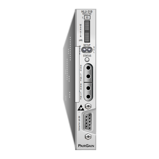
Page 14: Front Panel
Front Panel 150-319-154-04, Revision 04 RONT ANEL The HLU-319 List 5D front panel is shown in Figure 1. The front panel components are described in Table 1 on page 5. For pinout diagrams of the card-edge connector and the craft port, refer to “HLU-319 Card-edge... - Page 15 HDSL acquisition. Fuse Alarm. Flashing red System alarm. Yellow Self Test is in process or an HLU-319 Customer Remote Loopback (CREM) or a Network Local Loopback (NLOC) is in effect. Flashing yellow HLU-319 is in an Armed state. DSX-1 access jacks Provides non-intrusive bridging jack access to (XMT) and from (RCV) the HDSL span at the DSX-1 interface.
-
Page 16: Front Panel Display Messages
Signal from customer is looped back to the customer at the HRU. CREM Customer Remote Loopback Signal from customer is looped back to the customer at HLU-319. NDUn Network Doubler n Loopback Query to initiate loopback at doubler n to network, where n is the number of the doubler. - Page 17 Loop 1 or Loop 2, where n is the number of the span. VER xxxx HLU-319 software version number The software version number appears during the System Settings review mode. Press the MODE button for 3 seconds to display the software version.
-
Page 18: Installation
When installing an HLU in a chassis, be sure to wear an antistatic wrist strap. Avoid touching components on the circuit board. Slide the HLU-319 into the card guides for the desired slot, then push the unit back until it seats firmly in the backplane card-edge connector (Figure Figure 2. -
Page 19: Verification
150-319-154-04, Revision 04 Installation ERIFICATION Once the HLU-319 is installed, verify that it is operating properly. To do this, monitor the following: • Status LED • Status messages reported by the front panel display (Table 2 on page Verification without a Downstream Device If there is no downstream device installed: Verify that the HLU powers up. -
Page 20: Provisioning Requirements
13). This gives you full access to all HLU status, history, inventory, and provisioning screens. No dip switches or jumpers are required to provision the HLU-319 as it contains a Non-volatile Random Access Memory (NVRAM) which stores the system option settings. System option settings are retained if shelf power is lost or if the HLU-319 is unplugged. -
Page 21: Resetting To Factory Default Values
If the system is in a Minor alarm state, the +5 V alarm output level on pin H is removed by pressing the SEL button. This also turns off an Alarm CutOff (ACO) indication. Loopback Modes “Loopback Operation” on page 39 for instructions on using the MODE and SEL buttons to activate loopbacks. HLU-319 List 5D September 29, 1999... -
Page 22: Using A Maintenance Terminal
Connecting to a Maintenance Terminal The craft port on the front panel allows you to connect the HLU-319 to a maintenance terminal (ASCII terminal or PC running a terminal emulation program). Once connected to a maintenance terminal, you can access the maintenance, provisioning, performance, and troubleshooting screens. -
Page 23: Maintenance Terminal Main Menu
The function of each screen selection is listed in Table 4. To access a screen, type the letter shown next to the menu item. HI-GAIN HLU-319 MAINTENANCE TERMINAL MAIN MENU (ver V7.2L-5D) CIRCUIT ID#: A. VIEW SPAN STATUS B. SET CLOCK C. -
Page 24: Selecting A Maintenance Terminal Function
As shown in Figure 4, the HLU can support up to four doublers with five HDSL spans. The Span Status, Performance Data, and Performance History displays up to five screens to depict an HLU-319 system. Figure 4. System Spans SING THE... -
Page 25: Span Status Screen Without Doublers
DS1 STATUS 24 HOUR ES Count: 00000 00017 24 HOUR UAS Count: 00000 00012 Frame type: Code type: AUTOUPDATE OFF (E)xit (C)lear (A)uto(U)pdate (S)pan(1)(2)(3)(4)(5) Figure 6. Span Status Screen: Four Doublers (Span 5) HLU-319 List 5D September 29, 1999... -
Page 26: Span Status Fields And Descriptions
LLOS, RLOS, LAIS, or RAIS. RCV (xxxx) - Signal received (xxxx) at the T1 input to either the HLU or HRU. XMT (xxxx) - Signal transmitted (xxxx) at the T1 output of either the HLU or HRU. September 29, 1999 HLU-319 List 5D... -
Page 27: Hdsl System Alarms
One of the HDSL loops has lost synchronization. LLOS Local Loss of Signal Indicates that no signal is detected at the DSX-1 input to the HLU-319. MAL1 or MAL 2 Margin Alarm 1 or Margin Alarm 2 The margin on the HDSL Loop 1 or Loop 2 has dropped below the threshold (1 to 15 dB) set by the user. -
Page 28: Set Clock Screen
The remote unit date and time is set by using this option. Do one of the following: • Press to update the HRU to the same date and time set for the HLU-319. • Press . (The time and date are not updated.) -
Page 29: System Settings Screen
Enter the option letter to change setting Figure 8. System Settings Screen System settings can also be changed at an HRU that is remotely logged into the HLU-319. Screens viewed at the HRU are nearly identical to those viewed at the HLU, except power settings and remote provisioning settings cannot be changed. - Page 30 Enables an alarm condition to drive the alarm output on pin H to +5 V. DSX-1 Line Code LNCD B8ZS Places both the HLU-319 and HRU into their B8ZS modes. Places both the HLU-319 and HRU into their AMI modes. AIS on SMJK/NREM SAIS Causes the HRU to transmit the AIS signal towards the Customer Interface (CI) when in NREM or SmartJack loopback.
-
Page 31: Bpvt Option
Standard HDSL systems correct T1 BPVs at the input and therefore prevent them from being detected by the DLC terminals to which they are connected. The HLU-319 and its associated remote units remove this limitation and become BPV transparent by detecting and counting input BPVs at each end and then replicating them at the T1 output port of the distant end. -
Page 32: Ber Option
Personal Communication Systems (PCS) sites. If the HLU-319 is used with the HRU-411 to power PCS sites, PWRF option should be set to AUTO. The HLU will automatically detect the need to switch to the HIGH power feed mode when it receives a request from the HRU to do so. -
Page 33: Loopback Mode Screen
For doubler applications, additional loopback selections appear on the screen. • Type to exit and return to the previous menu. Table 9 lists the HLU-319 Loopback field messages and descriptions. Table 9. Loopback Field Messages and Descriptions Messages Full Name Description... -
Page 34: Loopback Menu Without Doubler
H. CUSTOMER LOOP HRU (CLOC) I. CUSTOMER LOOP DOUBLER 1 (CDU1) J. CUSTOMER LOOP DOUBLER 2 (CDU2) K. NETWORK LOOP DOUBLER 3 (NDU3) L. CUSTOMER LOOP DOUBLER 3 (CDU3) (E)xit Figure 10. Loopback Menu: Four Doublers September 29, 1999 HLU-319 List 5D... -
Page 35: Initiating A Loopback
NLOC loopback is in progress). The loopback continues to cycle in the system depending upon your Loopback Timeout setting. The Loopback Menu screen is also available at the HRU connected to the HLU-319, thus allowing all HiGain System loopbacks to be initiated from either end of the circuit. -
Page 36: View Performance Data Screen
HRU craft port. Since the HLU-319 is considered the master module, this clears all performance data screens at both the HLU-319 and the HRU. The RS-232 interface at the HRU does not allow the counters to be cleared. -
Page 37: Performance Data Screen Without Doubler
Provisioning Performance Data Screen without Doubler Figure 12 shows a single non-doubler span. This screen shows the Errored and Unavailable Seconds for the HDSL span between the HLU-319 and the HRU. Time: 00:27:46 PERFORMANCE HISTORY - 31 DAY CIRCUIT ID#:... -
Page 38: View Performance History Screen (7-Day And 31-Day)
Press (7-day) or (31-day) at the Maintenance Terminal Main Menu to open the Performance History screen. This screen shows the ES and UAS for the HDSL loop between the HLU-319 and the HRU. The following options are available: • Press from the Performance History screen to advance through the history screens for the various spans (for doubler applications). -
Page 39: Performance History Screen For Doubler Applications (7-Day And 31-Day)
04/24 04/25 04/26 04/27 04/28 04/29 00001/ 00005/00415 00035/00492 04/30 04/31 00001/ 00002/00002 00004/00014 00006/ 00003/00013 00007/00001 current 00001/ 00005/00415 00035/00492 (E)xit (P)revious (S)pan(1)(2)(3)(4)(5) Figure 15. 31-Day Performance History Screen: Four Doublers (Span 5) HLU-319 List 5D September 29, 1999... -
Page 40: View Alarm History Screen
First and last instance when margin dropped below the established threshold on Loop 2; Current condition, number of alarms. PWR-SHRT Power short condition; Current condition, number of alarms. PWR-GND Power ground condition; Current condition, number of alarms. Last Cleared: Last time Alarm History was cleared. September 29, 1999 HLU-319 List 5D... -
Page 41: Alarm History Screen Without Doubler
09/20/99-00:00 SPAN5 LOSW, HDSL2 09/20/99-00:00 09/20/99-00:00 SPAN5 MARGIN L1 09/20/99-00:00 09/20/99-00:00 SPAN5 MARGIN L2 09/20/99-00:00 09/20/99-00:00 PWR-SHRT PWR-GND LAST CLEARED: 09/20/99-13:49 (E)xit (C)lear (U)pdate (S)pan(1)(2)(3)(4)(5) Figure 17. Alarm History Screen: Four Doublers (Span 5) HLU-319 List 5D September 29, 1999... -
Page 42: System Inventory Screen
• All detected modules have the product number listed. When the HLU-319 loses sync with Span 1, the product types are replaced by the N/A label until sync is reestablished and each module can in turn be reidentified. Only the Circuit ID appears in the other HLU-319 List 5D Maintenance Terminal screens. -
Page 43: System Inventory Screen Without Doubler
Provisioning System Inventory Screen without Doubler SYSTEM INVENTORY TIME: 00:27:59 DATE: 09/20/99 A. CIRCUIT ID: UNIT PRODUCT UNIT ID HLU-319 L5D V7.2 NOT REQUIRED B. HRU HRU-402 L1A V1.3 Remote Unit C. DB1 D. DB2 F. DB3 G. DB4 (E)xit Enter the item letter to change the ID Figure 18. -
Page 44: View Troubleshooting Screen
L(O)S DS1 Unavailable Second Loss of T1 signal at input Alarm Indication Signal Far end LOS, HDSL LOSW, loopbacks or MAL AUTOUPDATE OFF (E)xit (A)uto(U)pdate (H)elp (L)oopbacks Figure 21. Troubleshooting Screen Identifying Circuit Problems September 29, 1999 HLU-319 List 5D... -
Page 45: Troubleshooting With Help
Errors include BPV, framing and CRC L(O)S DS1 Unavailable Second Loss of T1 signal at input Alarm Indication Signal Far end LOS, HDSL LOSW, loopbacks or MAL AUTOUPDATE OFF (E)xit (A)uto(U)pdate (B)ack (L)oopbacks Figure 22. Troubleshooting with Help HLU-319 List 5D September 29, 1999... -
Page 46: Troubleshooting With Margin Values
High insertion loss is the result of a low received HDSL signal. Some causes of high insertion loss: - Long loop - Bridged taps AUTOUPDATE OFF (E)xit (A)uto(U)pdate (B)ack (L)oopbacks Figure 24. Troubleshooting with Insertion Loss Values September 29, 1999 HLU-319 List 5D... -
Page 47: Troubleshooting With Errored Seconds Values
The maximum value can be displayed is 999. Some causes of HDSL unavailable seconds: Shorts, interference, noise Some causes of DS1 unavailable seconds: Loss of Signal AUTOUPDATE OFF (E)xit (A)uto(U)pdate (B)ack (L)oopbacks Figure 26. Troubleshooting with Unavailable Seconds Values HLU-319 List 5D September 29, 1999... -
Page 48: Troubleshooting
Cannot be inhibited. (a) When both HDSL loops lose sync word (LOSW), a system alarm condition exists. However, since the HLU-319 enters a self-test cycling mode, the front panel LED lights yellow instead of red and the SELF TEST message displays instead of the ALRM message. -
Page 49: Alarm Option For Digital Loop Carrier (Dlc) Feed
Alarm Option for Digital Loop Carrier (DLC) Feed To improve HiGain compatibility with the switch-to-protect features used in DLC feeder applications, the HLU-319 has an Alarm Pattern Option (ALMP) that allows you to select either an AIS or LOS T1 output payload for the following alarms: •... -
Page 50: A5Lb Loopback Commands
SmartJack loopback commands. A5LB Loopback Commands A5LB is a special, addressable, repeater loopback mode which is supported by the HLU-319. This loopback mode provides the HiGain system with sophisticated maintenance and troubleshooting tools. The A5LB is patterned... -
Page 51: Manual Loopback Session
• alternate query loopback The A5LB loopback does not block the arming code from exiting the HLU-319 and entering the network. A HiGain system may take longer than normal to respond to inband loopback commands when the framing mode is set to UNFR and the inband commands are set in either SF or ESF mode. -
Page 52: Initiating A Manual Loopback Session
Loopback and Status screens by the annotation HG (HiGain) or PL (Payload) adjacent to the identified loopback. For example, NREM (HG) indicates that the loopback was initiated by the HiGain system. SMJK loopback commands are only activated by inband commands. September 29, 1999 HLU-319 List 5D... -
Page 53: Loopback Test Procedure
DS1 loops to the customer and the local DSX-1 interface. Figure 28 shows the supported loopback configurations. Figure 28. Supported Loopback Configurations General Troubleshooting Tips If trouble is encountered on the DSX-1 interface of the HLU-319, verify that the: • HLU is making a positive connection with its mounting assembly (shelf) connector. •... -
Page 54: A5Lb Test Procedure
To perform the A5LB test procedure: Send the inband Arming and NI LPBK code 11000 to the HLU-319 for at least 5 seconds. Monitor the output of the HLU-319 for the return of the pattern. Return of the pattern indicates one of the following: •... - Page 55 41). If the Time-out Override code 1101-0101-1101-0110 (D5D6) is received after activating a loopback, then the automatic timed expiration of the loopback is inhibited. If this Time-out Override is sent, then the only way to loop the HLU-319 down is to do one of the following: •...
-
Page 56: Appendix A - Specifications
0.625 in. (1.59 cm) Depth: 10 in. (25.4 cm) Weight: 0.45 lb. (.20 kg) Wander (Looped) 0.3 UI maximum (1 UI = 648 ns) WB Jitter (Looped) 0.2 UI maximum NB Jitter (Looped) 0.1 UI maximum September 29, 1999 HLU-319 List 5D... -
Page 57: Hdsl Insertion Loss Guidelines
A Windows-based program, Cable Calculator, may be downloaded from the Customer Site portion of the PairGain Web page at www.pairgain.com. A password is required for access to the Customer Site Web pages. If you don’t have a password, contact your PairGain sales representative. -
Page 58: Power Consumption With Doublers
Table 23 list the power consumed and dissipated by the HLU-319 when it is used with any of the four basic doubler types in the HiGain family. The maximum current drawn by the CO supply is also listed. Table 17... -
Page 59: Power Parameters-Two Doublers (Hdu-451 List 3, 4, 3B Or 4B)
HRU Model No. Power Consumption (Watts) Heat Dissipation (Watts) 42.5 V Current (mA) Typical Maximum Typical Maximum Typical Maximum HRU-402, 3-doubler, N/A (OFF) 22.9 25.2 line-powered HRU-402, 4-doubler, N/A (OFF) 23.7 26.1 local power HLU-319 List 5D September 29, 1999... -
Page 60: Maximum Power Dissipation
The 42.5 V Power Consumption is the maximum total power that the HLU-319 consumes or draws from the shelf power source. This parameter is needed when the HLU-319 is in a location remote to the CO it is serving. It determines the battery capacity required to maintain an 8-hour, stand-by battery reserve for emergency situations. -
Page 61: Hlu-319 Card-Edge Connector
Figure 29. HLU-319 List 5D Card-edge Connector Network Management Control Bus The HLU-319 provides a Network Management Control Bus on pin 7 of the card-edge connector. This allows the various PairGain Management System protocols to manage the HLU through the HiGain Management Unit. -
Page 62: System Alarm Output
The normally floating output of Pin H can connect to pin 1 of the 1184 or 3192-9F Alarm Card in position 29 of the High Density (HD) shelf. • The HLU-319 forces pin H to +5 V (maximum of 10 mA) for a system alarm condition. Pin H then remains at +5 V for the duration of the alarm condition. •... -
Page 63: Craft Port
Appendix A - Specifications RAFT Figure 30 shows the pinout for the craft port connector and its connection to a DB-9 or DB-25 connector on a maintenance terminal. Figure 30. RS-232 Craft Port Pinouts HLU-319 List 5D September 29, 1999... -
Page 64: Appendix B - Functional Operation
UNCTIONAL PERATION PairGain HDSL technology provides full-duplex services at standard T1 rates over copper wires between an HLU and an HRU, which comprise one HiGain system. HiGain systems use PairGain 2-Binary 1-Quartenary (2B1Q) HDSL transceiver systems to establish two, full-duplex, 784 kbps data channels between the HLU-231 and a remotely located HDU or HRU. -
Page 65: Timing
ETECT The HLU-319 has a Ground Fault Detect (GFD) circuit which detects a ground or a resistive path to ground on any wire of any loop of any span with a non-zero voltage. For low (-135 V) applications, such a circuit is active during start-up by applying the bipolar voltage to the loops. -
Page 66: Appendixc - Compatibility
Charles Ind. #340-00 (9- to 11-slot wire wrap) The Charles Ind. 343-00 and 340-00 shelves do not support the HLU-319 System Alarm output on pin H. Also, if slots 1 and 2 of these shelves were wired for the 3408 Fault Locate unit, they must be rewired to accept the HLU-319. - Page 67 (a) HRU-411 applications with I-CPE “on” are limited to single doubler circuits (HDU-404, HDU-407 or HDU-409) using HLU-231, List 8/8A/8D/8E; HLU-319, List 5/5A/5D/5E; and HLU-388 List 5/5A/5D/5E. The HRU-412, HDU-451, HDU-437 and HDU-439 are limited to applications with one and two doublers only.
-
Page 68: Appendixd - Product Support
PairGain Customer Service Group provides expert pre-sales and post-sales support and training for all its products. ECHNICAL UPPORT Technical assistance is available 24 hours a day, 7 days a week by contacting PairGain Customer Service Group at: 800.638.0031 or 714.832.9922 Telephone: The 800 telephone support line is toll-free in the U.S. - Page 69 Pack the equipment in a shipping carton. Write PairGain’s address and the Return Material Authorization (RMA) Number you received from the RMA Department clearly on the outside of the carton and return to: PairGain Technologies, Inc.
-
Page 70: Appendix E - Glossary
High Capacity Digital Service Span Terminating Shelf HiGain Central Office Shelf Total Error Count HDSL High-bit-rate Digital Subscriber Line TLOS Transmit Loss of Signal HiGain Doubler Unit Unavailable Seconds HiGain Line Unit Transmit HiGain Management Shelf September 29, 1999 HLU-319 List 5D... -
Page 71: Certification And Warranty
Do not try to repair the unit. If it fails, replace it with another unit and return the faulty unit to PairGain for repair. Any modifications of the unit by anyone other than an authorized PairGain representative voids the warranty. - Page 72 Corporate Office 14402 Franklin Avenue Tustin, CA 92780 Tel: 714.832.9922 Fax: 714.832.9924 For Technical Assistance: 800.638.0031...
Need help?
Do you have a question about the HLU-319 and is the answer not in the manual?
Questions and answers