PairGain HIGAIN HLU-319 Manual
Hide thumbs
Also See for HIGAIN HLU-319:
- Manual (72 pages) ,
- Quick installation manual (20 pages) ,
- Quick installation manual (20 pages)
Table of Contents
Advertisement
Quick Links
Model
HLU-319
E
NGINEERING
H
G
L
I
AIN
INE
List Number
2E
HLU-319
H G
L
M
A
R
G
I
N
(dB)
M
O
D
E
STATUS
B
R
R
G
C
L
V
I
N
E
B
R
G
X
M
L
T
I
N
E
R
S
2
3
2
P
G
T
AIR
AIN
ECHNOLOGIES
S
ERVICES
™150-319-125-01S¨
S
150-319-125-01
ECTION
U
NIT
Part Number
150-1140-25
HD
I AIN
SETUP
S
E
L
, I
.
NC
T
P
ECHNICAL
RACTICE
CLEI Code
T1L1BH43AA
Advertisement
Table of Contents

Subscribe to Our Youtube Channel
Related Manuals for PairGain HIGAIN HLU-319


Summary of Contents for PairGain HIGAIN HLU-319
- Page 1 Model List Number Part Number CLEI Code HLU-319 150-1140-25 T1L1BH43AA HLU-319 I AIN (dB) SETUP STATUS ECHNOLOGIES NGINEERING ERVICES ECHNICAL RACTICE ™150-319-125-01S¨ 150-319-125-01 ECTION...
- Page 2 PairGain and HiGain are registered trademarks of PairGain Technologies, Inc. Information contained in this document is company private to PairGain Technologies, Inc., and shall not be modified, used, copied, reproduced or disclosed in whole or in part without the written consent of PairGain.
- Page 3 Check the packing list to ensure complete and accurate shipment of each listed item. If the shipment is short or irregular, contact PairGain as described in the Warranty. If you must store the equipment for a prolonged period, store the equipment in its original container.
- Page 4 150-319-125-01, Revision 01 HiGain Line Unit HiGain Remote Unit Loss of Signal LOSW Loss of Sync Word NEBS Network Equipment Building System Network Interface Network Interface Device Network Management Administration NREM Network Remote Loopback POTS Plain Old Telephone System PWRF Power Feed SAIS SmartJack AIS...
-
Page 5: Table Of Contents
150-319-125-01, Revision 01 Table of Contents ABLE OF ONTENTS Product Overview_____________________________________________________________________ 1 HLU-319 Features..........................1 Applications ............................2 Product Description ___________________________________________________________________ 3 Front Panel ............................3 Status LED...........................4 Front Panel Display ......................5 HLU-319 Card-Edge Connectors.......................8 Network Management Control Bus ..................8 Fuse Alarm ..........................8 System Alarm Output Pin....................9 Installation__________________________________________________________________________ 10 Provisioning the HLU-319 _____________________________________________________________ 11... - Page 6 Table of Contents 150-319-125-01, Revision 01 System Settings ..........................20 DS0 Blocking Option......................20 DS1 Line Code Option...................... 21 Margin Alarm Threshold ....................21 HAIS Selections ........................ 22 System Settings Screen Options ..................22 Circuit ID Option..........................26 Loopback Menu..........................26 Loopback Menu: No Doubler ...................
- Page 7 150-319-125-01, Revision 01 Table of Contents Functional Operation _________________________________________________________________ 50 HDSL Line Voltage......................51 Ground Fault Detect ......................52 Power Consumption .........................52 Power Consumption: Without Doublers................52 Maximum Power Dissipation:................52 Maximum Power Consumption: .................52 Maximum Current Drain:..................52 Power Consumption: With Doublers.................53 Compatibility _______________________________________________________________________ 54 T1 Repeater Shelves and Related Equipment ..................54 Doubler Deployment........................55 Product Support _____________________________________________________________________ 56...
- Page 8 Table of Contents 150-319-125-01, Revision 01 viii September 15, 1998 HLU-319 List 2E...
- Page 9 150-319-125-01, Revision 01 List of Figures IST OF IGURES Figure 1. HLU-319 Front Panel........................3 Figure 2. HLU-319 Card-Edge Connectors......................8 Figure 3. Installing the HLU-319 into a Shelf....................10 Figure 4. DB-9 RS-232 I/O Pinouts .......................13 Figure 5. System Spans ..........................14 Figure 6. Maintenance Terminal Main Menu....................15 Figure 7.
- Page 10 List of Tables 150-319-125-01, Revision 01 IST OF ABLES Table 1. HDSL Loss Over Cables..........................2 Table 2. Front Panel Components ..........................4 Table 3. Status LED Descriptions ..........................4 Table 4. HLU-319 Front Panel Display Messages ....................... 5 Table 5. Navigational Keys on the Maintenance Terminal..................14 Table 6.
-
Page 11: Product Overview
RODUCT VERVIEW ® ® The PairGain HiGain HLU-319 List 2E is the Central Office (CO) side of a repeaterless T1 transmission system. When used in conjunction with a HiGain remote unit (HRU), the system provides 1.544 Mbps transmission on two unconditioned copper pairs over the full Carrier Service Area (CSA) range. The HLU-319 can be used in applications with or without HiGain Doubler Units (HDUs). -
Page 12: Applications
Product Overview 150-319-125-01, Revision 01 PPLICATIONS HiGain systems provide a cost-effective, easy-to-deploy method for delivering T1 High Capacity Digital Service (HCDS) over metallic pairs. • The service is deployed over two unconditioned, non-loaded copper pairs, yet it demonstrates a quality that is competitive with fiber optics. -
Page 13: Product Description
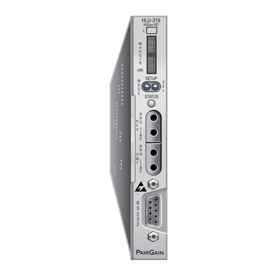
HiGain HD Front panel display System option buttons (dB) Status LED SETUP STATUS Card handle (configuration number and CLEI/ECI bar code on handle) DSX-1 access jacks Craft port PairGain Figure 1. HLU-319 Front Panel HLU-319 List 2E September 15, 1998... -
Page 14: Status Led
Product Description 150-319-125-01, Revision 01 Table 2. Front Panel Components Front Panel Feature Function Front panel display Displays four-character status, provisioning, and alarm system messages. System option buttons (MODE and Permit the user options to be monitored and modified without using a SEL) maintenance terminal. -
Page 15: Front Panel Display
150-319-125-01, Revision 01 Product Description Front Panel Display The front panel display (Figure 1) is used with the MODE and SEL buttons to display system diagnostic messages. Refer to Table 4 for a listing of the four-character messages. The front panel display turns on when power is initially applied to the HLU-319. To conserve power, the display only remains on for five minutes. - Page 16 Product Description 150-319-125-01, Revision 01 Table 4. HLU-319 Front Panel Display Messages (Cont.) Message Full Name Description SIG1 Signal 1 The HLU-319 and the first doubler transceivers are trying to establish contact on loop 1 of span 1. S2L1 Signal 2 Loop 1 The first doubler is trying to establish contact with either the HRU or the second doubler transceivers on loop 1 of span 2.
- Page 17 150-319-125-01, Revision 01 Product Description Table 4. HLU-319 Front Panel Display Messages (Cont.) Message Full Name Description NREM Network Remote Loopback The loopback at HRU (remote) toward network initiated from CO (network) by either the Intelligent Line Repeater (ILR) number 2 code, the HLU-319 front panel Manual Loopback push buttons, the HRU front panel push button, or the maintenance terminal.
-
Page 18: Hlu-319 Card-Edge Connectors
Figure 2. HLU-319 Card-Edge Connectors Network Management Control Bus The HLU-319 provides a Network Management Control Bus on Pin 7 of the card-edge connector. This allows the various PairGain Management System protocols to manage the HLU-319 through the HMU-310 HiGain Management Unit. Fuse Alarm Pin 10 on the card-edge connector is a Fuse Alarm that driven to -48 V whenever its on-board fuse opens. -
Page 19: System Alarm Output Pin
150-319-125-01, Revision 01 Product Description System Alarm Output Pin Pin H on the card-edge connector is the HLU-319 System Alarm output pin. The following notes apply to Pin H: • Pin H replaces the Local Loss of Signal alarm on normal HD (3192) repeaters. •... -
Page 20: Installation
Installation 150-319-125-01, Revision 01 NSTALLATION This product contains static-sensitive components. Be sure to ground yourself properly before touching the HLU-319. To install the HLU-319: Slide the HLU-319 into the card guides for the desired slot, then push the unit back until it touches the backplane card-edge connector and the retaining latch on the front panel opens (Figure Figure 3. -
Page 21: Provisioning The Hlu-319
150-319-125-01, Revision 01 Provisioning the HLU-319 HLU-319 ROVISIONING THE There are two methods for provisioning the HLU-319: • Use the MODE and SEL buttons on the front panel. • Access system settings screens through the Craft port. No dip switches or jumpers are required to provision the HLU-319, as it contains a Non-Volatile RAM (NVRAM) which stores the system option settings. -
Page 22: Displaying System Inventory
Provisioning the HLU-319 150-319-125-01, Revision 01 Displaying System Inventory To scroll through an inventory of system parameters, press the MODE button for three or more seconds. The following parameters are displayed: • HLU-319 software version number • HLU-319 List number •... -
Page 23: Maintenance
150-319-125-01, Revision 01 Maintenance The Craft port is a standard RS-232 (DB-9, female) connector on the front panel. See Figure 4 for pinouts. Figure 4. DB-9 RS-232 I/O Pinouts AINTENANCE This section explains how to navigate through the Maintenance Terminal screens and describes the Main Menu and its various options. -
Page 24: System Spans
Maintenance 150-319-125-01, Revision 01 System Spans As shown in Figure 5, the HLU-319 can support up to two doublers with three HDSL spans. The Span Status, Performance Data, and Performance History may display as many four screens to depict an HLU-319 system. -
Page 25: Initializing The Maintenance Terminal Screens
150-319-125-01, Revision 01 Maintenance NITIALIZING THE AINTENANCE ERMINAL CREENS Press the 63$&(%$5 several times to initiate the autobaud connection and to initialize the Maintenance Terminal screens. AINTENANCE ERMINAL Figure 6 shows the Maintenance Terminal Main Menu, from which you can access eight system administration screens. -
Page 26: View Span Status
Maintenance 150-319-125-01, Revision 01 Table 6. Maintenance Terminal Screens Screen Function See page: View Span Status Provides access to subscreens that allow you to monitor the HDSL line between the HLU-319 and the HRU. Set Clock Allows you to set both the time and the date parameters at the HLU-319, and to update the same settings at the HRU. -
Page 27: Figure 7. Span Status Screen: No Doubler
150-319-125-01, Revision 01 Maintenance SPAN STATUS (HLU/ver1.0-0002: HRU/ver0.0-0000) TIME: 00:15:40 DATE: 02/02/98 Circuit ID#: ALARMS: LAIS LOSW1 LOSW2 LOOPBACK: OFF HDSL-1 HDSL-2 HDSL-1 HDSL-2 cur/min/max cur/min/max cur/min/max cur/min/max MARGIN: PULSE ATTN: PPM OFFSET: 24 HOUR ES: 00005 00003 00006 00006 seconds 24 HOUR UAS: 00086... -
Page 28: Set Clock
Maintenance 150-319-125-01, Revision 01 SPAN STATUS (HLU/ver1.0-0002: HRU/ver0.0-0000) TIME: 00:15:40 DATE: 02/02/98 Circuit ID#: ALARMS: NONE LOOPBACK: HDU1 HDSL-1 HDSL-2 HDSL-1 HDSL-2 cur/min/max cur/min/max cur/min/max cur/min/max MARGIN: 22/00/22 21/00/22 22/21/23 22/20/23 dB PULSE ATTN: PPM OFFSET: 24 HOUR ES: 00001 00003 00012 00010... -
Page 29: Set Time
150-319-125-01, Revision 01 Maintenance All time information is lost when power is removed. The last date, however, is retained in NVRAM and reappears when power is restored. Set Time The cursor defaults to the New Time field. To set the system time, type the hour and minute in the 24-hour format (17(5 of hh:mm:ss (setting the seconds is optional), then press . -
Page 30: System Settings
Maintenance 150-319-125-01, Revision 01 YSTEM ETTINGS The options set from the System Settings menu are the same as the options set using the HLU-319 front panel Mode and SEL buttons. All 14 user options can be set from this menu. Press &... -
Page 31: Ds1 Line Code Option
150-319-125-01, Revision 01 Maintenance All blocked channels are temporarily unblocked for all HiGain system loopback tests. This allows the standard full bandwidth T1 loopback tests to be performed. DS1 Line Code Option The DS1 line code option should always be set to conform to the type of T1 service (AMI or B8ZS) being provided by the HiGain system. -
Page 32: Hais Selections
Maintenance 150-319-125-01, Revision 01 HAIS Selections The HAIS option provides two selections for the T1 transmit outputs at both the HLU-319 and HRU for HDSL loss-of-sync conditions. • 1LP - causes the AIS pattern to be transmitted at both T1 outputs when either of the two HDSL loops experience a loss-of-sync (LOSW) condition or when a margin alarm occurs. - Page 33 150-319-125-01, Revision 01 Maintenance Table 7. HLU-319 System Options (Cont.) System Settings Mode Selection Description Screen Option (S)PECIAL LPBK SPLB GNLB* Configures the HiGain system to respond to the generic (3/4/5/6 in 7) in-band loopback codes. A1LB and A2LB Configures the HiGain system to respond to the Teltrend addressable repeater in-band loopback codes.
- Page 34 Maintenance 150-319-125-01, Revision 01 Table 7. HLU-319 System Options (Cont.) System Settings Mode Selection Description Screen Option (A)LARM DIS* Disables the activation the output alarm has on pin H when a minor alarm occurs. Enables the activation the output alarm has on pin H when a minor alarm occurs.
- Page 35 150-319-125-01, Revision 01 Maintenance Table 7. HLU-319 System Options (Cont.) System Settings Mode Selection Description Screen Option AIS ON S(M)JK/NREM SAIS ENA* Causes the HRU-412 Lists 6 and 7 to transmit the AIS signal toward the Customer Interface (CI) when in NREM or Smart-Jack loopback.
-
Page 36: Circuit Id Option
Maintenance 150-319-125-01, Revision 01 ID O IRCUIT PTION To set the Circuit ID option: From the Main Menu, press The message ENTER CIRCUIT ID#: displays. Type a Circuit ID (24 characters maximum), then press (17(5 If you type more than 24 characters, a “Beep” sounds and only the first 24 characters are accepted as the Circuit ID. -
Page 37: Loopback Menu: No Doubler
150-319-125-01, Revision 01 Maintenance Loopback Menu: No Doubler Figure 12 shows the Loopback Menu when no doublers are present. LOOPBACK MENU TIME: 00:15:34 DATE: 02/02/98 CIRCUIT ID#: A. DISABLE LOOPBACKS B. NETWORK LOOP HLU (NLOC) C. NETWORK LOOP HRU (NREM) G. -
Page 38: Initiating A Loopback
Maintenance 150-319-125-01, Revision 01 Initiating a Loopback To send one of the available loopbacks, press the appropriate letter in the Loopback Menu. The following prompt appears: PLEASE WAIT....A series of dots moves from left to right indicating that the command has been issued. When this process completes, the system returns to the Maintenance Terminal Main Menu. -
Page 39: View Performance Data
150-319-125-01, Revision 01 Maintenance ERFORMANCE The Performance Data screens show the Errored Seconds (ES) and Unavailable Seconds (US) for both HDSL loops and each T1 input at 15-minute intervals over a four-hour time period. Earlier and later data, in four-hour time periods on different span screens, can be accessed by pressing (Previous) or (Next) respectively. -
Page 40: Performance Data Screen: No Doubler
Maintenance 150-319-125-01, Revision 01 Performance Data Screen: No Doubler Press from the Maintenance Terminal Main Menu to view the Performance Data screen. Figure 15 shows the Errored and Unavailable Seconds for the HDSL span between the HLU-319 and the HRU. Date: 02/02/98 PERFORMANCE DATA CIRCUIT ID#:... -
Page 41: Performance Data Screen: With Doubler
150-319-125-01, Revision 01 Maintenance Performance Data Screen: With Doubler The Performance Data Screen displays information by span. With no doubler, there is only one span. With multiple doublers (up to two), there can be as many as three span screens. Press from the Maintenance Terminal Main Menu to view the Performance Data screen. -
Page 42: View Performance History
Maintenance 150-319-125-01, Revision 01 ERFORMANCE ISTORY The View Performance History option allows you to access the 7 Day History screens that show the number of ES and UAS occurrences in 24-hour increments for a seven-day period. Errored Seconds and Unavailable Seconds for both HDSL loops and each of the two DS1 inputs are listed for the current and previous seven days. -
Page 43: The 7 Day History Screen: With Doubler
150-319-125-01, Revision 01 Maintenance The 7 Day History Screen: With Doubler The 7 Day History screen displays information by span. With no doubler, there is only one span. With multiple doublers (up to two), there can be as many as three span screens. Press (View Performance History) from the Maintenance Terminal Main Menu to open the 7 Day History screen. -
Page 44: Table 9. Hlu-319 Alarm History Messages
Maintenance 150-319-125-01, Revision 01 Table 9 lists the Alarm History fields and descriptions. These descriptions apply to the Alarm History for doubler applications as well. The LOS and PWR system alarms are common to all spans. Only the LOSW, ES and Margin are span-specific alarms. - Page 45 150-319-125-01, Revision 01 Maintenance Table 9. HLU-319 Alarm History Messages (Cont.) Message Full Name Description LOOPBACKS SMJK Smart-Jack Loopback The loopback at HRU-412 (remote) toward network (see Figure 15) initiated by either the (2 in 5) in-band loopback code or the out-of-band ESF data link loopback code.
-
Page 46: Alarm History Screen: No Doubler
Maintenance 150-319-125-01, Revision 01 Alarm History Screen: No Doubler Press from the Maintenance Terminal Main Menu to view the Alarm History screen for an application without a doubler (Figure 19). ALARM HISTORY TIME: 00:17:18 DATE: 02/02/98 CIRCUIT ID#: Type First Last Current Count... -
Page 47: Alarm History Screen: With Doubler
150-319-125-01, Revision 01 Maintenance Alarm History Screen: With Doubler The Alarm History screen displays information by span. With no doubler, there is only one span (Figure 19). With multiple doublers (up to two), there can be as many as three span screens. Press from the Maintenance Terminal Main Menu to view the Alarm History screen. -
Page 48: System Alarms
System Alarms 150-319-125-01, Revision 01 YSTEM LARMS Minor system alarms are listed in Table 10. More than one alarm condition can exist at any given time, but only one message can display. For multiple alarms, the highest priority alarm displays. The alarms are listed in priority order. -
Page 49: Loopback Operation
150-319-125-01, Revision 01 Loopback Operation OOPBACK PERATION In addition to the Smart-Jack loopback, the HiGain system can be configured for one of five special in-band loopback (SPLB) command sequences. These are selected from the SPLB user options, which are shown in Table 7 on page 22. -
Page 50: Addressable Repeater Loopback Functions
Loopback Operation 150-319-125-01, Revision 01 DDRESSABLE EPEATER OOPBACK UNCTIONS A2LB through A5LB are four special addressable repeater loopback functions, which are supported by the HLU-319. These loopbacks provide the HiGain system with sophisticated maintenance and troubleshooting tools. A2LB and A5LB are patterned after the Teltrend addressable T1 repeater loopbacks. A3LB and A4LB are patterned after the Wescom addressable T1 repeater loopbacks. -
Page 51: Initiating Manual Loopback Sessions
150-319-125-01, Revision 01 Loopback Operation NITIATING ANUAL OOPBACK ESSIONS To initiate a manual loopback session: Press both the MODE and SEL buttons on the front panel for at least three seconds. The following message appears on the front panel display: MAN LPBK followed by the message: Do one of the following:... -
Page 52: Figure 21. Hlu-319 Non-Doubler Loopback Configurations
Loopback Operation 150-319-125-01, Revision 01 HDSL LOGIC TLOS Loopbacks HDSL 3 in 7 toward NREM network 2 in 5 AIS** HDSL SMJK* CI/DS1 DSX-1 4 in 7 HDSL NLOC 6 in 7 HDSL Loopbacks CREM toward customer HDSL 5 in 7 CLOC * The Smart-Jack loopback is a metallic loopback in the HRU Lists 6 and 7. -
Page 53: Figure 22. Hlu-319 Doubler Loopback Configurations
150-319-125-01, Revision 01 Loopback Operation TLOS HDSL SPAN LOGIC SMJK* HDSL SPAN 2 in 5 NREM HDSL SPAN AIS** 3 in 7 Loopbacks toward NDU1 NDU2 network SPAN 1 SPAN 2 SPAN 3 2 in 6 3 in 6 DSX-1 NLOC DS-1 4 in 7... -
Page 54: Gnlb Loopback Test Procedures
Loopback Operation 150-319-125-01, Revision 01 GNLB L OOPBACK ROCEDURES To perform the GNLB loopback test procedure: Have the CO tester send the HRU (3-in-7) in-band loopup code for five seconds. Verify that the NREM message displays on the front panel, indicating that an HRU NREM loopback is in effect. (Loopback states are indicated by the green LOOP LED on the front panel and also display in the maintenance terminal Span Status screen.) Have the CO tester transmit a T1 test signal into the HLU-319 and verify that the returned (looped) signal is... -
Page 55: Hlu-319 A1Lb, A2Lb And A5Lb Test Procedures
150-319-125-01, Revision 01 Loopback Operation HLU-319 A1LB, A2LB A5LB T ROCEDURES To perform the HLU A1LB, A2LB and the A5LB test procedures: Send into the HLU-319 the in-band ARMING and NI LPBK code 11000 for at least five seconds or at least four repetitions of the 16-bit ESF data link Arming code 1111 1111 0100 1000 (FF48). -
Page 56: Table 11. Addressable 1 (A1Lb) Repeater Loopback Commands
Loopback Operation 150-319-125-01, Revision 01 The automatic time-out timer is restored during subsequent loopback sessions. Once the test is complete, do one of the following: • If the system is to loopdown but remain ARMED, send the IR (Intelligent Repeater) LPDN code (universal loopdown). -
Page 57: A3Lb And A4Lb Test Procedures
150-319-125-01, Revision 01 Loopback Operation A3LB A4LB T ROCEDURES The HLU-319 can be looped back by sending the Addressable Office Repeater (AOR) LPBK activation code 1111(F) 1111(F) 0001(1) 1110(E) for at least five seconds. This causes the HLU-319 to enter the NLOC state. The Loopback Time-out option can be set by the user to: •... -
Page 58: Specifications
Specifications 150-319-125-01, Revision 01 The left-most bit arrives first in all sequences. The detection algorithm functions reliably with a random 10 Bit Error Ratio (BER) on the facility. All loopbacks shown in Table 12 can also be initiated from the HLU-319 front panel MODE and SEL buttons (see "Setting Options Through SEL and MODE", on Page 11). - Page 59 150-319-125-01, Revision 01 Specifications DSX-1 Line Format AMI, B8ZS or ZBTSI DSX-1 Frame Format ESF, SF or UNFR Maximum Power Consumption 14 Watts (without doubler); 25 Watts (with doubler) Maximum Heat Dissipation 6 Watts (without doubler); 9 Watts (with doubler) Fusing Internal;...
-
Page 60: Functional Operation
UNCTIONAL PERATION PairGain HDSL technology provides full-duplex services at standard T1 rates over copper wires between an HLU and an HRU, which comprise one HiGain system. HiGain systems use PairGain 2-Bit 1-Quartenary (2B1Q) HDSL transceiver systems to establish two full-duplex 784 kbps data channels between the HLU-319 and a remotely mounted HRU. -
Page 61: Hdsl Line Voltage
150-319-125-01, Revision 01 Functional Operation The received HDSL channels are processed by the transceiver and then passed on to the HLU-319 demultiplexer module. The demultiplexer provides frame synchronization for each of the two HDSL loops. The demultiplexer and HDSL transceivers work under control of the HLU-319 microprocessor and compensate for data inversions caused by Tip-Ring reversals and loop swaps caused by pair reversals. -
Page 62: Ground Fault Detect
Functional Operation 150-319-125-01, Revision 01 Ground Fault Detect The HLU-319 List 2E has a GFD circuit that is compliant with paragraph R7-1, Section 7.2.1 of GR-1089-CORE, Issue 1, Revision 1, December, 1996. The GFD circuit immediately detects ground faults that occur at any point along any span on any conductor, and shuts down the HiGain circuit. -
Page 63: Power Consumption: With Doublers
150-319-125-01, Revision 01 Functional Operation The worst case conditions, under which these parameters were measured, include a 9,000 ft., AWG 26 loop, 60 mA of Customer Provided Equipment (CPE) current, a fully loaded 28-slot shelf, and a -42.5 V shelf battery voltage with the HLU-319 4-character display “OFF.” For the purpose of comparison, the HLU-319, List 1 unit dissipates 8.5 Watts and consumes 18 Watts per slot under similar worst case conditions. -
Page 64: Compatibility
• Charles Ind. #340-00 (9- to 11-slot wire wrap) • PairGain HMS-318 (22-slot, 19-inch shelf) • PairGain HHS-319 (3-slot, 19-inch horizontal shelf) • PairGain HMS-317 (28-slot, 23-inch shelf) • PairGain HMS-308 (8-slot remote enclosure) The Charles Ind. #343-00 and #340-00 shelves do not support the HLU-319’s Minor Alarm output on pin H. -
Page 65: Doubler Deployment
150-319-125-01, Revision 01 Compatibility OUBLER EPLOYMENT For doubler applications, one or two doublers maybe used in the HDSL loops between the HLU-319 and the HRU. When using two doublers in an HDSL loop, the HRU must be locally powered. The HLU-319 can be used with low-power HDU-451, List 3 doubler units over the entire CSA range in all three spans. -
Page 66: Product Support
Do not try to repair the unit. If it fails, replace it with another unit and return the faulty unit to PairGain for repair. Any modifications of the unit by anyone other than an authorized PairGain representative voids the warranty. -
Page 67: Fcc Compliance
The FCC requires the user to be notified that any changes or modifications made to this device that are not expressly approved by PairGain Technologies, Inc. may void the user's authority to operate the equipment. All wiring external to the products should follow the provisions of the current edition of the National Electrical Code. - Page 68 Corporate Office 14402 Franklin Avenue Tustin, CA 92780 Tel: (714) 832-9922 Fax: (714) 832-9924 For Technical Assistance: (800) 638-0031...
Need help?
Do you have a question about the HIGAIN HLU-319 and is the answer not in the manual?
Questions and answers