PairGain HiGain HLU-319 Manual
Hide thumbs
Also See for HiGain HLU-319:
- Manual (72 pages) ,
- Quick installation manual (20 pages) ,
- Manual (67 pages)

Related Manuals for PairGain HiGain HLU-319


Summary of Contents for PairGain HiGain HLU-319
- Page 1 Model List Number Part Number CLEI Code HLU-319 150-1140-53 T1L2B27AAA ECHNOLOGIES NGINEERING ERVICES ECHNICAL RACTICE ™150-319-153-01[¨ 150-319-153-01 ECTION...
- Page 2 PairGain and HiGain are registered trademarks of PairGain Technologies, Inc. Information contained in this document is company private to PairGain Technologies, Inc., and shall not be modified, used, copied, reproduced or disclosed in whole or in part without the written consent of PairGain.
-
Page 3: Table Of Contents
150-319-153-01, Revision 01 Table of Contents ABLE OF ONTENTS Overview ____________________________________________________________________________ 1 Product Enhancements ........................1 Standard Features..........................2 Compatibility .............................2 Applications ............................2 Applications without HiGain Doublers ................2 Applications with HiGain Doublers ..................3 PCS Applications.........................3 Front Panel __________________________________________________________________________ 4 Installation___________________________________________________________________________ 6 Provisioning__________________________________________________________________________ 7 Navigating the Maintenance Terminal Screens .................7 System Spans ........................7 Navigation Keys ........................7... - Page 4 Table of Contents 150-319-153-01, Revision 01 Performance Data Screens....................... 24 Performance Data Screen for Non-doubler Applications ..........25 Performance Data Screen for Doubler Applications............25 View Performance History ......................26 Performance History for Non-doubler Applications............26 Performance History for Doubler Applications ..............27 View Alarm History Screens......................
- Page 5 150-319-153-01, Revision 01 List of Figures IST OF IGURES Figure 1. HLU-319 Front Panel........................4 Figure 2. Installing the HLU-319 into a Shelf....................6 Figure 3. System Spans ............................7 Figure 4. Maintenance Terminal Main Menu....................8 Figure 5. Span Status Screen (No Doubler) ....................10 Figure 6.
- Page 6 List of Tables 150-319-153-01, Revision 01 IST OF ABLES Table 1. Front Panel Description ........................5 Table 2. Navigational Keys on the Maintenance Terminal ................7 Table 3. Maintenance Terminal Screens......................9 Table 4. Span Status Fields and Descriptions....................12 Table 5.
-
Page 7: Overview
Overview VERVIEW ® ® The PairGain HiGain HLU-319 List 5C is the Central Office (CO) side of a repeaterless, T1 transmission system. When used in conjunction with a HiGain Remote Unit (HRU) the system provides 1.544 Mbps transmission on two unconditioned copper pairs over the full Carrier Service Area (CSA) range. This line unit can be used in applications with or without HDUs. -
Page 8: Standard Features
Overview 150-319-153-01, Revision 01 TANDARD EATURES • Selectable DS1 pre-equalizer • DS1 splitting and bridge access • Status LED • Compatible with Span Terminating Shelf (STS) high-density shelves • Selectable loopback activation codes • Network Management and Administration (NMA) interface •... -
Page 9: Applications With Higain Doublers
150-319-153-01, Revision 01 Overview Applications with HiGain Doublers For doubler applications, one to four doublers may be used in the HDSL loops between the HLU and HRU. • The HLU-319 can power three doublers and a remote unit (HRU-402 or HRU-411) for a total of four spans. •... -
Page 10: Front Panel
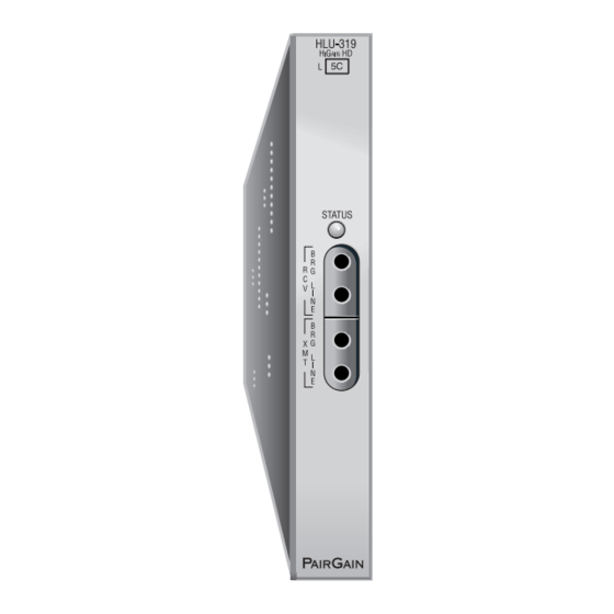
Front Panel 150-319-153-01, Revision 01 RONT ANEL The HLU-319 front panel is shown is Figure 1. The front panel components are described in Table 1 on page Figure 1. HLU-319 Front Panel April 30, 1999 HLU-319 List 5C... -
Page 11: Table 1. Front Panel Description
150-319-153-01, Revision 01 Front Panel Table 1. Front Panel Description Front Panel Feature Function Status LED Green Normal operation Flashing green HDSL loop acquisition Red Fuse Alarm Flashing red System alarm Yellow Self Test is in process or an HLU-319 Customer Remote Loopback (CREM) or a Network Local Loopback (NLOC) is in effect. -
Page 12: Installation
Upon receipt of the equipment, visually inspect it for signs of damage. If the equipment has been damaged in transit, immediately report the extent of damage to the transportation company and to PairGain Technologies, Inc. Figure 2. Installing the HLU-319 into a Shelf When installing an HLU in a chassis, be sure to wear an antistatic wrist strap. -
Page 13: Provisioning
150-319-153-01, Revision 01 Provisioning ROVISIONING AVIGATING THE AINTENANCE ERMINAL CREENS The following sections describe how the Maintenance Terminal displays an HLU-319 system with and without doublers, how to navigate through the maintenance screens, and how to select options. System Spans As shown in Figure 3, the HLU can support up to four doublers with five HDSL spans. -
Page 14: Selecting An Option
Provisioning 150-319-153-01, Revision 01 Selecting an Option To select an option within the Maintenance Terminal screens, you can: • Press the key indicated to the left of the selection. • Press the letter in parenthesis of the parameter to be changed. An invalid entry produces the following message and identifies the name of a field where the invalid entry occurred: >... -
Page 15: Table 3. Maintenance Terminal Screens
150-319-153-01, Revision 01 Provisioning Table 3. Maintenance Terminal Screens Screen Function See page: View Span Status Provides access to subscreens that allow you to monitor the HDSL line between the HLU and the HRU. Set Clock Allows you to set both the time and the date parameters at the HLU, and to update the same settings at the HRU. -
Page 16: View Span Status
Provisioning 150-319-153-01, Revision 01 TATUS The View Span Status option allows you to view six system status screens that provide information about the HDSL Loop 1, HDSL Loop 2, and the DS1. For doubler applications, the available Span Status screens depend on whether the system includes one, two, three, or four doublers. -
Page 17: Span Status Screen For Doubler Applications
150-319-153-01, Revision 01 Provisioning Span Status Screen for Doubler Applications If doublers have been added, status is also reported for these. After pressing to access the Maintenance Terminal Main Menu, press to navigate through the span status screens. Span Status can have up to six screens, depending on the number of HDUs. -
Page 18: Table 4. Span Status Fields And Descriptions
Provisioning 150-319-153-01, Revision 01 Table 4 lists the Span Status fields and descriptions. Table 5 on page 13 lists all possible alarms and their descriptions. Table 4. Span Status Fields and Descriptions Field Description Time Time of day when Span Status was checked. Date Date when Span Status was checked. -
Page 19: Table 5. Status Menu Messages: Alarms
150-319-153-01, Revision 01 Provisioning Table 5. Status Menu Messages: Alarms Message Full Name Description LLOS Local Loss of Signal No signal from HLU-319 local T1 input. RLOS Remote Loss of Signal No signal from HRU T1 input. LOSW1 Loss of Sync Word 1 or 2 One of the HDSL loops has lost synchronization. -
Page 20: Set Clock
Provisioning 150-319-153-01, Revision 01 LOCK Press from the Maintenance Terminal Main Menu to open the Set Clock screen (Figure SET CLOCK TIME: 00:14:33 DATE: 04/13/99 CIRCUIT ID#: Format: HH:MM MM/DD/YY NEW TIME: NEW DATE: (U)PDATE REMOTE? Figure 7. Set Clock Screen All time information is lost when power is removed. -
Page 21: System Settings
150-319-153-01, Revision 01 Provisioning All time information is lost when power is removed. The last date, however, is retained in NVRAM and reappears when power is restored. YSTEM ETTINGS & Press from the Maintenance Terminal Main Menu to open the System Settings screen (Figure SYSTEM SETTINGS TIME: 12:46:06... -
Page 22: Table 6. Hlu-319 System Settings Screen Options
Provisioning 150-319-153-01, Revision 01 Table 6 describes the System Settings screen options. Factory default settings are shown in bold. Table 6. HLU-319 System Settings Screen Options System Settings Selection Description Equalization Sets the Equalizer to DSX-1 for 0 to 133 feet. Sets the Equalizer to DSX-1 for 133 to 266 feet. - Page 23 150-319-153-01, Revision 01 Provisioning Table 6. HLU-319 System Settings Screen Options (Cont.) System Settings Selection Description Framing AUTO Configures the HiGain system to operate in an auto-framing (AUTO) mode in which it continuously searches the input T1 bit stream for a valid SF or ESF frame pattern. This feature is required for fractional T1 applications (DS0 blocking) where it insures proper channel time slot alignment.
-
Page 24: Bpv And Ber Options
Provisioning 150-319-153-01, Revision 01 BPV and BER Options The HLU-319 improves HiGain’s compatibility with DLC feeder applications because of its ability to transmit T1 BPV occurrences between its T1 interfaces. This feature is required to support protection switching in DLC applications. -
Page 25: Ds0 Blocking Option
150-319-153-01, Revision 01 Provisioning DS0 Blocking Option To set the DS0 Blocking option from the Main screen: Press & to select the Systems Settings screen (see Figure 8 on page 15). Press for the DS0 blocking selection. The DS0 channels are blocked or unblocked by entering each channel number. -
Page 26: Hais Selections
Provisioning 150-319-153-01, Revision 01 HAIS Selections The HAIS option provides two selections for the T1 transmit outputs at both the HLU-319 and HRU for HDSL loss of sync conditions. • 1LP causes the AIS (LOS if ALMP is set to LOS) pattern to be transmitted at both T1 outputs when either of the two HDSL loops experience an out-of-sync (LOSW) condition or when a margin alarm occurs. -
Page 27: Ground Fault Detect
150-319-153-01, Revision 01 Provisioning Ground Fault Detect The HLU-319 has a Ground Fault Detect (GFD) circuit which detects a ground or a resistive path to ground on any wire of any loop of any span with a non-zero voltage. For low (135 V) applications, such a circuit is active during start-up by applying the bipolar voltage to the loops. -
Page 28: Loopback Menu For Doubler Applications
Provisioning 150-319-153-01, Revision 01 Loopback Menu for Doubler Applications LOOPBACK MENU TIME: 00:03:33 DATE: 04/13/99 CIRCUIT ID#: A. DISABLE LOOPBACKS B. NETWORK LOOP HLU (NLOC) M. NETWORK LOOP DOUBLER 4 (NDU4) C. NETWORK LOOP HRU (NREM) N. CUSTOMER LOOP DOUBLER 4 (CDU4) D. -
Page 29: Initiating A Loopback
150-319-153-01, Revision 01 Provisioning Initiating a Loopback To send one of the available loopbacks, press the appropriate letter in the Loopback Menu. The following prompt appears: PLEASE WAIT....A series of dots moves from left to right indicating that the command has been issued. When this process completes, the system returns to the Maintenance Terminal Main Menu. -
Page 30: Performance Data Screens
Provisioning 150-319-153-01, Revision 01 ERFORMANCE CREENS The Performance Data screens show the Errored Seconds (ES) and Unavailable Seconds (UAS) for both HDSL loops and each T1 input at 15-minute intervals over a 4-hour time interval. Earlier and later data, in 4-hour time periods on different span screens, can be accessed by pressing (Previous) or (Next) respectively. -
Page 31: Performance Data Screen For Non-Doubler Applications
150-319-153-01, Revision 01 Provisioning Performance Data Screen for Non-doubler Applications Date: 04/13/99 PERFORMANCE DATA CIRCUIT ID#: ERRORED SECONDS/UNAVAILABLE SECONDS HDSL-1 HDSL-2 20:30 20:45 21:00 21:15 21:30 21:45 22:00 22:15 22:30 22:45 23:00 23:15 23:30 23:45 00:00 00:15 (E)xit (P)revious (N)ext Figure 12. -
Page 32: View Performance History
Provisioning 150-319-153-01, Revision 01 ERFORMANCE ISTORY The Performance History screen shows the daily occurrences of ES and UAS over a 31-day period. Errored Seconds and Unavailable Seconds for both HDSL loops and each of the two DS1 inputs are listed for the current and previous period. -
Page 33: Performance History For Doubler Applications
150-319-153-01, Revision 01 Provisioning Performance History for Doubler Applications The Performance History screen displays information by span when doublers are used. With multiple doublers (up to four), there can be as many as five span screens. Figure 15 lists data for the fifth span (Doubler #4 to the HRU). Time: 00:26:29 SPAN 5 PERFORMANCE HISTORY—31 DAY CIRCUIT ID#:... -
Page 34: View Alarm History Screens
Provisioning 150-319-153-01, Revision 01 LARM ISTORY CREENS The View Alarm History screen allows you to view alarms that are currently active. The following explains some features of the View Alarm History screen: • First and Last columns contain the time and date stamp of the first and last occurrence of each alarm. •... -
Page 35: Alarm History Screen For Non-Doubler Applications
150-319-153-01, Revision 01 Provisioning Alarm History Screen for Non-doubler Applications Press from the Maintenance Terminal Main Menu to view the Alarm History screen for an application without a doubler (Figure 16). ALARM HISTORY TIME: 00:17:18 DATE: 04/13/99 CIRCUIT ID#: Type First Last Current... -
Page 36: Alarm History Screen For Doubler Applications
Provisioning 150-319-153-01, Revision 01 Alarm History Screen for Doubler Applications The Alarm History screen displays information by span. With no doubler, there is only one span (Figure 16). With multiple doublers (up to four), there can be as many as five span screens. Press from the Maintenance Terminal Main Menu to view the Alarm History screen. -
Page 37: System Inventory Screen
150-319-153-01, Revision 01 Provisioning YSTEM NVENTORY CREEN The System Inventory screen lists the six possible units that can comprise one HiGain circuit: one HLU, one HRU and up to four doublers. The information in the System Inventory Screen is presented as follows: •... -
Page 38: Troubleshooting
Troubleshooting 150-319-153-01, Revision 01 ROUBLESHOOTING YSTEM LARMS Table 9 lists possible HLU-319 alarm states. More than one alarm condition can exist at any given time, but only one message can be displayed. For multiple alarms, only the highest priority alarm displays. Table 9. -
Page 39: Loopback Operation
150-319-153-01, Revision 01 Troubleshooting OOPBACK PERATION HiGain has a family of loopback options. The most important of these is the SmartJack (SMJK) loopback, which enables an HRU response to the standard (2/3-in-5) SMJK in-band loopback codes in emulation of standard Network Interface Device (NID) functions. -
Page 40: Loopback Test Procedures
Troubleshooting 150-319-153-01, Revision 01 A5LB differs from A2LB in that A5LB does not block the arming code from exiting the HLU-319 into the network. A2LB can be configured to either block this arming code after two seconds, and replace it with the AIS code, or to unblock it by executing the FAR-END ACTIVATE code. -
Page 41: Loopback Operation
150-319-153-01, Revision 01 Troubleshooting Loopback Operation The complete family of loopbacks that a HiGain system equipped with the HDU-409 can execute is shown in Figure 19. Eight of those loopbacks, NDU1, NDU2, NDU3, NDU4; CDU1, CDU2, CDU3, CDU4 occur in the doubler. -
Page 42: Gnlb Loopback Test Procedures
Troubleshooting 150-319-153-01, Revision 01 The more common generic, SPLB in-band loopback commands for doubler loopbacks are listed in Table 10. The commands are very specific combinations of either 6 or 7 bits that continuously repeat. All NXXX loopbacks are towards the network. All CXXX loopbacks are towards the customer. Table 10. - Page 43 150-319-153-01, Revision 01 Troubleshooting Notes on Doubler GNLB Loopback Test Procedures: • Doubler #1 can engage loopback from the remote location (CDU1) by issuing the (4-in-6) loopback command at the HRU DS1 input port. • Doubler #1 can engage loopback from the local location (NDU1) by issuing the (2-in-6) loopback command at the HLU-319 DS1 input port.
- Page 44 HLU-319 may indicate one more or one less bit error, depending on the test set type and the number of frame bits contained in the block of errored bits. To avoid this uncertainty, PairGain recommends sending the IR commands unframed.
-
Page 45: Table 11. Addressable 1, 2, 5 (A1Lb, A2Lb, A5Lb) Repeater Loopback Commands
150-319-153-01, Revision 01 Troubleshooting Information specific to HiGain doublers is shown in bold in Table Table 11. Addressable 1, 2, 5 (A1LB, A2LB, A5LB) Repeater Loopback Commands Name Description Code ARMING or NI LPBK (in-band) Arming code 11000 11000 … ARMING or NI LPBK (ESF Data Link) Arming code 1111(F) - Page 46 Troubleshooting 150-319-153-01, Revision 01 A3LB and A4LB Test Procedures The HLU-319 can be looped back by sending the Addressable Office Repeater (AOR) LPBK activation code 1111(F) 1111(F) 0001(1) 1110(E) for at least 5 seconds. This causes the HLU-319 to enter the NLOC state. The Loopback Time-out option can be set by the user to: •...
-
Page 47: Table 12. Addressable 3 And 4 (A3Lb And A4Lb) Repeater Loopback Commands
150-319-153-01, Revision 01 Troubleshooting Information specific to HiGain doublers is shown in bold in Table Table 12. Addressable 3 and 4 (A3LB and A4LB) Repeater Loopback Commands Position Name Code HLU-319 LU FROM NI NLOC 1111(F) 1111(F)0001(1)1110(E) HLU-319 LU from CI CREM 0011(3)1111(F)0001(1)1110(E) HDU DOUBLER 1 FROM NI... -
Page 48: Appendix A - Specifications
Appendix A - Specifications 150-319-153-01, Revision 01 A - S PPENDIX PECIFICATIONS HDSL Line Code 784 kbps 2B1Q +13.5 dBm ±0.5 dB at 135 Ω Output 135 Ω Line Impedance Span Voltage -135 V to ± 220 Vdc Start-up Time (per span) 30 sec. -
Page 49: Hdsl Insertion Loss Guidelines
150-319-153-01, Revision 01 Appendix A - Specifications HDSL I NSERTION UIDELINES Each loop has no more than 35 dB of loss at 196 kHz, with driving and terminating impedances of 135 Ω. provides a “loss” guide for the various cable gauges at 196 kHz and 135 Ω. The table applies to the Table 13 HDSL cable pairs between the HLU, HRU, and HDU modules. -
Page 50: Power Consumption With Doublers
Appendix A - Specifications 150-319-153-01, Revision 01 Power Consumption with Doublers Table 15 through Table 21 list the power consumed and dissipated by the HLU-319 when it is used with any of the four basic doubler types in the HiGain family. The maximum current drawn by the CO supply is also listed. Table 15 covers single doubler, line-powered circuits on 9 kft, 26 AWG loops. -
Page 51: Table 17. Power Parameters: Single Doubler With Hdu-409 List 2
150-319-153-01, Revision 01 Appendix A - Specifications Table 17 covers single doubler, line-powered circuits on 9 kft, 26 AWG loops. Table 17. Power Parameters: Single Doubler with HDU-409 List 2 42.5 V Power HRU CPE Heat Dissipation 42.5 V Current Consumption HRU Model No. -
Page 52: Table 20. Power Parameters: Two Doublers With Hdu-409 List 2
Appendix A - Specifications 150-319-153-01, Revision 01 Table 20 applies to two doubler, line-powered circuits on 9 kft, 26 AWG Loops. Table 20. Power Parameters: Two Doublers with HDU-409 List 2 42.5 V Power HRU CPE Heat Dissipation 42.5 V Current Consumption HRU Model No. -
Page 53: Maximum Power Dissipation
150-319-153-01, Revision 01 Appendix A - Specifications AXIMUM OWER ISSIPATION The Maximum Power Dissipation measures the power that is converted into heat that builds up within the unit. It contributes to the total heat generated in the space around the unit. It is used to determine the maximum number of fully loaded shelves per bay that does not exceed the maximum allowable power dissipation density in watts per square foot to comply with GR-63. -
Page 54: Hlu-319 Card Connector
Network Management Control Bus The HLU-319 provides a Network Management Control Bus on pin 7 of the card-edge connector. This allows the various PairGain Management System protocols to manage the HLU through the HMU-319 HiGain Management Unit. Some HLU-319 features are affected when it is under management. Consult the management unit practice for further information. -
Page 55: System Alarm Output Pin
150-319-153-01, Revision 01 Appendix A - Specifications System Alarm Output Pin Pin H on the card-edge connector (see Figure 20) is the HLU-319 System Alarm output pin. The following notes apply to Pin H: • Pin H replaces the Local Loss of Signal (LLOS) on normal high-density (3192) repeaters. •... -
Page 56: Appendix B - Functional Operation
UNCTIONAL ESCRIPTION PairGain HDSL technology provides full-duplex services at standard T1 rates over copper wires between an HLU and an HRU, that comprises one HiGain system. HiGain systems use PairGain 2-Binary 1-Quartenary (2B1Q) HDSL transceiver systems to establish two, full-duplex, 784 kbps data channels between the HLU-319 and a remotely located HDU or HRU. -
Page 57: Appendixc - Compatibility
The HLU-319 is compatible with the following T1 repeater shelves and associated equipment: • PairGain HMS-317(28-slot, 23-inch shelf) • PairGain HHS-319 (3-slot, 19-inch horizontal shelf) • PairGain HMS-308 (8-slot, 3192 mechanics, remote enclosure) • Charles Ind. #3192 (28-slot connectorized) • Charles Ind. #3192-9F Alarm Card •... -
Page 58: Table 22. Higain Doubler Deployment Matrix
Appendix C - Compatibility 150-319-153-01, Revision 01 All generations of HiGain HLU and HRU modules are compatible with each other. Although all HiGain doublers are backward-compatible with all prior HLU and HRU models, some of the circuit application enhancements of newer doubler models require that all circuit modules be of the same vintage in order to realize these enhancements. -
Page 59: Appendixd - Product Support
OCUMENTATION The complete HLU-319 List 5C techncial practice can be download from the PairGain Technical Publications Web page at: www.pairgain.com. A password is required. If you do not have a password, contact your PairGain sales representative. If you have any comments on any PairGain documentation, send email to technical_publications@pairgain.com. -
Page 60: Returns
Locate the number of the purchase order under which the equipment was purchased. You will need to provide this number to PairGain Customer Service to obtain a return authorization. Call or write PairGain Customer Service to ask for a Return Material Authorization (RMA) number and any additional instructions. Use the telephone or fax number listed below: •... -
Page 61: Appendix E - Glossary
150-319-153-01, Revision 01 Appendix E - Glossary E - G PPENDIX LOSSARY 2 Binary,1 Quaternary High Capacity Digital Service 2B1Q HCDS Alarm Cut Off High-bit-rate Digital Subscriber Line HDSL Alarm Indicator Signal HiGain Doubler Unit Alarm Pattern HiGain Line Unit ALMP Alternate Mark Inversion HiGain Management Shelf... - Page 62 Appendix E - Glossary 150-319-153-01, Revision 01 Signal-to-Noise Ratio Special Loopback SPLB Total Error Count Total System Error Count TSEC Unavailable Seconds Transmit April 30, 1999 HLU-319 List 5C...
-
Page 63: Certification And Warranty
Do not try to repair the unit. If it fails, replace it with another unit and return the faulty unit to PairGain for repair. Any modifications of the unit by anyone other than an authorized PairGain representative voids the warranty. - Page 64 Corporate Office 14402 Franklin Avenue Tustin, CA 92780 Tel: (714) 832-9922 Fax: (714) 832-9924 For Technical Assistance: (800) 638-0031...
Need help?
Do you have a question about the HiGain HLU-319 and is the answer not in the manual?
Questions and answers