
Subscribe to Our Youtube Channel
Related Manuals for PairGain HiGain HRU-402


Summary of Contents for PairGain HiGain HRU-402
- Page 1 EMOTE Model List Number Part Number HRU-402 150-1592-02 ECHNOLOGIES NGINEERING ERVICES ECHNICAL RACTICE ™150-402-102-01S¨ 150-402-102-01 ECTION...
- Page 2 ©Copyright 1998 PairGain Technologies, Inc. PairGain and HiGain are registered trademarks of PairGain Technologies, Inc. Information contained in this document is company private to PairGain Technologies, Inc., and shall not be modified, used, copied, reproduced or disclosed in whole or in part without the written consent of PairGain.
- Page 3 150-402-102-01, Revision 01 Using This Manual SING ANUAL Two types of messages, identified by icons, appear in the text. Notes contain information about special circumstances. Cautions indicate the possibility of equipment damage or the possibility of personal injury. HRU-402 List 2 July 27, 1998...
- Page 4 Using This Manual 150-402-102-01, Revision 01 July 27, 1998 HRU-402 List 2...
-
Page 5: Table Of Contents
150-402-102-01, Revision 01 Table of Contents ABLE OF ONTENTS Product Overview________________________________________ 1 Features ..................2 Applications ................3 Product Description ..............5 Front Panel..............5 Rear Panel..............8 Installation ____________________________________________ 10 Inspecting Your Shipment ............. 10 Installing the HRU-402 List 2..........10 Installation Test.............. - Page 6 Table of Contents 150-402-102-01, Revision 01 Appendix A: Additional Technical Information_______________42 Specifications .................42 Card-edge Pinout Diagram .............44 Features ..................45 Bipolar Violation Transparency (BPVT) and Bit Error Rate (BER) Options ..........45 Remote DS1 Alarm (RDA) Option......46 Alarm Pattern Option (ALMP) Option ....47 DS1 Line Code Auto Option........47 Functional Description ............48 Operational Capabilities...........48...
- Page 7 150-402-102-01, Revision 01 List of Figures IST OF IGURES Figure 1. Typical HiGain System............1 Figure 2. Front Panel................5 Figure 3. Backplane User Option Locations .......... 8 Figure 4. HRU-402 Installed in a Remote Enclosure......11 Figure 5. DB-9 and DB-25 RS-232 I/O Interfaces....... 16 Figure 6.
- Page 8 List of Tables 150-402-102-01, Revision 01 IST OF ABLES Table 1. HDSL Loss Over Cables ............3 Table 2. Front Panel Components ............6 Table 3. Rear Panel Components............9 Table 4. HLU-231 List 8 Four-Character Front Panel Messages ..13 Table 5. Maintenance Terminal Navigational Keys ......21 Table 6.
-
Page 9: Product Overview
RODUCT VERVIEW ® ® This technical practice describes the PairGain HiGain Remote Unit, Model HRU-402 List 2, and its use with and without doubler and line units. This remote unit functions as the remote end of a repeaterless T1 transmission system. -
Page 10: Features
Lightning and power cross protection on HDSL and DS1 interfaces • 784 kbps full-duplex 2B1Q HDSL Transmission on two pairs • DS0 blocking • Compatible with PairGain 1 x 1 Protection Switching System • Narrow SLIM mechanics (half-width 400 mechanics) • Lower Power Consumption •... -
Page 11: Applications
150-402-102-01, Revision 01 Product Overview PPLICATIONS The HiGain system provides a cost-effective and easy-to-deploy method for delivering T1 service over a single metallic pair. Conventional in-line T1 repeaters, cable pair conditioning, pair separation, and bridged tap removal are not required. Each cable pair loop has less than 35 decibel (dB) of loss at 196 kHz with 135Ω... - Page 12 Product Overview 150-402-102-01, Revision 01 also be used with the following line and doubler units for four and five span applications: • HLU-231 List 8x • HLU-319 List 5x • HLU-388 List 8x • HDU-409, HDU-407 or HDU-404 July 27, 1998 HRU-402 List 2...
-
Page 13: Product Description
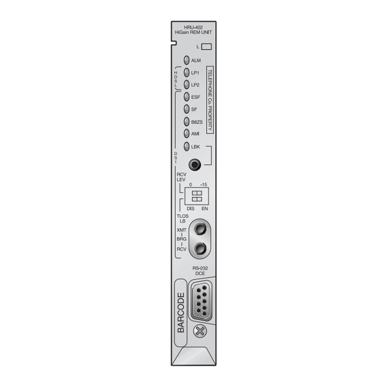
150-402-102-01, Revision 01 Product Overview RODUCT ESCRIPTION Front Panel Figure 2 Table 2 identify the remote unit front panel components. Table 2 also describes the functions of the front panel components. Figure 2. Front Panel HRU-402 List 2 July 27, 1998... -
Page 14: Table 2. Front Panel Components
Product Overview 150-402-102-01, Revision 01 Table 2. Front Panel Components Name Function DS1 XMT and RCV Provides bridging test and monitor access jacks to the CPE DS1 Bridging Jacks interface. Provides both monitor and test access capability. Figure 25 for circuit details. Alarm (ALM) LED Shows alarm states for Remote and Local Loss of Signal (LOS) Solid Red Indicates a LOS condition at HRU T1 input. - Page 15 150-402-102-01, Revision 01 Product Overview Table 2. Front Panel Components (Continued) Name Function Craft Port (RS-232 Provides bidirectional communication between the unit and an DB-9 Connector) external maintenance terminal through an RS-232 interface to allow configuration and performance monitoring through the Maintenance Terminal menus.
-
Page 16: Rear Panel
Product Overview 150-402-102-01, Revision 01 Rear Panel The HRU-402 List 2 has four user options that must be set before you install the unit into a shelf or enclosure. Two of these options, DS1 Receive Level and TLOS, are located on the front panel. The other two, Sealing Current (SCURR) and Local Power (LPWR), are located at the back of the printed circuit board adjacent to the card-edge connector as shown in Figure... -
Page 17: Table 3. Rear Panel Components
150-402-102-01, Revision 01 Product Overview Table 3. Rear Panel Components Name Function Sealing Current- Rear Unit Switch S1 Prevents the flow of simplex sealing current over the HDSL pairs towards the upstream unit. Allows the flow of simplex sealing current over the HDSL pair towards the upstream unit. -
Page 18: Installation
Your shipment should consist of: • One HRU-402 List 2 • PairGain Technologies HiGain Remote Unit 402 List 2 technical practice HRU-402 L NSTALLING THE The HRU-402 List 2 mounts in the following shelves (indoor use): •... -
Page 19: Figure 4. Hru-402 Installed In A Remote Enclosure
150-402-102-01, Revision 01 Installation Set the user options as described in “Rear Panel” on page Slide the remote unit into the card guides for the desired slot, then push the unit into the enclosure until it is seated in the card-edge connector. Figure 4. -
Page 20: Installation Test
Installation 150-402-102-01, Revision 01 NSTALLATION Testing of your HiGain system allows you to verify the integrity of the HDSL channels to the HLU as well as the DS1 channels to the customer and the HLU DSX-1 interface. While the HRU-402 List 2 displays system condition messages at the Remote and Maintenance Terminals, and by color-coded LED displays on the front panel, the HLU displays system conditions by four-character LCD messages. -
Page 21: Front Panel Messages
150-402-102-01, Revision 01 Installation When the HRU is looped back towards the CPE or CLOC, the LBK LED blinks yellow at 1 time per second. When HiGain is in special loopback ARMED state, the LBK LED blinks yellow at four times a second. RONT ANEL ESSAGES... - Page 22 Installation 150-402-102-01, Revision 01 Table 4. HLU-231 List 8 Four-Character Front Panel Messages (Continued) Message Name Description S3L1 or 2 Signal 3 Loop 1 The 2nd Doubler and either HRU or 3rd Doubler or Loop 2 transceivers are trying to establish contact with each other on loops 1 or 2 of span 3.
-
Page 23: Connecting To A Terminal Emulator
150-402-102-01, Revision 01 Installation Table 4. HLU-231 List 8 Four-Character Front Panel Messages (Continued) Message Name Description Power Feed Off HDSL span power has been turned off by setting the PWFD FEED OFF option to DIS. Power Feed One of the HDSL loops has been grounded. FEED GRD Ground BAD RT? -
Page 24: Figure 5. Db-9 And Db-25 Rs-232 I/O Interfaces
Installation 150-402-102-01, Revision 01 HRU-402 List 2, DB-9, and two types (DB-9 and DB-25) of RS-232 I/O interfaces on the HLUs. Maintenance Terminal DB-9 Connector (DTE) HRU-402 DB-9 Connector (DCE) RD (Receive Data) TD (Transmit Data) Maintenance Terminal DB-25 Connector (DTE) Figure 5. -
Page 25: Figure 6. Connecting The Hru-402 To A Maintenance Terminal
150-402-102-01, Revision 01 Installation Figure 6. Connecting the HRU-402 to a Maintenance Terminal Configure the maintenance terminal to the following communication settings: • 1200 to 9600 baud (9600 baud is recommended) • Parity: None • 8 data bits • 1 stop bit •... -
Page 26: Using The Maintenance Terminal
(Figure 7 shows the main menu of a local session). The main menu heading HiGain HRU-402 Maintenance Terminal Main Menu identifies the screen as a Local Login session. However, after the remote unit and HLU establish synchronization, the port interface will reset to a remote session. -
Page 27: Figure 7. Local Login Main Menu Screen
150-402-102-01, Revision 01 Using the Maintenance Terminal This screen can be identified by the heading, HiGain HLU-231 Remote Terminal Main Menu. This is the remote unit you will be connected to. At this point, you may choose to terminate the remote session by pressing under the remote logoff option (Figure 10). -
Page 28: Navigating The Hru Maintenance Menus
150-402-102-01, Revision 01 +++++++++++++++++++++++++++++++++++++++++++++++++++++++ RRRRR EEEEEE TTTTTTT EEEEEEE RRRRR EEEEEE EEEEEE EEEEEE EEEEEEE PAIRGAIN TECHNOLOGIES +++++++++++++++++++++++++++++++++++++++++++++++++++++++ HIT <ENTER> TO LOG IN Figure 8. Remote Login Main Menu Screen HRU M AVIGATING THE AINTENANCE ENUS System Spans There are five to seven view-only screens available for viewing system performance, status and history, depending on the number of spans in a particular application. -
Page 29: Navigation Keys
150-402-102-01, Revision 01 Using the Maintenance Terminal Navigation Keys Table 5 describes keys you can use on the maintenance terminal keyboard to navigate within the HRU-402 List 2 Maintenance menus. Table 5. Maintenance Terminal Navigational Keys Function Logs into the Remote Terminal menus Exits the current menu Updates a report Selects the next Span Status screen... -
Page 30: Hru Maintenance Terminal Main Menu
Using the Maintenance Terminal 150-402-102-01, Revision 01 HRU M AINTENANCE ERMINAL Table 6 describes the function of each menu selection. Table 6. Maintenance and Remote Terminal Menus Menu Function View Span Provides access to a submenu that allows you “View Span Status” on Status to monitor the HDSL line between the HLU and page 23... -
Page 31: View Span Status
150-402-102-01, Revision 01 Using the Maintenance Terminal HI-GAIN HLU-231 REMOTE TERMINAL MAIN MENU (ver V6.x-8) CIRCUIT ID#: A. VIEW SPAN STATUS C. SYSTEM SETTINGS D. LOOPBACK MODE: NONE E. VIEW PERFORMANCE DATA F. VIEW PERFORMANCE HISTORY G. VIEW ALARM HISTORY H. -
Page 32: Figure 11. View Span Status Screen For Non-Doubler Applications
Using the Maintenance Terminal 150-402-102-01, Revision 01 When no doublers are in use, the following Span Status screen displays: TIME: 00:14:11 SPAN STATUS DATE: 02/02/98 Circuit ID#: ALARMS: NONE LOOPBACK: OFF POWER LEVEL: LOW HDSL-1 HDSL-2 HDSL-1 HDSL-2 cur/min/max cur/min/max cur/min/max cur/min/max MARGIN: 21/17/21 20/17/21... -
Page 33: Figure 12. Span 5 Status Screen For Four Doubler Applications
150-402-102-01, Revision 01 Using the Maintenance Terminal When doublers are in use, the following Span Status screen displays: TIME: 00:14:11 SPAN 5 STATUS DATE: 02/02/98 Circuit ID#: ALARMS: NONE LOOPBACK: OFF POWER LEVEL: HIGH HDU4 HDSL-1 HDSL-2 HDSL-1 HDSL-2 cur/min/max cur/min/max cur/min/max cur/min/max MARGIN: 21/21/21 21/21/21... -
Page 34: Table 7. Span Status Fields And Descriptions
Using the Maintenance Terminal 150-402-102-01, Revision 01 Table 7. Span Status Fields and Descriptions Field Description Time Time of day when Span Status was checked. Date Date when Span Status was checked. Alarms Presence or absence of alarm conditions. See Table Loopback Indicates Off condition or identifies specific active loopback. -
Page 35: Set Clock
150-402-102-01, Revision 01 Using the Maintenance Terminal Set Clock This option is available during Local Login only (see Figure From the Local Login screen, press to display the Set Clock screen. SET CLOCK TIME: 00:14:33 DATE: 02/02/98 CIRCUIT ID#: Format: HH:MM MM/DD/YY NEW TIME: NEW DATE:... -
Page 36: System Settings
Using the Maintenance Terminal 150-402-102-01, Revision 01 System Settings The System Settings screen allows you to analyze and view configurable parameters set at the HLU. These screens are for viewing only and cannot be altered. The system settings can only be set at the HLU. Type from either the Maintenance Terminal Main Menu or the Remote Terminal Main menu to view the System Settings screen:... -
Page 37: Table 8. System Settings Fields And Descriptions
150-402-102-01, Revision 01 Using the Maintenance Terminal Table 8. System Settings Fields and Descriptions Field Description Time Time of day when System Settings were checked. Date Date when System Settings were checked. Equalization Indicates settings for equalizer of either EX1, 0 (DSX-1 for 0-133 ft), 133 (DSX-1 for 133-266 ft), 266 (DSX-1 for 266-399 ft), 399 (DSX-1 399-533 ft), 533 DSX-1 for 533-655 ft). -
Page 38: Loopback Menu
Using the Maintenance Terminal 150-402-102-01, Revision 01 Table 8. System Settings Fields and Descriptions (Continued) Field Description DS0 Blocking Indicates status of DS0 blocked channels and identifies the channels that have been blocked (using “xx” symbols underneath each blocked channel). A None setting indicates no channels are blocked. A BLK setting indicates some channels are blocked. -
Page 39: Figure 15. Loopback Screen Without Doublers
150-402-102-01, Revision 01 Using the Maintenance Terminal From the Remote Terminal Main Menu, type to display the Loopback Menu. When no doublers are in use, the following screen displays: LOOPBACK MENU TIME: 00:15:34 DATE: 02/02/98 CIRCUIT ID#: A. DISABLE LOOPBACKS B. -
Page 40: Figure 16. Loopback Screen With Four Doublers
Using the Maintenance Terminal 150-402-102-01, Revision 01 When doublers are in use, the following Loopback screen displays: LOOPBACK MENU TIME: 00:03:33 DATE: 02/02/98 CIRCUIT ID#: A. DISABLE LOOPBACKS B. NETWORK LOOP HLU (NLOC) M. NETWORK LOOP DOUBLER 4 (NDU4) C. NETWORK LOOP HRU (NREM) N. -
Page 41: View Performance Data
150-402-102-01, Revision 01 Using the Maintenance Terminal Table 9. Loopback Field Messages and Descriptions Messages Full Name Description NREM Network Remote Loopback at HRU (remote) towards network. Loopback NLOC Network Local Loopback Loopback at HLU (local) towards network. CLOC Customer Local Loopback at HRU (local) towards CI. -
Page 42: Figure 17. Performance Data Screen
Using the Maintenance Terminal 150-402-102-01, Revision 01 applications, the available View Performance Data screens displayed are dependent upon the configuration (one doubler or two doublers). From the Remote Terminal Main Menu, type to display the Performance Data screen. You can also access this screen through the Maintenance Terminal Main Menu by typing . -
Page 43: Figure 18. Span 5 Performance Data Screen
150-402-102-01, Revision 01 Using the Maintenance Terminal When doublers are in use, the following Span Status screen displays: Date: 02/02/98 SPAN 5 PERFORMANCE DATA CIRCUIT ID#: ERRORED SECONDS/UNAVAILABLE SECONDS HDSL-1 HDSL-2 HDU1 HDU2 HDU1 HDU2 08:00 000/000 000/000 000/000 000/000 000/000 000/000 08:15... -
Page 44: View 7 Day History
Using the Maintenance Terminal 150-402-102-01, Revision 01 View 7 Day History The View 7 Day History screen shows the number of ES/UAS occurrences in 24 hour increments for a seven day period. The presentation format is: ES/UAS for the HLU and the HRU-402 List 2 for the DS1 signal, HDSL Loop 1 and HDSL Loop 2 (for non-doubler applications). -
Page 45: Figure 20. Span 5 Performance Data Screen
150-402-102-01, Revision 01 Using the Maintenance Terminal When doublers are in use, the following Performance Data screen is displayed: Time: 00:16:55 7 DAY HISTORY CIRCUIT ID#: SPAN 5 ERRORED SECONDS/UNAVAILABLE SECONDS HDSL-1 HDSL-2 HDU4 HDU4 01/26 00000/00000 00000/00000 00000/00000 00000/00000 00000/00000 00000/00000 01/27 00000/00000 00000/00000 00000/00000 00000/00000 00000/00000 00000/00000 01/28... -
Page 46: View Alarm History
Using the Maintenance Terminal 150-402-102-01, Revision 01 View Alarm History The View Alarm History screen allows you to view both active and retired alarms. To view the Alarm History screens: From the Remote Terminal Main Menu, type to display the Alarm History screen for non-doubler applications. -
Page 47: Table 10. Alarm History Fields And Descriptions
150-402-102-01, Revision 01 Using the Maintenance Terminal Table 10. Alarm History Fields and Descriptions Field Description Type Identifies the type of alarm LOS, DS1-HLU First and last instance of LOS at the HLU; Current condition, number of alarms LOS, DS1-HRU First and last instance of LOS at the HRU;... -
Page 48: View System Inventory
Using the Maintenance Terminal 150-402-102-01, Revision 01 For doubler applications, the following screen displays: ALARM HISTORY TIME: 00:17:18 DATE: 02/02/98 CIRCUIT ID#: HLU Type First Last Current Count LOS, DS1-HLU LOS, DS1-HRU SPAN5 LOSW, HDSL1 SPAN5 LOSW, HDSL2 SPAN5 MARGIN L1 02/02/98-03:48 02/02/98-03:48 SPAN5 MARGIN L2... -
Page 49: Figure 23. Inventory Screen
150-402-102-01, Revision 01 Using the Maintenance Terminal The IDs can only be set at the HLU. They are limited to 24 alphanumeric characters and, like the system settings, are stored in Non-volatile Random Access Memory (NVRAM), meaning the data remains even when power is lost or turned off. -
Page 50: Appendix A: Additional Technical Information
Appendix A: Additional Technical Information 150-402-102-01, Revision 01 A: A PPENDIX DDITIONAL ECHNICAL NFORMATION Appendix A contains additional information about the HRU-402 List 2. PECIFICATIONS Physical Material Steel Finish Zinc plated Mounting Any standard 400 or SLIM (one-half 400) Dimensions Height 5.6 in. - Page 51 150-402-102-01, Revision 01 Appendix A: Additional Technical Information Environment Operating -40° to 149°F (-40° to + 65°C) temperature Operating humidity 5 to 95% non-condensing HDSL Line code 784 kbps 2B1Q full duplex Output +13 dB ± 0.5 dB @ 135Ω Line impedance 135Ω...
-
Page 52: Card-Edge Pinout Diagram
Appendix A: Additional Technical Information 150-402-102-01, Revision 01 EDGE INOUT IAGRAM The HRU-402 List 2 occupies one slot in a remote enclosure. The card-edge pinout diagram for the remote unit is shown in Figure Figure 24. Card-edge Pinouts July 27, 1998 HRU-402 List 2... -
Page 53: Features
150-402-102-01, Revision 01 Appendix A: Additional Technical Information EATURES The following describes additional information on some of the features included with the HRU-402 List 2. Bipolar Violation Transparency (BPVT) and Bit Error Rate (BER) Options The HRU-402 List 2 and its associated line units improve compatibility with Data Link Control (DLC) feeder applications due to T1 BPVT transmit capability between T1 interfaces. -
Page 54: Remote Ds1 Alarm (Rda) Option
Appendix A: Additional Technical Information 150-402-102-01, Revision 01 The BER option also uses this (BPVT/CRC) TEC to generate an alarm if enabled. The HLU combines the one second TEC counts in both directions for the last 60 seconds. The line unit uses this one minute Total System Error Count (TSEC) to generate an alarm if it exceeds the selected BER threshold of (1E-6 or 1E-7) as follows: •... -
Page 55: Alarm Pattern Option (Almp) Option
150-402-102-01, Revision 01 Appendix A: Additional Technical Information Alarm Pattern Option (ALMP) Option To further improve HiGain’s compatability with the switch-to-protect features used in DLC feeder applications, the line unit has an ALMP which allows the user to select either AIS or LOS T1 output payloads for the following alarms: •... -
Page 56: Functional Description
This section describes the functions of the HRU-402 List 2. Operational Capabilities HiGain utilizes PairGain’s 2B1Q HDSL transceiver system to establish two full-duplex 784 kbps data channels between the HLU and a remotely mounted HRU-402 List 2. This system provides a total capacity of 1.568 Mbps between the two units. -
Page 57: Local And Line Powering
150-402-102-01, Revision 01 Appendix A: Additional Technical Information Figure 25. HRU-402 List 2 Block Diagram Local and Line Powering The HRU-402 List 2 can be line or local powered. The remote unit always chooses the local -48 Vdc power source from the power supply attached to pair 35(-) and 17(+) of the card-edge connector (Figure 24 on page 44). -
Page 58: Simplex Sealing Current Information
Appendix A: Additional Technical Information 150-402-102-01, Revision 01 The following line units automatically turn off their line power supply when they are connected to a locally powered HRU-402 List 2: • List 6 and higher versions of the HLU-231 • All versions of the HLU-319 and HLU-388 Refer to the appropriate HLU technical practice if you need more information about its local and line powering capabilities. -
Page 59: Loopback Design Description
150-402-102-01, Revision 01 Appendix A: Additional Technical Information The simplex sealing current flow is blocked if it is used with HDU-451 List 1, 2, 3 or 3B doublers. These doublers are only compatible with the metallic sealing current of earlier remote units. To provide a path through which the simplexed sealing current can flow, the following doublers must be used with the HRU-402 List 2: •... -
Page 60: Figure 26. Higain System Loopbacks
Appendix A: Additional Technical Information 150-402-102-01, Revision 01 Loopbacks Toward Network TLOS HRU-412 HRU-412 HDSL SPAN LOGIC HRU-412 SMJK* HRU-412 HRU-412 HDSL SPAN 2 in 5 11000 HRU-412 NREM NREM* HRU-412 HRU-412 HRU-412 HRU-412 HDSL SPAN 3 in 7 3 in 7 1110000 1110000 HRU-412... -
Page 61: Sais Set To Ena
150-402-102-01, Revision 01 Appendix A: Additional Technical Information SAIS Set to ENA Upon detection of a valid SmartJack loopback command, a metallic loopback relay (see Figure 26) is energized and the T1 interface chip transmits the AIS pattern to the NI and also back to the HRU-402 T1 receiver circuit. In addition, the customer’s T1 XMT input is disconnected and terminated into 100Ω. - Page 62 Appendix A: Additional Technical Information 150-402-102-01, Revision 01 is required since the relay is performing the network signal loopback function. This simple metallic loopback state remains until a loopdown command is issued or the default timer (if enabled) expires. When the HRU is in its AIS/DIS SmartJack metallic loop back state, its T1 input LOS, Code and Frame monitoring circuits are connected to the network signal which is being looped back to these circuits through the loopback relay.
-
Page 63: Appendix B: Abbreviations
150-402-102-01, Revision 01 Appendix B: Abbreviations B: A PPENDIX BBREVIATIONS 2Binary1Quaternary 2B1Q Alarm Indication Signal Alarm Alarm Pattern Option ALMP Alternate Mark Inversion American Wire Gauge Bidirectional 8-zero Substitution B8ZS Bridged Bit Error Rate BIT Error Rate Threshold BERT Bipolar Violation Bipolar Violation Transparency BPVT Customer Interface... - Page 64 Appendix B: Abbreviations 150-402-102-01, Revision 01 Data Link Control Digital Service, Level 1 Digital System Cross-connect Frame DSX-1 Enable Errored Seconds Extended Super Frame Extended Super Frame Data Link ESF DL Frame High Capacity Digital Service HCDS High-bit-rate Digital Subscriber Line HDSL HiGain Doubler Unit HiGain Line Unit...
- Page 65 150-402-102-01, Revision 01 Appendix B: Abbreviations Network Interface Device Network Interface Unit Network Remote Loopback NREM Non-volatile Random Access Memory NVRAM Plain Old Telephone Service POTS Receive Remote DS1 Alarm Receive Level RLEV Receive Loss of Signal RLOS SmartJack AIS SAIS Sealing Current SCURR...
-
Page 66: Appendix C: Product Support
UPPORT This section contains product support and warranty information. ECHNICAL UPPORT PairGain Technical Assistance is available 24 hours a day, 7 days a week by contacting PairGain Customer Service Engineering group at: (800) 638-0031 or (714) 832-9922 Telephone: (714) 832-9924... -
Page 67: Warranty
Do not try to repair the unit. If it fails, replace it with another unit and return the faulty unit to PairGain for repair. Any modifications of the unit by anyone other than an authorized PairGain representative voids the warranty. -
Page 68: Fcc Compliance
ODIFICATIONS The FCC requires the user to be notified that any changes or modifications made to this device that are not expressly approved by PairGain Technologies, Inc. may void the user's authority to operate the equipment. All wiring external to the products should follow the provisions of the current edition of the National Electrical Code. - Page 70 Corporate Office 14402 Franklin Avenue Tustin, CA 92780 Tel: (714) 832-9922 Fax: (714) 832-9924 For Technical Assistance: (800) 638-0031...
Need help?
Do you have a question about the HiGain HRU-402 and is the answer not in the manual?
Questions and answers