
Related Manuals for Rohde & Schwarz RTH1054MSO


Summary of Contents for Rohde & Schwarz RTH1054MSO
- Page 1 ® R&S Scope Rider RTH Handheld Digital Oscilloscope Getting Started (=J?Ë2) 1326.1561.02 ─ 0301...
- Page 2 ® This manual describes the following R&S RTH models: ● R&S ® RTH1002 (1317.5000.K02) ● R&S ® RTH1004 (1317.5000.K04) This manual is available in various languages for download from the R&S RTH product page at www.rohde-schwarz.com/product/rth.html > "Downloads > Man- uals".
- Page 3 Basic Safety Instructions All plants and locations of the Rohde & Schwarz group of companies make every effort to keep the safety standards of our products up to date and to offer our customers the highest possible degree of safety. Our products and the auxiliary equipment they require are designed, built and tested in accordance with the safety standards that apply in each case.
- Page 4 Basic Safety Instructions Observing the safety instructions will help prevent personal injury or damage of any kind caused by dangerous situations. Therefore, carefully read through and adhere to the following safety instructions before and when using the product. It is also absolutely essential to observe the additional safety instructions on personal safety, for example, that appear in relevant parts of the product documentation.
- Page 5 Basic Safety Instructions Symbol Meaning Symbol Meaning Be careful when handling EU labeling for separate collection electrostatic sensitive devices of electrical and electronic devices For additional information, see section "Waste disposal/Environmental protection", item 2. Warning! Laser radiation For additional information, see section "Operation", item 7.
- Page 6 Basic Safety Instructions Operating states and operating positions The product may be operated only under the operating conditions and in the positions specified by the manufacturer, without the product's ventilation being obstructed. If the manufacturer's specifications are not observed, this can result in electric shock, fire and/or serious personal injury or death.
- Page 7 Basic Safety Instructions 3. Intentionally breaking the protective conductor either in the feed line or in the product itself is not permitted. Doing so can result in the danger of an electric shock from the product. If extension cords or connector strips are implemented, they must be checked on a regular basis to ensure that they are safe to use.
- Page 8 Basic Safety Instructions 12. If a product is to be permanently installed, the connection between the protective conductor terminal on site and the product's protective conductor must be made first before any other connection is made. The product may be installed and connected only by a licensed electrician.
- Page 9 Basic Safety Instructions 3. As with all industrially manufactured goods, the use of substances that induce an allergic reaction (allergens) such as nickel cannot be generally excluded. If you develop an allergic reaction (such as a skin rash, frequent sneezing, red eyes or respiratory difficulties) when using a Rohde &...
- Page 10 Basic Safety Instructions Class B equipment: Equipment suitable for use in residential environments and environments that are directly connected to a low-voltage supply network that supplies residential buildings Repair and service 1. The product may be opened only by authorized, specially trained personnel. Before any work is performed on the product or before the product is opened, it must be disconnected from the AC supply network.
- Page 11 Basic Safety Instructions 6. Improperly replacing or charging cells or batteries that contain alkaline electrolytes (e.g. lithium cells) can cause explosions. Replace cells or batteries only with the matching Rohde & Schwarz type (see parts list) in order to ensure the safety of the product. 7.
- Page 12 Instrucciones de seguridad elementales 3. If products or their components are mechanically and/or thermally processed in a manner that goes beyond their intended use, hazardous substances (heavy-metal dust such as lead, beryllium, nickel) may be released. For this reason, the product may only be disassembled by specially trained personnel. Improper disassembly may be hazardous to your health.
- Page 13 Instrucciones de seguridad elementales Además queda en la responsabilidad del usuario utilizar el producto en la forma debida. Este producto está destinado exclusivamente al uso en la industria y el laboratorio o, si ha sido expresamente autorizado, para aplicaciones de campo y de ninguna manera deberá...
- Page 14 Instrucciones de seguridad elementales Señalización de seguridad de los productos Las siguientes señales de seguridad se utilizan en los productos para advertir sobre riesgos y peligros. Símbolo Significado Símbolo Significado Aviso: punto de peligro general Tensión de alimentación de PUESTA EN MARCHA / PARADA Observar la documentación del producto Atención en el manejo de...
- Page 15 Instrucciones de seguridad elementales Palabras de señal y su significado En la documentación del producto se utilizan las siguientes palabras de señal con el fin de advertir contra riesgos y peligros. Indica una situación de peligro que, si no se evita, causa lesiones graves o incluso la muerte.
- Page 16 Instrucciones de seguridad elementales Estados operativos y posiciones de funcionamiento El producto solamente debe ser utilizado según lo indicado por el fabricante respecto a los estados operativos y posiciones de funcionamiento sin que se obstruya la ventilación. Si no se siguen las indicaciones del fabricante, pueden producirse choques eléctricos, incendios y/o lesiones graves con posible consecuencia de muerte.
- Page 17 Instrucciones de seguridad elementales 2. Los productos de la clase de protección I con alimentación móvil y enchufe individual solamente podrán enchufarse a tomas de corriente con contacto de seguridad y con conductor de protección conectado. 3. Queda prohibida la interrupción intencionada del conductor de protección, tanto en la toma de corriente como en el mismo producto.
- Page 18 Instrucciones de seguridad elementales 10. Para la conexión con dispositivos informáticos como un PC o un ordenador industrial, debe comprobarse que éstos cumplan los estándares IEC60950- 1/EN60950-1 o IEC61010-1/EN 61010-1 válidos en cada caso. 11. A menos que esté permitido expresamente, no retire nunca la tapa ni componentes de la carcasa mientras el producto esté...
- Page 19 Instrucciones de seguridad elementales Funcionamiento 1. El uso del producto requiere instrucciones especiales y una alta concentración durante el manejo. Debe asegurarse que las personas que manejen el producto estén a la altura de los requerimientos necesarios en cuanto a aptitudes físicas, psíquicas y emocionales, ya que de otra manera no se pueden excluir lesiones o daños de objetos.
- Page 20 Instrucciones de seguridad elementales 7. Los productos con láser están provistos de indicaciones de advertencia normalizadas en función de la clase de láser del que se trate. Los rayos láser pueden provocar daños de tipo biológico a causa de las propiedades de su radiación y debido a su concentración extrema de potencia electromagnética.
- Page 21 Instrucciones de seguridad elementales Baterías y acumuladores o celdas Si no se siguen (o se siguen de modo insuficiente) las indicaciones en cuanto a las baterías y acumuladores o celdas, pueden producirse explosiones, incendios y/o lesiones graves con posible consecuencia de muerte. El manejo de baterías y acumuladores con electrolitos alcalinos (p.
- Page 22 Instrucciones de seguridad elementales 2. Las asas instaladas en los productos sirven solamente de ayuda para el transporte del producto por personas. Por eso no está permitido utilizar las asas para la sujeción en o sobre medios de transporte como p. ej. grúas, carretillas elevadoras de horquilla, carros etc.
- Page 23 Instrucciones de seguridad elementales 4. En caso de que durante el trato del producto se formen sustancias peligrosas o combustibles que deban tratarse como residuos especiales (p. ej. refrigerantes o aceites de motor con intervalos de cambio definidos), deben tenerse en cuenta las indicaciones de seguridad del fabricante de dichas sustancias y las normas regionales de eliminación de residuos.
- Page 24 Safety instructions for rechargeable lithium ion batteries Risk of serious personal injury or even death. You must fully observe the following instructions in order to avoid serious personal injury ‒ or even death ‒ due to an explosion and/or fire. 1.
- Page 25 Instrucciones de seguridad para baterías recargables de ión litio Posibilidad de lesiones graves que en determinadas circunstancias puede causar la muerte. Tenga en cuenta los siguientes avisos en caso de explosión y/o incendio para impedir lesiones graves en personas que, en determinadas circunstancias, podrían incluso causar la muerte.
- Page 26 Customer Support Technical support – where and when you need it For quick, expert help with any Rohde & Schwarz equipment, contact one of our Customer Support Centers. A team of highly qualified engineers provides telephone support and will work with you to find a solution to your query on any aspect of the operation, programming or applications of Rohde &...
-
Page 27: Table Of Contents
® Contents R&S Scope Rider RTH Contents 1 Preface..................5 1.1 Key Features..................5 1.2 Main Specifications................5 1.3 Input Isolation..................9 1.4 Measurement Categories..............10 1.5 Documentation Overview..............12 1.6 Regulatory Information..............13 2 Preparing for Use..............14 2.1 Unpacking the Instrument..............15 2.2 Inserting and Charging the Battery...........16 2.3 Powering On/Off..................18 2.4 Using the Tilt Stand................ - Page 28 ® Contents R&S Scope Rider RTH 4.3.2 Using the Navigation Wheel..............29 4.3.3 Using Front Panel Keys................ 33 4.4 Displaying an Unknown Signal............35 4.5 Selecting the Mode................36 4.6 Setting the Date, Time and Language..........36 4.7 Getting Information and Help............37 4.7.1 Displaying Help..................
-
Page 29: Preface
® Preface R&S Scope Rider RTH Main Specifications Preface Key Features The R&S RTH is the perfect multi-purpose tool for the lab and in the field. Out- standing key features are: ● Full isolation of all channels and interfaces ● CAT IV 600 V / CAT III 1000 V safety rating ●... - Page 30 ® Preface R&S Scope Rider RTH Main Specifications Input channels ● R&S RTH1002: 2 oscilloscope channels, 1 multimeter ● R&S RTH1004: 4 oscilloscope channels Maximum input voltage ● At BNC inputs: CAT IV 300 V ● With probe R&S RT-ZI10 or R&S RT-ZI11: CAT IV 600 V, CAT III 1000 V ●...
- Page 31 ® Preface R&S Scope Rider RTH Main Specifications ● Offset Offset range depends on input sensitivity: – Input sensitivity ≥ 40 V/div: 0 – Input sensitivity ≥ 1 V/div to ≤ 20 V/div: ±200 V – Input sensitivity ≤ 500 mV/div: ±4 V Horizontal system ●...
- Page 32 ® Preface R&S Scope Rider RTH Main Specifications – Measurements: voltage: DC, AC, AC+DC, resistance, continuity test, diode test, capacitance, temperature (with PT 100 temperature probe), fre- quency, current (with current clamp or shunt) ● Protocol trigger and decode (optional) ●...
-
Page 33: Input Isolation
® Preface R&S Scope Rider RTH Input Isolation IP rating ● IP51 in line with IEC 60529 Safety compliance ● IEC / EN / DIN EN 61010-1 ● IEC / EN / DIN EN 61010-2-030 ● IEC / EN / DIN EN 61010-2-033 (R&S RTH1002) ●... -
Page 34: Measurement Categories
® Preface R&S Scope Rider RTH Measurement Categories Figure 1-1: Isolation scheme of the R&S RTH The input isolation has several advantages: ● You can measure independently floating signals simultaneously. ● The risk of causing a short circuit while measuring multiple signals is reduced substantially. - Page 35 ® Preface R&S Scope Rider RTH Measurement Categories For measurements performed on circuits not directly connected to mains, for example, electronics, circuits powered by batteries, and specially protected secondary circuits. This measurement category is also known as CAT I. ● CAT II: For measurements performed on circuits directly connected to the low-voltage installation by a standard socket outlet, for example, household appliances and portable tools.
-
Page 36: Documentation Overview
® Preface R&S Scope Rider RTH Documentation Overview Documentation Overview The user documentation for the R&S RTH consists of the following parts: ● Instrument Help The instrument help is part of the instrument's firmware. It offers quick, con- text-sensitive access to the complete information directly on the instrument. ●... -
Page 37: Regulatory Information
® Preface R&S Scope Rider RTH Regulatory Information Regulatory Information Part 15 of the FCC and RSS-210 of IC Rules This device complies with Part 15 of the FCC Rules and with Industry Canada licence-exempt RSS standard(s). Operation is subject to the following two condi- tions: ●... -
Page 38: Preparing For Use
® Preparing for Use R&S Scope Rider RTH Preparing for Use This section describes the basic steps to be taken when setting up the R&S RTH for the first time. Shock hazard caused by high voltages The instrument must be used in an appropriate manner to prevent electric shock, fire, personal injury, or damage. -
Page 39: Unpacking The Instrument
® Preparing for Use R&S Scope Rider RTH Unpacking the Instrument Unpacking the Instrument When you receive your shipping package, unpack and inspect the package and its contents for damage. 1. Inspect the package for damage. If the packaging material shows any signs of stress, notify the carrier as well as your Rohde &... -
Page 40: Inserting And Charging The Battery
® Preparing for Use R&S Scope Rider RTH Inserting and Charging the Battery Inserting and Charging the Battery Before you can use the handheld scope for the first time, insert the battery pack and charge it. Risk of electrical shock during battery replacement ●... - Page 41 ® Preparing for Use R&S Scope Rider RTH Inserting and Charging the Battery 1. Fold out the tilt stand on the back of the instrument. 2. Screw open the battery cover. 3. Insert the battery pack. 4. Screw down the battery cover. 5.
-
Page 42: Powering On/Off
® Preparing for Use R&S Scope Rider RTH EMI Suppression Powering On/Off ► Press the POWER key to switch the instrument on or off. The POWER key lights up in green color if power is on. Using the Tilt Stand The R&S RTH has a tilt stand for proper handling while the scope is placed on a table. -
Page 43: Instrument Tour
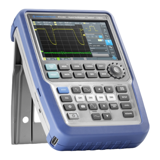
® Instrument Tour R&S Scope Rider RTH Front View Instrument Tour Front View Figure 3-1: Front panel of the R&S RTH1002 1 = Touch display 2 = Waveform setup with AUTOSET, reset to default with PRESET 3 = Analysis functions 4 = Mode selection 5 = Save/Recall 6 = Instrument settings... - Page 44 ® Instrument Tour R&S Scope Rider RTH Front View 11 = Acquisition settings 12 = Screenshot and documentation output 13 = Channels and vertical settings 14 = Multimeter measurements Figure 3-2: Front panel of the R&S RTH1004 1 = Touch display 2 = Waveform setup with AUTOSET, reset to default with PRESET 3 = Analysis functions 4 = Mode selection...
-
Page 45: Top View
® Instrument Tour R&S Scope Rider RTH Top View For a description of the keys, see Chapter 4.3.3, "Using Front Panel Keys", on page 33. Top View The R&S RTH1002 has two BNC input connectors CH1 and CH2, and two 4mm banana plug inputs for various multimeter measurements. - Page 46 ® Instrument Tour R&S Scope Rider RTH Top View Shock hazard caused by high voltages To avoid electrical shock and personal injury, and to prevent damage to the instrument or any other products connected to it, observe the following: ● Do not apply input voltages above the rating of the instrument and the accessories.
-
Page 47: Right View
® Instrument Tour R&S Scope Rider RTH Right View Right View 1 = LAN 2 = USB type B for remote control 3 = Probe compensation 4 = USB type A for flash drive 5 = Logic probe connector Risk of injury or instrument damage Always close the lids of the communication ports and DC input when they are not in use. -
Page 48: Left View
® Instrument Tour R&S Scope Rider RTH Left View Logic probe connector Input for the logic probe R&S RT-ZL04. Logic analysis requires Mixed Signal Option R&S RTH-B1, which includes the logic probe R&S RT-ZL04. Risk of electrical shock - no CAT rating for MSO measurements The logic probe R&S RT-ZL04 is not rated for any measurement category. -
Page 49: Display Overview
® Instrument Tour R&S Scope Rider RTH Display Overview Display Overview In the most important modes scope, mask and XY, the display shows the follow- ing information. 1 = Measurement results, depends on the mode and the selected measurement 2 = Time scale (horizontal scale, in s/division) 3 = Trigger type, trigger source, and trigger mode 4 = Capture status 5 = Battery status and AC connectivity for battery charging;... -
Page 50: Operating The Instrument
® Operating the Instrument R&S Scope Rider RTH Connecting Probes Operating the Instrument Connecting Probes Shock hazard caused by high voltages Make sure to set the attenuation factor on the instrument according to the probe being used. Otherwise, the measurement results do not reflect the actual voltage level, and you might misjudge the actual risk. -
Page 51: Connecting Test Leads (R&S Rth1002)
® Operating the Instrument R&S Scope Rider RTH Accessing the Functionality the probe. For example, if a 1 Ω resistor and a 10:1 probe is used, the V/A- value of the resistor is 1 V/A, the attenuation factor of the probe is 0.1, and the resulting current probe attenuation is 100 mV/A. - Page 52 ® Operating the Instrument R&S Scope Rider RTH Accessing the Functionality Figure 4-2: Open the menu and select a menu item Figure 4-3: Switch on or off (left) and select a parameter value (right) Getting Started 1326.1561.02 ─ 0301...
-
Page 53: Using The Navigation Wheel
® Operating the Instrument R&S Scope Rider RTH Accessing the Functionality Figure 4-4: Enter numerical value and unit 4.3.2 Using the Navigation Wheel In addition or alternatively to the touchscreen, you can use the wheel to control the R&S RTH. When using the wheel, always observe the position of the focus - the orange frame or other highlighting that marks the active object on the screen. - Page 54 ® Operating the Instrument R&S Scope Rider RTH Accessing the Functionality Menu navigation The following procedure describes how to access and navigate the menu. Navi- gating dialogs and selecting parameter values works in the same way. See also Figure 4-5. 1.
- Page 55 ® Operating the Instrument R&S Scope Rider RTH Accessing the Functionality 2. Turn the wheel until the required value is shown. 3. Press BACK. Figure 4-6: Set numerical value using the wheel Data entry using wheel and keypad You can enter enter precise numerical values on the keypad. See also Figure 4-7.
- Page 56 ® Operating the Instrument R&S Scope Rider RTH Accessing the Functionality Figure 4-7: Enter numerical value and unit in the keypad Getting Started 1326.1561.02 ─ 0301...
-
Page 57: Using Front Panel Keys
® Operating the Instrument R&S Scope Rider RTH Accessing the Functionality The SHIFT button toggles the wheel focus in the keypad. If the focus is on the entry field, turning the wheel changes the value. If the focus is in the lower part, the wheel selects numbers and unit. - Page 58 ® Operating the Instrument R&S Scope Rider RTH Accessing the Functionality Short press Long press SHIFT opens a dialog to save and load instrument settings. If a dialog or menu is open, BACK closes it. If the menu is closed, the key toggles the focus between focused element in the diagram and the Menu button.
-
Page 59: Displaying An Unknown Signal
® Operating the Instrument R&S Scope Rider RTH Displaying an Unknown Signal Short press Long press SIGNAL OFF switches the focused wave- form off. RUN STOP starts and stops the acquisition. SETUP opens or closes the "Trigger" dialog to select the trigger type and adjust the trigger settings. -
Page 60: Selecting The Mode
® Operating the Instrument R&S Scope Rider RTH Setting the Date, Time and Language Selecting the Mode A mode comprises all settings and functions that are needed to perform a mea- surement task. Selecting the mode is the first setup step. 1. -
Page 61: Getting Information And Help
® Operating the Instrument R&S Scope Rider RTH Getting Information and Help Set date and time Set display language Getting Information and Help In most dialogs, graphics explain the meaning of the selected setting. For further information, you can open the help, which provides functional description of the settings with links to the corresponding remote commands, and background infor- mation. -
Page 62: Displaying Help
® Operating the Instrument R&S Scope Rider RTH Getting Information and Help 4.7.1 Displaying Help ● "To open the help window" on page 38 ● "To show information on a setting" on page 38 ● "To close the help window" on page 39 To open the help window ►... -
Page 63: Using The Help Window
® Operating the Instrument R&S Scope Rider RTH Getting Information and Help If you tap the switch or the entry field, you can adjust the setting without clos- ing the help window. To close the help window ► Tap the "Close" icon in the upper right corner of the help window, or press BACK. - Page 64 ® Operating the Instrument R&S Scope Rider RTH Getting Information and Help ● Left and right arrows: browse the topics visited before: Left = back, right = for- ward. ● Magnifiers: increase or decrease the font. ● ×: closes the help window. To search for a topic in the index The index is sorted alphabetically.
-
Page 65: Maintenance
® Maintenance R&S Scope Rider RTH Cleaning Maintenance The instrument does not need a periodic maintenance. Only cleaning the instru- ment is essential. The addresses of the Rohde & Schwarz support centers can be found at www.customersupport.rohde-schwarz.com. A list of service centers is available on www.services.rohde-schwarz.com. Cleaning Shock hazard Before cleaning the instrument, remove all probes, leads, USB and LAN... -
Page 66: Data Storage And Security
® Maintenance R&S Scope Rider RTH Storing and Packing Data Storage and Security The instrument is delivered with the 4 Gbyte microSD card inserted and ready to use. We recommend that you do not remove the microSD card. All instrument configuration data and user data are stored on the microSD card. In addition, a fallback firmware is stored on the microSD card to boot the instru- ment if an update failed.
Need help?
Do you have a question about the RTH1054MSO and is the answer not in the manual?
Questions and answers