Rohde & Schwarz RTH1002 Getting Started
Handheld digital
oscilloscope
Hide thumbs
Also See for RTH1002:
- User manual (530 pages) ,
- Getting started (81 pages) ,
- Getting started (53 pages)
Table of Contents
Advertisement
Quick Links
Download this manual
See also:
User Manual
Advertisement
Table of Contents

Related Manuals for Rohde & Schwarz RTH1002


Summary of Contents for Rohde & Schwarz RTH1002
- Page 1 ® R&S Handheld Digital Oscilloscope Getting Started (=J?Ë2) 1326.1561.02 ─ 03...
- Page 2 ® This manual describes the following R&S RTH models: ● R&S ® RTH1002 (1317.5000.K02) ● R&S ® RTH1004 (1317.5000.K04) This manual is available in various languages for download from the R&S RTH product page at www.rohde-schwarz.com/product/rth.html > "Downloads > Man- uals".
-
Page 3: Table Of Contents
3.3 Right View....................23 3.4 Left View....................24 3.5 Display Overview................25 4 Operating the Instrument............26 4.1 Connecting Probes................26 4.2 Connecting Test Leads (R&S RTH1002)........... 27 4.3 Accessing the Functionality.............. 27 4.3.1 Using the Touchscreen................. 27 Getting Started 1326.1561.02 ─ 03... - Page 4 ® Contents R&S 4.3.2 Using the Navigation Wheel..............29 4.3.3 Using Front Panel Keys................ 33 4.4 Displaying an Unknown Signal............35 4.5 Selecting the Mode................36 4.6 Setting the Date, Time and Language..........36 4.7 Getting Information and Help............37 4.7.1 Displaying Help..................38 4.7.2 Using the Help Window.................39 5 Maintenance.................
-
Page 5: Key Features And Key Specifications
● Logic analyzer with 8 digital inputs (optional) ● Protocol analyzer with trigger and decode (optional) ● Data logger ● Digital multimeter (R&S RTH1002) Main Specifications This chapter lists the main characteristics of the R&S RTH. The complete specifi- cations are listed in the Data Sheet, see chapter 1.5, "Documentation... - Page 6 60 MHz, 100 MHz, 200 MHz, 350 MHz, 500 MHz ● Rise time (calculated): R&S RTH1002 and R&S RTH1004 with bandwidth of 60 MHz, 100 MHz, 200 MHz, 350 MHz, 500 Mhz: < 5.8 ns, < 3.5 ns, < 1.75 ns, < 1 ns, < 700 ps (meas.) respectively...
- Page 7 ● Mask testing with up to 5 simultaneous masks ● Waveform mathematics ● Data logger ● True RMS Digital Multimeter (R&S RTH1002 only) – Resolution: 4 digits, 10.000 counts – Measurements: voltage: DC, AC, AC+DC; resistance, continuity test, diode test, capacitance, temperature (with optional accessory), frequency, cur- rent (with optional accessory) ●...
- Page 8 Safety compliance ● IEC / EN / DIN EN 61010-1 ● IEC / EN / DIN EN 61010-2-030 ● IEC / EN / DIN EN 61010-2-033 (R&S RTH1002) ● UL / CSA 61010-1 ● UL / CSA 61010-2-030 ● UL / CSA 61010-2-033 (R&S RTH1002)
-
Page 9: Input Isolation
® Key Features and Key Specifications R&S Input Isolation EMC compliance ● RF emission – In line with CISPR 11 / EN 55011 group 1 class A (for a shielded test setup) – Complies with the emission requirements stipulated by EN 55011, EN 61326-1 and EN 61326-2-1 class A, making the instrument suitable for use in industrial environments ●... -
Page 10: Measurement Categories
® Key Features and Key Specifications R&S Measurement Categories ● The risk of causing a short circuit while measuring multiple signals is reduced substantially. ● When measuring signals with different grounds, the induced ground currents are kept to a minimum. Measurement Categories To ensure safe operation of measurement instruments, IEC 61010-2-030 defines particular safety requirements for testing and measuring circuits. -
Page 11: Documentation Overview
® Key Features and Key Specifications R&S Documentation Overview Fig. 1-2: Examples of measurement categories The higher the category, the higher the expected transient overvoltage. Overvol- tages can overload a circuit and cause electrical and physical damage. Therefore, use the measurement instrument only in electrical environments for which the instrument is rated. -
Page 12: Regulatory Information
® Key Features and Key Specifications R&S Regulatory Information in other languages, as well as newest version of the English one, are available on the product page. ● User Manual The user manual describes all instrument modes and functions in detail. It also provides an introduction to remote control and a complete description of the remote control commands with programming examples. - Page 13 ® Key Features and Key Specifications R&S Regulatory Information ● this device must accept any interference received, including interference that may cause undesired operation. Le présent appareil est conforme aux CNR d'Industrie Canada applicables aux appareils radio exempts de licence. L'exploitation est autorisée aux deux condi- tions suivantes: ●...
-
Page 14: Preparing For Use
® Preparing for Use R&S Preparing for Use This section describes the basic steps to be taken when setting up the R&S RTH for the first time. Shock hazard caused by high voltages The instrument must be used in an appropriate manner to prevent electric shock, fire, personal injury, or damage. -
Page 15: Unpacking The Instrument
● Power adapter with cable and adapter set for various socket types ● Battery pack ● Probes (2x for R&S RTH1002; 4x for R&S RTH1004) ● DMM test leads (only for R&S RTH1002) ● Hand strap, attached on the handheld scope ●... -
Page 16: Inserting And Charging The Battery
® Preparing for Use R&S Inserting and Charging the Battery Inserting and Charging the Battery Before you can use the handheld scope for the first time, insert the battery pack and charge it. Risk of electrical shock during battery replacement ●... - Page 17 ® Preparing for Use R&S Inserting and Charging the Battery 1. Fold out the tilt stand on the back of the instrument. 2. Screw open the battery cover. 3. Insert the battery pack. 4. Screw down the battery cover. 5. Connect the power adapter to the connector on the left side of the scope, and fully charge the battery.
-
Page 18: Powering On/Off
® Preparing for Use R&S Powering On/Off Powering On/Off ► Press the POWER key to switch the instrument on or off. The POWER key lights up in green color if power is on. Using the Tilt Stand The R&S RTH has a tilt stand for proper handling while the scope is placed on a table. -
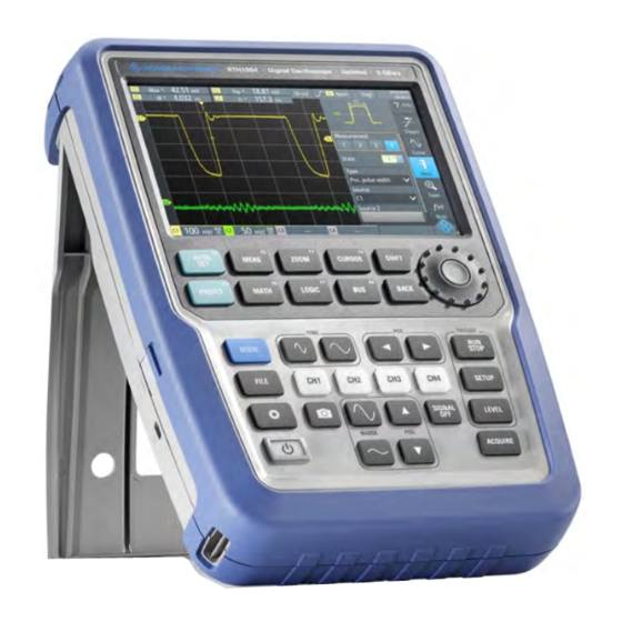
Page 19: Instrument Tour
Instrument Tour R&S Front View Instrument Tour Front View Fig. 3-1: Front panel of the R&S RTH1002 1 = Touch display 2 = Waveform setup with Autoset, reset to default with PRESET 3 = Analysis functions 4 = Mode selection... - Page 20 ® Instrument Tour R&S Front View 11 = Acquisition settings 12 = Screenshot and documentation output 13 = Channels and vertical settings 14 = Multimeter measurements Fig. 3-2: Front panel of the R&S RTH1004 1 = Touch display 2 = Waveform setup with Autoset, reset to default with PRESET 3 = Analysis functions 4 = Mode selection 5 = Save/Recall...
-
Page 21: Top View
33. Top View The R&S RTH1002 has two BNC input connectors CH1and CH2, and two 4mm banana plug inputs for various multimeter measurements: voltage DC / AC / AC +DC, resistance, continuity test, diode test, capacitance, temperature, and fre- quency. - Page 22 ® Instrument Tour R&S Top View Shock hazard caused by high voltages To avoid electrical shock and personal injury, and to prevent damage to the instrument or any other products connected to it, observe the following: ● Do not apply input voltages above the rating of the instrument and the accessories.
-
Page 23: Right View
® Instrument Tour R&S Right View Right View 1 = LAN 2 = USB type B for remote control 3 = Probe compensation 4 = USB type A for flash drive and mouse 5 = Logic probe connector Risk of injury or instrument damage Always close the lids of the communication ports and DC input when they are not in use. -
Page 24: Left View
® Instrument Tour R&S Left View Logic probe connector Input for the logic probe R&S RT-ZL04. Logic analysis requires Mixed Signal Option R&S RTH-B1, which includes the logic probe R&S RT-ZL04. Risk of electrical shock - no CAT rating for MSO measurements The logic probe R&S RT-ZL04 is not rated for any measurement category. -
Page 25: Display Overview
® Instrument Tour R&S Display Overview Display Overview In the most important modes scope, mask and XY, the display shows the follow- ing information. 1 = Measurement results, depends on the mode and the selected measurement 2 = Time scale (horizontal scale, in s/division) 3 = Trigger type, trigger source, and trigger mode 4 = Capture status 5 = Battery status and AC connectivity for battery charging;... -
Page 26: Operating The Instrument
® Operating the Instrument R&S Connecting Probes Operating the Instrument Connecting Probes Shock hazard caused by high voltages Make sure to set the attenuation factor on the instrument according to the probe being used. Otherwise, the measurement results do not reflect the actual voltage level, and you might misjudge the actual risk. -
Page 27: Connecting Test Leads (R&S Rth1002)
1 V/A, the attenuation factor of the probe is 0.1, and the resulting current probe attenuation is 100 mV/A. Connecting Test Leads (R&S RTH1002) The R&S RTH1002 has an integrated digital multimeter (DMM) and test leads for multimeter measurements. Fig. 4-1: Meter inputs to connect test leads 1. - Page 28 ® Operating the Instrument R&S Accessing the Functionality Fig. 4-2: Open the menu and select a menu item Fig. 4-3: Switch on or off (left) and select a parameter value (right) Getting Started 1326.1561.02 ─ 03...
-
Page 29: Using The Navigation Wheel
® Operating the Instrument R&S Accessing the Functionality Fig. 4-4: Enter numerical value and unit 4.3.2 Using the Navigation Wheel In addition or alternatively to the touchscreen, you can use the wheel to control the R&S RTH. When using the wheel, always observe the position of the focus - the orange frame or other highlighting that marks the active object on the screen. - Page 30 ® Operating the Instrument R&S Accessing the Functionality Menu navigation The following procedure describes how to access and navigate the menu. Navi- gating dialogs and selecting parameter values works in the same way. See also figure 4-5. 1. Press BACK until the focus is on the "Menu" button. 2.
- Page 31 ® Operating the Instrument R&S Accessing the Functionality Data entry The following procedure describes how to enter numerical values on the keypad. See also figure 4-6. 1. Set the focus to the required menu item and press the wheel button. 2.
- Page 32 ® Operating the Instrument R&S Accessing the Functionality Fig. 4-6: Enter numerical value and unit Getting Started 1326.1561.02 ─ 03...
-
Page 33: Using Front Panel Keys
® Operating the Instrument R&S Accessing the Functionality 4.3.3 Using Front Panel Keys For an overview of the front panel keys, see figure 3-2 Short press Long press AUTOSET analyses the active channels, adjusts the instrument settings, and displays stable waveforms. PRESET sets the instrument to the default factory state. - Page 34 If the channel has the focus, the key switches the channel off. Only DMM starts or stops the meter measure- Opens or closes the "Meter" R&S RTH1002: ments (same as MODE = "Meter"). dialog to configure the mea- surements. DMM REL enables or disables relative meter measurements.
-
Page 35: Displaying An Unknown Signal
® Operating the Instrument R&S Displaying an Unknown Signal Short press Long press SETUP opens or closes the "Trigger" dialog to select the trigger type and adjust the trigger settings. LEVEL activates the trigger level to be set using the wheel. If the trigger type has two trigger levels, pressing the key toggles the upper and lower levels. -
Page 36: Selecting The Mode
® Operating the Instrument R&S Selecting the Mode Selecting the Mode A mode comprises all settings and functions that are needed to perform a mea- surement task. Selecting the mode is the first setup step. 1. Press the MODE key. 2. -
Page 37: Getting Information And Help
® Operating the Instrument R&S Getting Information and Help Set date and time Set display language Getting Information and Help In most dialogs, graphics explain the meaning of the selected setting. For further information, you can open the help, which provides functional description of the settings with links to the corresponding remote commands, and background infor- mation. -
Page 38: Displaying Help
® Operating the Instrument R&S Getting Information and Help 4.7.1 Displaying Help ● "To open the help window" on page 38 ● "To show information on a setting" on page 38 ● "To close the help window" on page 39 To open the help window ►... -
Page 39: Using The Help Window
® Operating the Instrument R&S Getting Information and Help If you tap the switch or the entry field, you can adjust the setting without clos- ing the help window. To close the help window ► Tap the "Close" icon in the upper right corner of the help window, or press BACK. - Page 40 ® Operating the Instrument R&S Getting Information and Help ● Left and right arrows: browse the topics visited before: Left = back, right = for- ward. ● Magnifiers: increase or decrease the font. ● ×: closes the help window. To search for a topic in the index The index is sorted alphabetically.
-
Page 41: Maintenance
® Maintenance R&S Cleaning Maintenance The instrument does not need a periodic maintenance. Only cleaning the instru- ment is essential. The addresses of the Rohde & Schwarz support centers can be found at www.customersupport.rohde-schwarz.com. A list of service centers is available on www.services.rohde-schwarz.com. Cleaning Shock hazard Before cleaning the instrument, remove all probes, leads, USB and LAN... -
Page 42: Data Storage And Security
® Maintenance R&S Data Storage and Security Data Storage and Security The instrument is delivered with the 4 GByte SD card inserted and ready to use. We recommend that you do not remove the SD card. All instrument configuration data and user data are stored on the SD card. In addition, a fallback firmware is stored on the the SD card to boot the instrument if an update failed.
Need help?
Do you have a question about the RTH1002 and is the answer not in the manual?
Questions and answers