Rohde & Schwarz R&S RTB2000 Series Getting Started
Digital oscilloscope
Hide thumbs
Also See for R&S RTB2000 Series:
- User manual (547 pages) ,
- Getting started (19 pages) ,
- Manual (2 pages)
Table of Contents
Advertisement
Advertisement
Table of Contents

Related Manuals for Rohde & Schwarz R&S RTB2000 Series


Summary of Contents for Rohde & Schwarz R&S RTB2000 Series
- Page 1 ® R&S RTB2000 Digital Oscilloscope Getting Started (=Q@52) 1333.1605.02 ─ 05...
- Page 2 ® This manual describes the following R&S RTB2000 models: ● ® R&S RTB2002 (1333.1005K02) ● ® R&S RTB2004 (1333.1005K04) © 2018 Rohde & Schwarz GmbH & Co. KG Mühldorfstr. 15, 81671 München, Germany Phone: +49 89 41 29 - 0 Fax: +49 89 41 29 12 164 Email: info@rohde-schwarz.com...
-
Page 3: Table Of Contents
® Contents R&S RTB2000 Contents 1 For Your Safety..................5 2 Documentation Overview..............7 Manuals and Instrument Help..................7 Data Sheet and Brochure..................... 8 Calibration Certificate....................8 Release Notes and Open Source Acknowledgment..........8 3 Preparing for Use................... 9 Unpacking and Checking the Instrument..............9 Positioning the Instrument...................9 Starting the Instrument....................10 3.3.1... - Page 4 ® Contents R&S RTB2000 Getting Started 1333.1605.02 ─ 05...
-
Page 5: For Your Safety
® For Your Safety R&S RTB2000 1 For Your Safety The R&S RTB2000 digital oscilloscope is designed for measurements on circuits that are only indirectly connected to the mains or not connected at all. It is not rated for any measurement category. - Page 6 ® For Your Safety R&S RTB2000 Risk of instrument damage An unsuitable operating site or test setup can damage the instrument and connected devices. Ensure the following operating conditions before you switch on the instrument: ● Read and observe the "Basic Safety Instructions" brochure and the safety instruc- tions in the manuals.
-
Page 7: Documentation Overview
® Documentation Overview R&S RTB2000 Manuals and Instrument Help 2 Documentation Overview This section provides an overview of the R&S RTB2000 user documentation. 2.1 Manuals and Instrument Help You find the manuals on the product page at: www.rohde-schwarz.com/manual/rtb2000 Getting started manual Introduces the R&S RTB2000 and describes how to set up the product. -
Page 8: Data Sheet And Brochure
® Documentation Overview R&S RTB2000 Release Notes and Open Source Acknowledgment 2.2 Data Sheet and Brochure The data sheet contains the technical specifications of the R&S RTB2000. It also lists the options with their order numbers and optional accessories. The brochure provides an overview of the instrument and deals with the specific characteristics. -
Page 9: Preparing For Use
® Preparing for Use R&S RTB2000 Positioning the Instrument 3 Preparing for Use 3.1 Unpacking and Checking the Instrument 1. Inspect the package for damage. If the packaging material shows any signs of stress, notify the carrier who delivered the instrument. 2. -
Page 10: Starting The Instrument
® Preparing for Use R&S RTB2000 Starting the Instrument Risk of injury if feet are folded out The feet can fold in if they are not folded out completely or if the instrument is shifted. This can cause damage or injury. ●... -
Page 11: Starting Up And Shutting Down
® Preparing for Use R&S RTB2000 Starting the Instrument ● max. 60 W Risk of injury Connect the instrument only to an outlet that has a ground contact. Do not use an isolating transformer to connect the instrument to the AC power supply. 1. -
Page 12: Powering Off
® Preparing for Use R&S RTB2000 Replacing the Fuse All current settings are saved, and the software shuts down. Now it is safe to power off the instrument. 3.3.3 Powering Off Powering off is required only if the instrument must be disconnected from all power supplies. -
Page 13: Instrument Tour
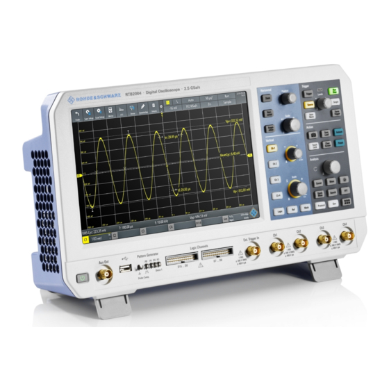
® Instrument Tour R&S RTB2000 Front Panel 4 Instrument Tour 4.1 Front Panel Figure 4-1 shows the front panel of the R&S RTB2000. The function keys are grouped in functional blocks to the right of the display. Figure 4-1: Front panel of R&S RTB2004 with 4 input channels 1 = Display 2 = Horizontal and vertical setup controls 3 = Trigger settings, action and analysis controls... -
Page 14: Input Connectors
® Instrument Tour R&S RTB2000 Front Panel 4.1.1 Input Connectors BNC inputs (4 and 5) The R&S RTB2000 has two or four channel inputs (4) to connect the input signals. The external trigger input (5) is used to control the measurement by an external signal. The trigger level can be set from -5 V to 5 V. -
Page 15: Other Connectors On The Front Panel
® Instrument Tour R&S RTB2000 Rear Panel Logic probe (6) The connectors for logic channels can be used if the Mixed Signal Option R&S RTB-B1 is installed. The option provides connectors for two logical probes with 8 digital chan- nels each (D0 to D7 and D8 to D15). The maximum input voltage is 40 V (peak) at 100 kΩ... - Page 16 ® Instrument Tour R&S RTB2000 Rear Panel Figure 4-2: Rear panel view of R&S RTB2000 1 = LAN connector 2 = USB connector, type B 3 = AC power supply connector and main power switch 4 = Kensington lock slot to secure the instrument against theft 5 = Loop for lock to secure the instrument against theft 6 = not used LAN (1)
Need help?
Do you have a question about the R&S RTB2000 Series and is the answer not in the manual?
Questions and answers