
Related Manuals for Excalibur KE-170


Summary of Contents for Excalibur KE-170
- Page 1 KE-170 DELUXE KEyLESS ENTRy SySTEM OWNER’S & INSTALLATION MANUAL (production manual has full color cover) This product is designed for professional installation only! COPYRIGHT: OMEGA RESEARCH & DEVELOPMENT 2016...
-
Page 2: Table Of Contents
Changing The Programmable Features ..........17 Full System Reset ................18 Programming Transmitters ..............18 Ordering Replacement Transmitters ..........19 Installation Considerations ..............20 Mounting components................20 Wiring Connections ................21 Main 12 pin harness................21 Door Lock Connections..............23 Driver’s Door Priority Connection ............27 KE-170 Wiring Overview ...............29 Programmable Features List ..............30... -
Page 3: System Overview
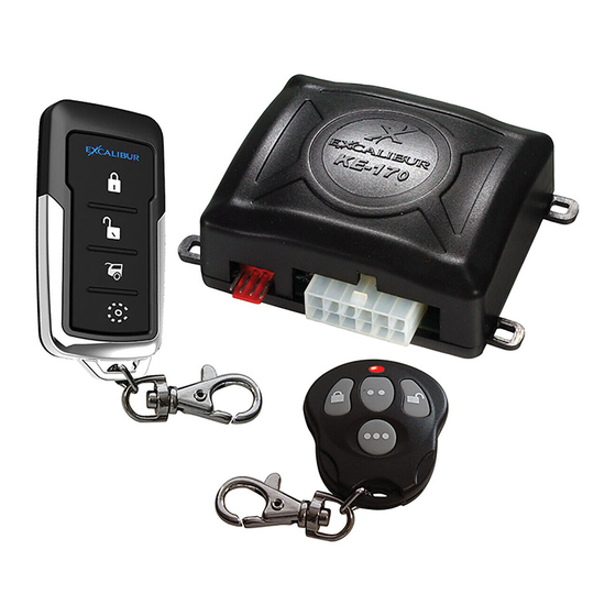
System Overview The 2 system components used to control and monitor this system: The Transmitter: Each system comes with 2 pre-learned transmitters. This system can be operated by up to 4 different transmitters. Each transmitter is embedded with a unique security code and can only operate one system at a time. -
Page 4: The 1-Way Transmitter
Transmitter Overview “unlock” THE 1-WAy TRANSMITTERS button Battery: 2 x CR2016 “lock” Frequency: 433MHz button Call your dealer or visit “unlock” www.caralarm.com to button order replacement transmitters. “trunk” Transmitter battery replacement: Transmitter battery replacement: button Remove the small screw from “3rd Ch”... - Page 5 UNLOCK: Press and release the “UNLOCK” button. • THE HORN WILL HONK TWICE • THE LIGHTS WILL FLASH TWICE THEN TURN ON • THE DOORS WILL UNLOCK* • THE OPTIONAL STARTER INTERRUPT WILL DISARM * IF THE SYSTEM IS CONFIGURED FOR DRIVER’S PRIORITY, ONLY THE DRIVER’S DOOR WILL UNLOCK.
- Page 6 Transmitter Functions Reference guide (cont’d) PANIC: Press and hold the “LOCK” or “UNLOCK” button for 3 seconds. • THE DOORS WILL LOCK OR UNLOCK • THE HORN WILL HONK CONTINUOUSLY • THE LIGHTS WILL FLASH CONTINUOUSLY - OR - ACTIVATE 4TH CHANNEL: Press and release the “LOCK” & “UNLOCK” buttons simultaneously.
- Page 7 ACTIVATE 5TH CHANNEL: Press and release the “TRUNK” & “3RD CH” but- tons simultaneously. Consult your installer about this optional feature. • THERE IS NO VISUAL OR AUDIBLE INDICATION FROM THIS SYSTEM. IF CONNECTED TO AN OPTIONAL ACCESSORY, THAT ACCESSORY MAY PROVIDE VISUAL/AUDIBLE CONFIRMATION WHEN ACTIVATED.
-
Page 8: Using The Status Light/Valet Button
When the system enters Valet Mode, the Status Light will stay on. If the KE-170 is installed with audible confirmation, the system will chirp twice when it enters Valet Mode. Remember to check the Status Light - if it is not illuminated or flashing fast, the system may be placed into Valet Mode. - Page 9 CH“ buttons will still operate - but the optional Starter Interrupt will not operate, and any programmed automatic functions are suspended. To exit Valet Mode simply press and release the Status Light/Valet Button at any time; the Status Light will turn off. System Override: If the last system operation was locking the doors by the transmitter, a System Override is required before placing the system into Valet Mode, or starting the engine if the optional Starter Interrupt is installed.
-
Page 10: The Status Light
The Status Light The KE-170’s Status Light/Valet Button is a combined Valet/Override button & Status Light to inform you of the system’s operational condition. If your system includes a Starter Interrupt circuit, it’s condition is also reflected in this light’s operation, along with any automatic features which may have been programmed to operate. -
Page 11: Visual Confirmations
Visual Confirmations The KE-170 is capable of flashing the vehicle’s parking lights and inte- rior domelight to provide visual confirmation of system operations. Flash Once - The doors have been locked and the (optional) starter interrupt is enabled. Flash Twice, Then Illuminate for 30 Seconds - Doors have been unlocked via the transmitter and the (optional) starter interrupt is disabled. -
Page 12: Starter Interrupt - Optional
Audible Confirmations (cont’d) If the system is in Valet Mode, it will also chirp once when the ignition is turned “OFF” as a reminder. Should any automatic locking options be enabled, the system will chirp once to indicate the doors locking. Remote “PANIC”: Connecting the audible output to the vehicle’s horn adds a valuable safety feature. -
Page 13: Programmable Features
Programmable Features The KE-170 has 12 programmable features for maximum system cus- tomization. The following pages describe each feature and its available options. Feature #1 - Doors Lock 90 Seconds After the Ignition is Turned OFF (press LOCK to program) (press UNLOCK to program) - DEFAULT This feature will automatically lock the doors 90 seconds after the ignition key is turned off. - Page 14 Programmable Features (cont’d) Feature #4 - Doors Unlock When Trunk Release is Activated (press LOCK to program) - DEFAULT (press UNLOCK to program) This feature will automatically unlock the doors whenever the trunk release is activated to offer extra convenience. It can be turned off if the output is used for another function. Feature #5 - Door Lock/Unlock Pulse Timing 0.8 Second (press LOCK to program) - DEFAULT...
- Page 15 Feature #7 - WHITE & WHITE/BLACK Wires Function Flashing lights (press LOCK to program) - DEFAULT 5th Channel Single Pulse (press UNLOCK to program) 5th Channel Latch/Unlatch (press TRUNK to program) Horn Honk Output (press 3RD CH to program) This feature changes the operation of the flashing light outputs. It can be configured as a 5th chan- nel output for additional accessories if needed and you can select from a pulsed or latching output.
- Page 16 Programmable Features (cont’d) Feature #10 - Anti-Carjacking Ign Activated Anti-Carjacking (press LOCK to program) Remote Activated Anti-Carjacking (press UNLOCK to program) Ign & Remote Activated Anti-Carjacking (press TRUNK to program) (press 3RD CH to program) - DEFAULT This system offers 2 forms of anti-carjacking protection. One is automatically activated when the igntion is turned on.
-
Page 17: Changing The Programmable Features
Feature #11 - Parking Lights for 30 Seconds After Unlock by Transmitter (press LOCK to program) - DEFAULT (press UNLOCK to program) This feature is defaulted so the flashing light output will stay on for 30 seconds after remotely unlocking the doors. Feature #12 - “3RD CH“... -
Page 18: Full System Reset
Changing The Programmable Features (cont’d) STEP 4 - Press the transmitter button that corresponds to the setting you desire. The horn will honk 1 time for LOCK, 2 times for UNLOCK, 3 times for TRUNK, and 4 times for “3RD CH“. STEP 5 - Repeat steps 3 and 4 if you need to change more than one feature. -
Page 19: Ordering Replacement Transmitters
STEP 3 - Press the LOCK button on the 1st transmitter to be programmed. The horn will honk once and the status light will flash 2 times (once to indicate transmitter learn mode & once to indicate the 1st transmtter) STEP 4 - Repeat STEP 3 for each additional transmitter. -
Page 20: Installation Considerations
Installation Considerations MOUNTINg COMPONENTS The Control Module: This contains electronic components so always mount this module at a secure location inside the vehicle like under the dash. Ensure that the module is not succeptable to moisture, excessive vibration, or exces- sive temperatures (like next to heater hoses). -
Page 21: Wiring Connections
Wiring Connections MAIN 12 PIN HARNESS BLACK: (-) Chassis ground- This wire supplies ground for all of the system’s operations. Connect this wire to the metal structure of the vehicle, preferably using an existing machine screw or bolt. Cut the wire to the shortest practical length and crimp on a proper sized ring terminal. - Page 22 Wiring Connections (cont’d) yELLOW/gREEN: (-) OEM Alarm Disarm Output- This wire mimics the BLUE unlock wire and is used for disarming factory installed alarm systems. It is a 250mA negative output. BROWN/BLACK: (-) Horn Honk Output- Connect this to the vehicle’s horn switch circuit.
-
Page 23: Door Lock Connections
4th channel or 2nd light flash using feature # 6. DOOR LOCK CONNECTIONS The KE-170 has a 4 pin plug-in door lock/unlock port. It provides 3 250mA outputs for LOCK, UNLOCK #1 (driver’s OR all doors), and UNLOCK #2 (all doors for driver’s priority). - Page 24 Wiring Connections (cont’d) 3 Wire Negative Doorlocks With All Unlock Function Pink Wire - NOT USED Using Included DLP-N4 Green Wire Blue Wire To (Standard Intallations) To Door Lock Wire Door Unlock Wire Unlock Lock Vehicle’s Doorlock Ground Doorlock Relay Control Unit Switch Doorlock 3 Wire Negative Doorlocks...
- Page 25 3 Wire Negative Doorlocks With All Unlock Function DLP-P3 Using Optional DLP-P3 Green Wire Blue Wire To To Door Lock Wire Door Unlock Wire Unlock Lock Vehicle’s Doorlock Doorlock +12V Relay Control Unit Switch Doorlock 3 Wire Positive Doorlocks Actuators With The Optional DLS And 2 SPDT Relays Relay...
- Page 26 Wiring Connections (cont’d) 5 Wire Reversal Doorlocks DLS Red connector Using The Optional plugs into Control DLS & 2 Relays Unit (wire colors are Relay Relay All Doorlock the same for other Actuators Omega interfaces) Violet wire to Constant (+) 12 Volts. Driver Passenger Doorlock...
-
Page 27: Driver's Door Priority Connection
DRIVER’S DOOR PRIORITy CONNECTION Everything described in the previous section also applies to configur- ing the driver’s door priority option. You would still connect the LOCK circuit as described but would utilize the PINK UNLOCK #2 output wire instead of the BLUE UNLOCK #1 output wire to activate the vehicle’s UNLOCK circuit. -
Page 28: Ke-170 Wiring Overview
KE-170 Wiring Overview gREEN: Lock (-) EMPTY BLUE: Unlock #1 (-) PINK: Unlock #2 (-) gREEN/VIOLET: Dome Light Relay (+/-) Output BROWN/BLACK: Horn Honk (-) Output BLACK/RED: Dome Light Relay (+/-) Input 15 AMP ORANgE: Starter Interrupt (-) Output PINK: #3 Channel (-) Output... - Page 29 Status Light/Valet Button Black Antenna Wire (stretch out fully for best range)
-
Page 30: Programmable Features List
Programmable Features List Complete Programmable Features Matrix Feature Programming: Ignition on, off, press valet 5 times (horn honks, status light turns on) # Feature Lock Button Trunk button Unlock button “3rd Ch” button 1 Lock 90 Sec After Ign Off 2 Lock 90 Sec After Unlock 3 Ign Lock/Unlock Lock &... - Page 31 This device complies with FCC Rules part 15. Operation is subject to the following two conditions, (1) This device may not cause harmful interference and, (2) This device must accept any interference that may be received, including interference that may cause undesired operation. The manufacturer is not responsible for any radio or TV interference caused by unauthorized modifications to this equipment.
- Page 32 L I M I T E D L I F E T I M E W A R R A N T y Products manufactured and sold by OMEGA RESEARCH & DEVELOPMENT, INC. (the Company), are warranted to be free from defects in materials and workmanship under normal use. If a product sold by the Company proves to be defective, the Company will repair or replace it free of charge within the first year and thereafter all parts to be repaired will be free with only a nominal charge for Omega Research and Development, Inc.’s labor and return shipping, to the original owner during the lifetime of the car in which it was originally installed.
Need help?
Do you have a question about the KE-170 and is the answer not in the manual?
Questions and answers