
Related Manuals for THORLABS PY004


Summary of Contents for THORLABS PY004
- Page 1 sales@artisantg.com artisantg.com (217) 352-9330 | Visit our website - Click HERE...
- Page 2 PY004 High Load Pitch Yaw Platform User Guide HA0292T...
-
Page 3: Table Of Contents
PY004 High Load Pitch Yaw Platform Contents Chaper 1 Safety ......................1 1.1 Safety Information ................1 1.2 General Warnings ................1 Chaper 2 Introduction ....................2 2.1 Description of the Pitch Yaw Platform ..........2 2.2 Micrometer Drives ................3 2.2.1 Reading Micrometer Drives .............. -
Page 4: Chaper 1 Safety
Chapter 1 Safety Chapter 1 Safety 1.1 Safety Information For the continuing safety of the operators of this equipment, and the protection of the equipment itself, the operator should take note of the Warnings, Cautions and Notes throughout this handbook and, where visible, on the product itself. The following safety symbols may be used throughout the handbook and on the equipment itself. -
Page 5: Chaper 2 Introduction
Chapter 2 Introduction 2.1 Description of the Pitch Yaw Platform The PY004 Pitch Yaw Platform provides ±2.5° of adjustment in pitch and ±4.05° in yaw. It was designed for use with up to 5 kg (11 lb) loads, such as lasers, cameras and 3-Axis stages (MBT6xx, MAX3xx). -
Page 6: Micrometer Drives
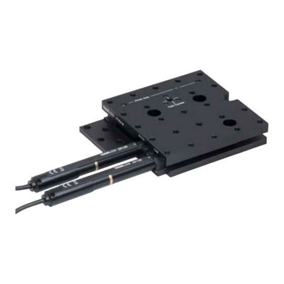
Chapter 2 Introduction Fig. 2.2 PY004Z8 Motorized Stage 2.2 Micrometer Drives 2.2.1 Reading Micrometer Drives Scale Index Mark working range 0 to 9 mid point 4.5 32.4 arcsec/division (0.45° per revolution) 18 arcsec/division (0.25° per revolution) Pitch Scale Index Mark working range 0 to 10 mid point 5 Fig. -
Page 7: Chaper 3 Installation And Operation
PY004 High Load Pitch Yaw Platform Chapter 3 Installation and Operation 3.1 Unpacking Caution Once removed from its packaging, the pitch yaw platform is easily damaged by mishandling. The unit should only be handled by its base, not by the top platform or any attachments to the top platform. -
Page 8: Mounting X And Y Axes In-Line With Hole Pattern
Chapter 3 Installation and Operation 3.2.1 Mounting X and Y Axes In-Line with Hole Pattern Y In Line Mounting Point Mounting Point X In Line Fig. 3.1 Mounting Both Axes In-Line with Hole Pattern 3.2.2 Mounting X Axis In-Line with Hole Pattern Y Off Centre Mounting Point CL Series... -
Page 9: Mounting Y Axis In-Line With Hole Pattern
PY004 High Load Pitch Yaw Platform 3.2.3 Mounting Y Axis In-Line with Hole Pattern Mounting Points X Off Centre Y In Line Fig. 3.3 Mounting Y Axis In-Line with Hole Pattern 3.3 Mounting Equipment to the Moving Platform The top platform features an array of 24 1/4”-20 or M6 threaded holes on a standard 25 mm or 1”... -
Page 10: Operation Using Apt Software
This section is applicable only to the PY004Z8(/M) stages, or stages fitted with Z812B actuators, when being driven by the APT software. 3.5.1 Compatible Drivers and Software The Thorlabs compatible controller for motorized PY004 stages is the K-Cube Single Channel DC Motor Controller KDC101. 3.5.2 System Setup To ensure that a particular stage is driven properly by the system, a number of parameters must first be set. - Page 11 PY004 High Load Pitch Yaw Platform 4) From the 'APT Configuration Utility' window, click the 'Stage' tab. Fig. 3.5 APT Configuration Utility - Stage Tab 5) In the ‘Motor’ field, select the serial number of the KDC101 controller associated with the Pitch axis (this number can be found on the rear panel of the controller unit).
-
Page 12: Homing Motors
Chapter 3 Installation and Operation 3.5.3 Homing Motors Homing the motor moves the actuator to the home limit switch then to its central position (as dictated by the zero offset parameter in the settings panel). The internal position counter and the GUI display are then set to zero. The limit switch provides a fixed datum that can be found after the system has been powered up. - Page 13 PY004 High Load Pitch Yaw Platform 6) Add the value noted at item (4) to the value (e.g. 8.2) currently shown in the Zero Offset field, and enter this new value. 7) Click OK to save the new setting. 8) Repeat items (1) to (7) for the other axis of the stage.
-
Page 14: Converting Linear To Rotational Units
Chapter 3 Installation and Operation 3.5.4 Converting Linear to Rotational Units The APT software for the Z812B motor actuator has been written to accept millimeters as the standard unit of translation. The relationship between movement of the motor lead screw in millimeters and movement of the stage platform in degrees (or arcseconds) is linear and the conversion factors are as follows: Pitch Movement in mm... - Page 15 PY004 High Load Pitch Yaw Platform Movement in mm Angle (arcsec) Angle (degree) -4.49 -14400 -4.0 4.49 14400 APT Input (mm) Page 12 ETN011941-D02...
-
Page 16: Operation Using Kinesis Software
This section is applicable only to the PY004Z8(/M) stages, or stages fitted with Z812B actuators, when being driven by the Kinesis software. 3.6.1 Compatible Drivers and Software The Thorlabs compatible controller for motorized PY004 stages is the K-Cube Single Channel DC Motor Controller KDC101. 3.6.2 System Setup To ensure that a particular stage is driven properly by the system, a number of parameters must first be set. - Page 17 PY004 High Load Pitch Yaw Platform 4) On startup, a window is displayed to select the stage being driven by the Z812 actuator. 5) Select PY004Z8 Pitch, or PY004Z8 Yaw as appropriate and click OK. Fig. 3.7 APT Configuration Utility - Stage Tab 6) A default configuration is set at the factory and stored in the non-volatile memory of the motor controller.
-
Page 18: Homing Motors
Chapter 3 Installation and Operation 3.6.3 Homing Motors Homing the motor moves the actuator to the home limit switch then to its central position (as dictated by the zero offset parameter in the settings panel). The internal position counter and the GUI display are then set to zero. The limit switch provides a fixed datum that can be found after the system has been powered up. - Page 19 PY004 High Load Pitch Yaw Platform 6) In the Device Startup Settings tab, click the ‘Select Actuator Type’ button and then select the ‘Add/Remove Custom Settings’ tab. Page 16 ETN011941-D02...
- Page 20 Chapter 3 Installation and Operation 7) Enter a suitable name in the Custom Name field, e.g. PY004Z8 Yaw (Custom) and click the Create Button. 8) Then click OK. The custom settings have been saved. 9) Click the Actuator Settings button. 10) Click the small black arrow next to the button to display the custom settings drop down box.
- Page 21 PY004 High Load Pitch Yaw Platform 13) Select the Enable Restricted settings checkbox. This must be checked to enable editing of the Restricted Parameters. This is a safeguard against accidentally editing Restricted Parameters in the Custom Device Startup Settings mode.
-
Page 22: Maintenance
Chapter 3 Installation and Operation 3.7 Maintenance 3.7.1 Regreasing Note Regreasing should be performed whenever the leadscrew thread appears dry or the motor is noisy. Periodic greasing is advised in applications with a high duty cycle, typically after 4000 cycles in pitch and/or 1800 cycles in yaw. 1) Drive both motors to extend the leadscrews to their full extent. -
Page 23: Chaper 4 Specification
Parameter Value Yaw ±4.05°, Pitch ±2.5° Adjustment Range Minimum Repeatable Incremental PY004(/M) Pitch: 9 arcsec, Yaw: 16.2 arcsec PY004Z8(/M) Pitch: 7.13 arcsec, Yaw: 15.71 arcsec Movement Pitch: 27.85 arcsec, Yaw: 4.75 arcsec Bi-directional Repeatability Pitch 1781 arcsec/s, Yaw 3142 arcsec/s... - Page 24 Chapter 4 Specification 2 kg (4.4 lb) Max 1 kg (2.2 lb) Max 5 kg (11 lb) Max Fig. 4.1 Spatial Load Specifications - Manual Stages 1 kg (2.2 lb) Max 2 kg (4.4 lb) Max Fig. 4.2 Spatial Load Specifications - Motorized Stages Rev F March 2021 Page 21...
-
Page 25: Chaper 5 Regulatory
PY004 High Load Pitch Yaw Platform Chapter 5 Regulatory 5.1 Declarations Of Conformity 5.1.1 For Customers in Europe See Section 5.2. 5.1.2 For Customers In The USA This equipment has been tested and found to comply with the limits for a Class A digital device, persuant to part 15 of the FCC rules. -
Page 26: Ce Declaration
Chapter 5 Regulatory 5.2 CE Declaration Page 23 Rev F Mar 2021... -
Page 27: Chaper 6 Thorlabs Worldwide Contacts
"End of life" units must be returned to Thorlabs or handed to a company specializing in waste recovery. Do not dispose of the unit in a litter bin or at a public waste disposal site. - Page 28 www.thorlabs.com...
Need help?
Do you have a question about the PY004 and is the answer not in the manual?
Questions and answers