Table of Contents
Advertisement
Quick Links
Advertisement
Table of Contents

Related Manuals for Datavideo PTC-140T


Summary of Contents for Datavideo PTC-140T
- Page 1 HDBASET PTZ CAMERA PTC-140T/PTC-140TH...
-
Page 2: Table Of Contents
Table of Contents FCC COMPLIANCE STATEMENT ..............5 WARNINGS AND PRECAUTIONS ..............5 WARRANTY ....................6 ..................6 TANDARD ARRANTY ..................7 HREE ARRANTY DISPOSAL ...................... 7 PRODUCT OVERVIEW ................9 ......................9 EATURES ....................10 XAMPLE ETUP LOCATION AND FUNCTION OF PARTS ..........11 ..................... - Page 3 IP ................... 40 TATIC DVIP ....................40 WEB USER INTERFACE ................. 44 .................... 44 REVIEW Control Functions ..................45 Preset ....................... 46 .................. 47 ONFIGURATION Audio Configure ..................47 Video Configure..................49 Video Encode ....................49 Stream Publish ....................52 RTP Multicast ....................
- Page 4 Disclaimer of Product and Services The information offered in this instruction manual is intended as a guide only. At all times, Datavideo Technologies will try to give correct, complete and suitable information. However, Datavideo Technologies cannot exclude that some information in this manual, from time to time, may not be correct or may be incomplete.
-
Page 5: Fcc Compliance Statement
7. This product should only be operated from the type of power source indicated on the marking label of the AC adapter. If you are not sure of the type of power available, consult your Datavideo dealer or your local power company. -
Page 6: Warranty
Warranty Standard Warranty Datavideo equipment are guaranteed against any manufacturing defects for one year from the date of purchase. The original purchase invoice or other documentary evidence should be supplied at the time of any request for repair under warranty. -
Page 7: Three Year Warranty
Camera module, PCIe Card are covered for 1 year. The three-year warranty must be registered on Datavideo's official website or with your local Datavideo office or one of its authorized distributors within 30 days of purchase. Disposal For EU Customers only - WEEE Marking... - Page 8 off your waste equipment for recycling, please contact your local city office, your household waste disposal service or the shop where you purchased the product. CE Marking is the symbol as shown on the left of this page. The letters "CE" are the abbreviation of French phrase "Conformité...
-
Page 9: Product Overview
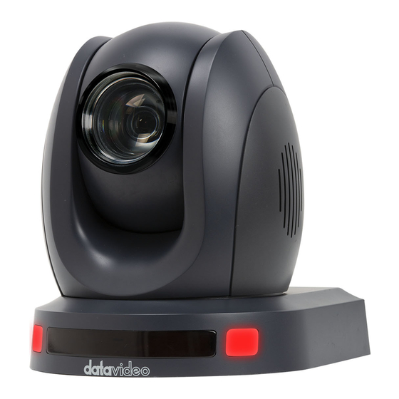
1. Product Overview The PTC-140T is a low-cost HDBT PTZ camera featuring PoE functionality, 20x optical zoom and 10x digital zoom. The camera is capable of transmitting uncompressed videos (1080p60/50) up to 100 meters. The PTC-140T is also an IP camera supporting H.264 /H.265 video compression and dual stream outputs. -
Page 10: Example Setup
Example Setup... -
Page 11: Location And Function Of Parts
2. Location and Function of Parts 2.1 Camera Front Lens Built-in 1/2.8” 2.07M Pixel CMOS HD color camera with white balance control, backlight compensation settings, automatic gain settings and etc. Tally LED Tally lamp lights up when tally signal has been transmitted to the tally signal box. -
Page 12: Rear
Rear Power Input DC in socket connects the supplied 12V PSU. The connection can be secured by screwing the outer fastening ring of the DC In plug to the socket. LAN Port This bidirectional port allows you to establish network connection with the camera. -
Page 13: Bottom
Bottom Tripod Screw Hole allows the user to mount the camera on the tripod. Screw Hole Screw holes for ceiling bracket mounting. For Safety Rope Ties safety rope for securing the camera to the ceiling. -
Page 14: Receiver Box
2.2 Receiver Box Note: The receiver box is not an accessory of the PTC-140T and comes with the PTC-140TH only. Front HDBaseT Port for connecting the PTC-140T camera’s HDBaseT Port using a CAT5e/6 Ethernet cable. RS-232/RS-422 Interface (Phoenix Terminal) Connects to an external RS-232/RS-422 device. -
Page 15: Rear
DIP Switch The receiver box extends the video transmission distance up to 100 meters. Select 4K mode (2160p) if the video transmission distance is less than 70 meters. Select long reach mode if the video transmission distance is more than 70 meters but less than 100 meters at the expense of video quality (1080p). - Page 16 DVIP Communication Port Connect the DVIP port to an Ethernet switch or router, serving as a communication port between the network and the receiver box.
-
Page 17: Basic Setup
Ethernet Port Follow the instructions below to view your video on the web user interface. 1. Connect the PTC-140T to the PC/Notebook using an Ethernet cable. 2. On your PC/Notebook, open the web browser and enter the camera’s default IP address into the address bar (default static IP address is 192.168.5.163). -
Page 18: Hdbaset Port
38400 and cannot be changed by the user. The default baud rate of the PTC-140T camera is also 38400 so if your camera is new and it’s your first time using the device, you can simply connect the PTC-140T to the HS-1600T without making any change to the baud rate. - Page 19 On the HS-1600T, press the MENU button on the keyboard to open the OSD menu where you should find the switcher’s PGM OUT resolution. Then follow the menu path, Camera PTC-140T Video Video Format, to set the camera video format to the PGM OUT resolution. Remember to save the new...
-
Page 20: Remote Control And On-Screen Menu
4. Remote Control and On-Screen Menu This chapter provides an overview of remote control functions and the OSD menu. 4.1 Remote Control Functions... - Page 21 Function Keys Descriptions Standby Key The standby button turns ON/OFF the camera. Standby Key To reboot the camera, press the standby button for 3 seconds. After device initialization is complete, the camera head will automatically return to HOME position. Camera Select Keys To select a camera in a multi-camera environment using camera select keys (CAM1 –...
- Page 22 Function Keys Descriptions The asterisk and pound keys form various combinations with other keys to access certain functions directly. The shortcuts are listed as follows: 1. 【#】+【#】+【#】: Clear all presets 2. 【*】+【#】+【6】: Restore factory defaults 3. 【*】+【#】+【9】: Image flip along horizontal axis 4.
- Page 23 Function Keys Descriptions Manual Focus Manual Mode Pressing this key enables manual mode allowing you to adjust the camera’s focus and zoom by pressing Focus+/- and Zoom+/- keys. Focus Focus +/- Press and hold Focus+ or Focus- to adjust the focus accordingly and release as soon as the desired focus is reached.
- Page 24 Function Keys Descriptions Direction Arrow Keys Direction Arrows Press the arrow keys to move the camera head up, down, left and right. 11-13 Home Key Press Home to return the camera head to the center. Note: In the OSD menu, press Home to enter the selected option item and MENU to exit.
-
Page 25: On-Screen Menu
4.2 On-Screen Menu The On-Screen Menu allows the user to modify various camera settings. Press [MENU] on the remote control to open the on-screen menu as shown below. On-Screen MENU 1: Language 2: Setup 3: Camera 4: P/T/Z 5: Video Format 6. - Page 26 Details of all options in the OSD menu are listed in the table below. First Level Second Level Third Level Fourth Level Main Options Sub-Options Parameters Parameters 1. Language (English/Simplified Chinese) 1. Auto 2. VISCA Protocol 3. PELCOO-D 4. PELCCO-P VISCCA Address VISCA Address Fix ON/OFF...
- Page 27 Flicker 50Hz 60Hz Gain Limit 0~15 Closed Auto 3000K 3500K 4000K 4500K 5000K WB Mode 5500K 6000K 6500K 7000K Manual Onepush Color RG Tuning BG Tuning...
- Page 28 100% 110% 120% Saturation 130% 140% 150% 160% 170% 180% 190% 200% AWB Sensitivity High...
- Page 29 Middle Brightness Contrast Image Sharpness Flip-H (The camera image flips...
- Page 30 horizontally) Flip-V (The camera image flips vertically) Color B & W Mode Black & White Default 0.45 Gamma 0.50 0.55 0.63 DZoom Closed Auto Focus Mode Manual One Push Center Focus AF-Zone Bottom High AF-Sensitivity Middle Auto NR-2D Noise Reduction NR-3D Dynamic Hot Pixel...
- Page 31 Default Normal Style Clarity Bright Soft When enabled, the camera zoom speeds Zoom by Speed up and slows down gradually Zoom Speed 4. P/T/Z Image Freezing Slow Acc Curve Fast 1080P60 1080P50 1080I60 1080I50 1080P30 1080P25 5. Video Format 720P60 720P50 1080P59.94 1080I59.94...
-
Page 32: Installation Instructions
Ceiling bracket (upper and lower plates) x 1 Ceiling Bracket (Upper and PTC-140T camera x 1 Lower Plates Additionally, you will also need the following to secure the ceiling bracket to the ceiling: PA4*30 self-tapping screw x 4 ... - Page 33 Using four PA4*30 self-tapping screws, affix the bracket’s upper plate to the ceiling. Upper Plate of Ceiling Bracket Step 3: Affix the bracket’s lower plate to the bottom of PTC-140T As depicted in the diagram below, use three PM3*5 screws to affix the bracket’s lower plate to the bottom of PTC-140T.
- Page 34 Lower Plate of Ceiling Bracket Step 4: Mount the PTC-140T Camera to the ceiling Now push the PTC-140T camera into the bracket’s upper plate in the direction as indicated by the arrow in the diagram below. Make sure the two plates click into place.
- Page 35 Lower Plate of Ceiling Bracket Upper Plate of Ceiling Bracket Push the PTC-140T camera into the bracket’s upper plate in the direction as indicated by the arrow. Make sure the two plates click into place. Step 5: Final Ceiling Surface...
-
Page 36: Network Connection
6. Network Connection The Ethernet port on the back panel of your PTC-140T allows you to connect to the PC/Laptop with a static or dynamic IP address. To access and modify these network settings, you will need to log in to the camera’s web interface. - Page 37 Note: If you have used the PTC-140T somewhere else and the IP address is no longer the default, you can connect the PTC-140T to an external monitor via the receiver box in order to view the camera’s IP address on the connected display.
-
Page 38: Dhcp Mode
In this chapter, we will show you how to enable DHCP and Static IP modes on PTC-140T in two separate sections. Note: To log out of the web interface, simply click “Logout” at the top right corner of the page. - Page 39 DHCP or static IP. Then check the DHCP checkbox to allow the router to dynamically assign an IP address to PTC-140T. Please note that the DHCP option in the OSD menu should also be set to ON.
-
Page 40: Static Ip
6.2 Static IP A static IP address is a fixed address manually assigned to PTC-140T. First uncheck the DHCP checkbox then enter an IP address for the camera, as well as the subnet mask and the gateway IP. Note: Never assign an address that ends in .0 or .255 as these addresses are typically reserved for network protocols. - Page 41 Android: https://play.google.com/store/apps/details?id=com.datavideo.dvipnetconfig &hl=en_US iOS: https://itunes.apple.com/tw/app/dvip-network- config/id1177895983?mt=8 After you’ve installed the DVIP Network Configuration Tool, follow the steps outlined below to scan for online DVIP devices and configure their corresponding settings. Step 1: Open the DVIP Network Configuration Tool then select your PC or laptop’s network interface card from the drop-down menu as shown in the...
- Page 42 Step 3: Click one of the connected cameras (HOST NAME) to show the device information and its network settings in the pop-up window shown in the diagram below.
- Page 43 Step 4: You are allowed to change the device name in the Host Name field and modify the device’s network settings accordingly. To reset, simply click the Default button.
-
Page 44: Web User Interface
7. Web User Interface The web based user interface allows you to set and control your PTC-140T devices. 7.1 Preview In preview, you will be able to see the camera image in real time as shown in the diagram below. Click on the preview window once to view in full screen mode and click again to exit. -
Page 45: Control Functions
Control Functions Further to the right, there are various control functions, such as PTZ control, PTZ speed slider, focus mode drop-down menu, zoom and focus controls, as well as presets for saving PTZ settings. Details of each will be described in the table below. -
Page 46: Preset
Controls Descriptions Zoom IN/OUT Click to zoom in and zoom out. Preset The presets allow you to save multiple PTZ settings to the camera. See function descriptions in the table below. Functions Descriptions Preset Drop-Down Menu Select a preset number from the drop-down menu. -
Page 47: Configuration
Set the Preset To set the preset, follow the steps outlined below. 1. First adjust the camera head to the desired pan and tilt positions. 2. Make sure zoom and focus are adjusted as well. 3. Select a preset number from the Preset drop-down menu. 4. - Page 48 See the table below for descriptions of each item. Items Descriptions Enable Check this checkbox to enable audio settings. Input Type This allows users to select the audio input type. It provides Line IN for the audio input type. Encode Type Select an encode type for your input audio source.
-
Page 49: Video Configure
Items Descriptions Channel Set your input audio source to Mono. Volume Slider Adjust the volume of your input audio source using the volume slider (Min: 1 / Max: 10). Save Button Click the Save button to save the new audio settings. Video Configure Video Configure allows you to configure the input video source. - Page 50 See the table below for descriptions of each item. Items Descriptions Compressed Format Select either H.264 or H.265 video compression. Profile Select a profile for your input video source. Available profiles are: BP: Baseline Profile (Default) MP: Main Profile ...
- Page 51 Bit Rate A bitrate is the amount of data required to encode a single second of video. From a streaming perspective, the higher the bitrate, the higher the quality, and the more bandwidth it will require. The default bit rate for the main stream is “4096 Kb/s.”...
-
Page 52: Stream Publish
Stream Publish In Stream Publish, you will be able to configure the RTSP, RTMP or SRT settings for main and sub streams. See the diagram below for various RTSP, RTMP or SRT settings. See the table below for descriptions of each item. Items Descriptions Enable... - Page 53 Items Descriptions Host Port The host port number is 1935 by default. Stream Name This is the RTMP/RTSP Stream Name/Key provided by video streaming service providers. An example of the RTMP Stream Name/Key is provided. User Name / Password Enter the login credentials of the RTSP or RTMP streaming platform.
- Page 54 3. On the left column, locate and click “Stream now.” 4. On the right, scroll down to the bottom where you will be able to find Server URL and Stream name/key. 5. Open the PTC-140T’s web UI and click “Video Configure” “Stream Publish”.
- Page 55 6. Enter the Server URL and Stream Name/Key into Host Address and Stream Name respectively. 7. Check the Enable checkbox to enable RTMP stream. 8. Click the Save button to save the RTMP settings and reboot (System Configure Reboot) the camera to apply the new settings then you can start broadcasting your camera video on Youtube.
- Page 56 Alternatively, you can also click the Live Video tab on your personal Facebook page to start the stream setup. 2. Click the “Use Stream Key” tab then locate “Server URL” and Stream Key”. 3. Open the PTC-140T’s web UI and click “Video Configure” “Stream Publish”...
- Page 57 4. Enter the Server URL and Stream Key into Host Address and Stream Name respectively. Enter 443 into the “Host Port”. 5. Check the Enable checkbox to enable RTMP stream. 6. Click the Save button to save the RTMP settings and reboot (“System Configure”...
- Page 58 Stream via RTSP to Wowza Streaming Cloud Wowza Streaming Cloud allows you to easily stream live video to any device. In this section, we will show you how you can stream the PTC-140T camera video to Wowza Streaming Cloud via RTSP.
- Page 59 2. Click “MY ACCOUNT” to log in to your Wowza account. 3. If you already have a Wowza account, simply log in with your email address. If you do not have a Wowza account, apply for a 30 day trial account.
- Page 60 5. As shown below, click the Free Trial button of Wowza Streaming Cloud.
- Page 61 6. Click the “Launch Wowza Streaming Cloud” button. 7. The UI of Wowza Streaming Cloud is shown in the diagram below. Click “Add Live Stream” to create a live stream channel. 8. Enter a name for this live stream. As shown in the diagram below, we will use RTSP Stream in this example.
- Page 62 9. Select a location that is nearest to you. In this example, we will select “Asia Pacific Taiwan”, then click the Next button.
- Page 63 10. Select the camera or the encoder that you want to use to connect to Wowza Streaming Cloud. This example uses RTSP so click “Other RTSP” as shown in the diagram below. The rest of the options can be kept as default values.
- Page 64 11. Configure your player on this page. Click “Next” after it’s done. 12. On the Hosted Page setup page, enter the page title then click Next. 13. Check your live stream setup and click Finish if all settings are correct.
- Page 65 15. Finally, click the “Start Live Stream” button and you should see the prompt message below. Click Start. 16. As shown in the diagram below, your PTC-140T camera video is now successfully being streamed to Wowza Streaming Cloud via RTSP.
- Page 66 SRT Streaming using the vMix Software In this section, we will show you how you can stream your camera video via SRT using the vMix Software. Install the vMix Software Follow the steps outline below to install the vMix software. 1.
- Page 67 4. Accept the agreement then click Next.
- Page 68 5. Click Next. 6. Click Next.
- Page 69 7. Click Next. 8. Click Next.
- Page 70 Installing 10. Click Finish to complete the setup.
- Page 71 11. Remember to register for a fully functional 60 Day Trial with your e-mail address. After that, click OK. 12. Select the initial resolution and frame rate then click OK. 13. The vMix software interface is shown below.
- Page 72 PTC-140T set to the Listener Mode Open the web UI of the PTC-140T then click Network Configure SRT. Use the default SRT port (9000) then set the password of your SRT stream as well as the crypto key length.
- Page 73 Reboot (System Configure Reboot) the camera to apply the new settings. On the PC or laptop where the vMIX is installed, click Start Menu vMix(x64) and you should see the interface below after the vMIX is opened.
- Page 74 PTC-140) Port: 9000 Passphrase: 8888888888 (The password set previously on the PTC- 140T’s Web UI) Key length: 32 (The same length as the key length set previously on the PTC-140T’s Web UI)
- Page 75 Click the “OK” button.
- Page 76 The PTC-140T camera video is now successfully streamed to the vMix via SRT. PTC-140T set to the Caller Mode Open the web UI of the PTC-140T then click Stream Publish. Set the protocol type to SRT then enter the following into the respective fields.
- Page 77 Reboot (System Configure Reboot) the camera to apply the new settings. On the PC or laptop where the vMIX is installed, click Start Menu vMix(x64) and you should see the interface below after the vMIX is opened.
- Page 78 Click “Add Input” then “More”. On the Input Select window, click “Stream/SRT” then select “SRT Listener” from the “Stream Type” drop-down menu. After that, enter the following into the respective fields. Port: 5000 Passphrase: 8888888888 (Password for Stream Encryption) ...
-
Page 79: Rtp Multicast
The PTC-140T camera video is now successfully streamed to the vMix via SRT. RTP Multicast The RTP Multicast allows you to view camera video on certain video players such as VLC media player from a remote location. - Page 80 Follow the steps outlined below to view the camera video on VLC media player. 1. Download VLC media player from the link https://www.videolan.org. 2. Open VLC, click “Media” “Open Network Stream” then enter rtp://224.1.2.3:4000 to view the main stream and rtp://224.1.2.3:4002 to view the sub stream.
-
Page 81: Video Parameters
You can also choose to stream over TS protocol. Follow the steps outlined below to view the camera video on VLC media player over TS protocol. 1. On RTP Multicast page of the PTC-140T’s web interface, select “TS” from the Protocol Type drop-down menu. - Page 82 Focus Mode: Available modes are Auto, Manual and One Push. AF-Zone: This sets auto focus zone by selecting Top, Center, Bottom or All from the drop-down menu. AF-Sensitivity: This sets auto focus sensitivity by selecting High, Middle and Low from the drop-down menu.
- Page 83 Mode: Available focus modes are Auto, Manual, SAE (Shutter Automatic Exposure), AAE (Aperture Automatic Exposure) and Bright. Auto – Fully automatic settings for shutter speed and aperture with ability to adjust gain, dynamic range, backlight and anti-flicker. Manual – Full iris, shutter speed and range control Shutter Automatic Exposure –...
- Page 84 BLC: By turning the backlight compensation, the camera will compensate for backlight by enhancing automatic exposure control on the camera. Flicker: To avoid video flicker, you can set your camera flicker frequency to 50Hz or 60Hz. Gain Limit Slider: Select gain limit from 0 to 15. ...
- Page 85 WB Mode: Select white balance mode from the options listed below. Auto Manual One Push VAR (2400K – 7100K with a step size of 100) RG Tuning: This fine tunes the red gain from -10 to 10 but effective only in AUTO mode.
- Page 86 Bright: Brightness level adjustment from 0 to 14. Contrast: Contrast adjustment from 0 to 14. Sharpness: Sharpness adjustment from 0 to 15. Gamma: Select a gamma value from the following Default 0.45 0.50 0.55 0.63...
- Page 87 DCI: To enable DCI, simply select a value from 1 to 8; selecting OFF will disable DCI. B&W Mode: This allows you to switch between color and black-and-white modes. Flip-H: Turning it ON flips the image along the y-axis. ...
- Page 88 1 – 7 Auto NR-3D: 3D noise reduction is ideal for static fields of view. 1 – 7 Note: By using both 2D and 3D noise reduction together, you can effectively enhance both moving and static imagery, which is ideal for most live broadcast environments.
-
Page 89: Video Osd
Note: Each time after you modify the camera parameters, please click the Refresh button to apply the new settings. Video OSD In Video OSD, you will be allowed to show video time and title on the screen. You can further set the font color as well as their positions. - Page 90 Enable Video Time and Title on Screen Simply check the checkbox then click the Save button to display video time and title on the screen. Set Font Color of Time and Title You can also select a display color for your time and title. Available color options include: ...
-
Page 91: Osd Font Size
Adjust Time and Title Positions On the OSD Offset tile, you will be allowed to adjust positions of the Time and Title displayed on the screen. First select Time or Title then click the arrow buttons to move it to the desired position. -
Page 92: Network Configure
1080P30 1080P25 1080I60 1080I50 720P60 720P50 1080P59.94 1080I59.94 720P59.94 1080P29.97 Note: Click the Save button after you’ve selected a resolution. Network Configure Network Configure allows you to configure the network functions of your camera. -
Page 93: Network Port
Network Port In Network Port, you should be able to find a list of default port numbers for different data communication protocols. Please note that these port numbers may vary according to your network environment. Note: Click the Save button after you’ve edited the port numbers. Ethernet In Ethernet, you are allowed to modify your network settings according to your network environment. -
Page 94: Dns
In DNS, Enter the DNS information which is 8.8.8.8 by default. -
Page 95: Srt
In SRT, you can set the port number for the SRT stream. The default port number is 9000. The password and the key length allow you to encrypt the SRT stream. Note: Click the Save button after you’ve edited the SRT settings. System Configure System Configure allows you to configure your camera system. -
Page 96: System Time
System Time In System Time, you are allowed to set the Date Format, Time Zone, Hour Type and NTP. NTP stands for Network Time Protocol and it is an Internet protocol used to synchronize the clocks of devices over a network to some time reference. Once NTP is enabled, you will be allowed to select the update frequency and assign the time server. -
Page 97: System User
System User In System User, you are allowed to edit the login credentials for Admin, User 1 and User 2. Note: Click the Save button to save the new login credentials. -
Page 98: Update
Update This is where you will be able to view current firmware information. See Firmware Update for detailed firmware upgrade instructions. Default In Default, click “Restore factory defaults” to reset the device to factory defaults. -
Page 99: Reboot
Reboot Click “Reboot” to reboot the device. -
Page 100: Remote Control Port Pinout
You can connect your PC or any keyboard controllers to the 8pin mini-DIN RS- 232 port to control the PTC-140T from a remote location. The 8pin mini-DIN RS-232 port can be found on the camera’s rear panel. Use a mini-Din 8 pin to DB9 pin adapter cable to connect the external controller to the PTC-140T. - Page 101 RS-232 Mini-Din Connector Pinout Descriptions Data Terminal Ready Data Set Ready Transmit Data System Ground Receive Data System Ground IR Commander Signal IR OUT No Connection RS-232 DB9 Connector Pinout Descriptions Data Carrier Detect Receive Data Transmit Data Data Terminal Ready System Ground Data Set Ready Request to Send...
-
Page 102: Firmware Update
9. Firmware Update Datavideo usually releases new firmware containing new features or reported bug fixes from time to time. Customers can either download the firmware as they wish or contact their local dealer or reseller for assistance. This section outlines the firmware upgrade process which should take approximately few minutes to complete. -
Page 103: Frequently-Asked Questions
The remote control cannot be used if the OSD menu is enabled. The serial port is not working 1. Make sure you are using the properly. standard connection cable provided by Datavideo. 2. Make sure your baud rate and... - Page 104 device addresses are correct. 3. Check your cable connection. 4. Check your device working mode. I cannot log in to the web user 1. Check your Ethernet connection. interface. 2. Check your network settings such as IP address. The camera image cannot be Make sure you are using Google viewed in the preview Chrome or Microsoft Edge to view the...
-
Page 105: Dimensions
11. Dimensions Unit: mm... -
Page 107: Specifications
12. Specifications Camera Parameters 1080p 60/59.94/50/30/29.97/25 Video Format 1080i 60/59.94/50 720p 60/59.94/50 Image Sensor 1/2.8 inch high quality HD CMOS sensor Effective Pixels 2.07 Mega pixels (approx.) S/N Ratio >55dB Min. Illumination 0.5Lux (F1.8, AGC ON) Electronic Shutter Auto / Manual Zoom Ratio 20x Optical Zoom, 10x Digital Zoom Gamma Control... - Page 108 Input /Output Interfaces HDBaseT (PoE) x1 Video Output RJ-45 x1 Audio Input 3.5mm Line in Tally LED Dual colors (Red, Green) Lens Filter M52.0 x 0.75 Thread with UV Protection VISCA/Pelco-D/Pelco-P; Baud Control Protocol Rate:115200/38400/9600/4800/2400bps DVIP RS-232 Remote Control Lan (RJ-45) Interface and HDBaseT(RJ-45)/Serial control on Receiver Box: Transmit Transmit Distance...
- Page 109 Cable Selection Video Resolutions (HDBaseT Connection) Cable Range Video Resolution Up to 1080p, 60Hz, 36 bpp. 100 meters Data rates lower than 5.3 Gbps or below 255 MHz CAT5e/6 TMDS clock. 70 meters Ultra HD video formats: HDMI Deep color: 1080p, 60, 48 bpp. 4K x 2K CAT6a/CAT7 100 meters(*)
- Page 110 Notes...
- Page 111 Notes...
- Page 112 Service & Support https://www.datavideo.com/tw/product/PTC-140T Datavideo Technologies Co., Ltd. All rights reserved 2020 Jun-30.2022 Ver:E8...
Need help?
Do you have a question about the PTC-140T and is the answer not in the manual?
Questions and answers