Datavideo PTC-150 Quick Start Manual
Hd/sd-sdi ptz camera
Hide thumbs
Also See for PTC-150:
- Instruction manual (55 pages) ,
- Instruction manual (44 pages) ,
- Instruction manual (55 pages)
Table of Contents
Advertisement
Quick Links
Download this manual
See also:
Instruction Manual
Advertisement
Table of Contents

Related Manuals for Datavideo PTC-150


Summary of Contents for Datavideo PTC-150
-
Page 2: Table Of Contents
Table of Contents Warnings and Precautions Warranty Standard Warranty Two Year Warranty Disposal Packing List 1. Product Overview 2. Features 3. Location and Function of Parts 4. System Diagram 5. Remote Control and On-Screen Menu 5.1 Remote Control Functions 5.2 On-Screen Menu 6. - Page 3 7. Camera DVIP Setup 8. Camera RS-422 DIP Switch Setting 9. IRID DIP Switch 10. Firmware Update 11. Appearance 12. Specification 13. Service & Support...
-
Page 4: Warnings And Precautions
AC adapter. If you are not sure of the type of power available, consult your Datavideo dealer or your local power company. Do not allow anything to rest on the power cord. Do not locate this unit where the power cord will be walked on, rolled over, or otherwise stressed. -
Page 5: Warranty
Certain parts with limited lifetime expectancy such as LCD Panels, DVD Drives, Hard Drives are only covered for the first 10,000 hours, or 1 year (whichever comes first). Any second year warranty claims must be made to your local Datavideo office or one of its authorized Distributors before the extended warranty expires. -
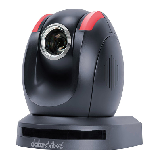
Page 6: Product Overview
1. Product Overview The PTC-150 HD/SD Video Camera is a PTZ camera that can be mounted on a wall, ceiling, floor, or a tabletop, and includes an IR remote control. The camera captures HD video at 1920 x 1080 resolution, and features wide dynamic range with backlight compensation. The camera features a motorized 22x optical zoom capability. -
Page 7: Location And Function Of Parts
3. Location and Function of Parts Front of Camera Lens Built-in 1/2.8” 2.0M Pixel CMOS HD color camera with white balance control, backlight compensation settings, automatic gain settings and etc. Tally LED Tally lamp lights up when tally signal has been transmitted to the tally signal box. - Page 8 Video signal output16-bit YCbCr 4:2:2 DVIP Communication Port Power Input DC 12V Input USB Port F/W Upgrade Only Bottom of Camera Tripod Screw Hole DIP Switch SW1 Camera ID setting for camera cascading Screw Hole Screw holes for ceiling bracket mounting...
-
Page 9: System Diagram
4. System Diagram... -
Page 10: Remote Control And On-Screen Menu
5. Remote Control and On-Screen Menu 5.1 Remote Control Functions Item Description Reset Press RESET button to return the camera lens to the front. Use the No. bottom & the group Group bottom to select the group scan. Press any of the No. buttons 1~8 and then press GROUP button. - Page 11 button. Return Camera Lens back to Front Press number 0 and then press PRESET button. Focus Setup Manually focus camera lens on a subject Press either (F) FAR button or (N) NEAR button to manually focus the camera lens onto the subject. Automatically focus camera lens on a subject Auto Focus Control Press A/ FOCUS button.
- Page 12 Direction Arrows Change camera direction Press arrow buttons to change the direction of the camera head. Stop Preset Point Auto Scan mode Press any of the DIRECTION buttons. Select Menu Option Press UP or DOWN button to select the menu option. Adjust P/T Speed Press UP or DOWN button to adjust the PAN/TILT Speed Enter Sub-Menu Option...
-
Page 13: On-Screen Menu
5.2 On-Screen Menu On-Screen Menu allows the user to change various camera settings such as shooting conditions and the system setup. Press [Menu] on the remote control to enter the on- screen menu as shown below. On-Screen MENU Camera Set (Normal) ... - Page 14 Effect Backlight Correction Day/Night Mode Shutter Escape Details of all options in the on-screen menu are listed in the table below. First Level Second Level Third Level Fourth Level Sub-Option Main Options Sub-Options Parameters Parameters Descriptions Name Display SW Camera Name LOWER LEFT Position UPPER RIGHT...
- Page 15 SMART ATW SMART1/2/3 MWB RED 0~128~255 COMPONENT MWB BLUE 0~128~255 COMPONENT AUTO FOCUS MODE MANUAL 0~8~15 AF SENSITIVITY Focus WHOLE SCREEN MIDDLE SIZE FOCUS AREA CENTER ONLY ESCAPE AUTO IRIS MODE MANUAL(EI OFF) MANUAL(EI ON) OUTDOOR-60 INDOOR-60 AUTO IRIS MODE Iris OUTDOOR-50 INDOOR-50...
- Page 16 COLOR HIGH AGC MODE LOW1 DAY (COLOR) LOW2 MID1 HIGH1 MANUAL DAY GAIN 0dB~42dB ESCAPE HIGH AGC MODE LOW1 NIGHT (B/W) LOW2 MID1 HIGH1 0dB~42dB MANUAL DAY GAIN ESCAPE D/N (AUTO) AGC AGC MODE...
- Page 17 HIGH LOW1 LOW2 MID1 HIGH1 ESCAPE DNR (AT AGC ON) 0~3~5 DNR LEVEL Escape Target Memory Group Escape BY MENU Selection Way BY SWITCH 1080i60 1080i50 720p60 Video Output 720p50 Video Mode 1080p30 1080p25 1080p60 1080p50...
- Page 18 16:9 CV Mode Escape ON/OFF PAN/TILT Reverse RS-422 DVIP Remote Source BY MENU CAMERA ID MODE BY SWITCH CAMERA ID Set RS-422 38400 RS-422 BAUD RATE 115200 Remote ESCAPE 38400 DVIP BAUD RATE 115200 Set DVIP ESCAPE IR GROUP ID CAM1~4 Set IR ESCAPE...
- Page 19 DEBUG IR OSD ON/OFF DEBUG CAM. OSD ON/OFF DEBUG RS-422 OSD ON/OFF DEBUG DVIP OSD ON/OFF DEBUG OSD DEBUG M CTL OSD ON/OFF DEBUG REG OSD ON/OFF DEBUG FRAME NO ON/OFF ESCAPE NORMAL PAN torque ADJ +1~+4 NORMAL Set Motor TILT torque ADJ +1~+4 ESCAPE...
- Page 20 UPPER LEFT LOWER LEFT POSITION ESCAPE Mirror AWB(AUTO) AWC(ONE PUSH) MWB (MANUAL) MODE 3200K (INDOOR) 6500K (OUTDOOR) 4200K (FLUO) White Balance SMART ATW SMART1~3 MWB RED 0~128~255 COMPONENT MWB BLUE 0~128~255 COMPONENT ESCAPE AUTO FOCUS MODE MANUAL 0~8~15 Focus AF SENSITIVITY WHOLE SCREEN FOCUS AREA MIDDLE SIZE...
- Page 21 CENTER ONLY ESCAPE AUTO IRIS MODE MANUAL(EI OFF) MANUAL(EI ON) OUTDOOR-60 INDOOR-60 AUTO IRIS MODE Iris OUTDOOR-50 INDOOR-50 AUTO IRIS LIMIT 0~64~255 MANUAL IRIS 0~128~255 STOP ESCAPE DNR(AT AGC ON) DNR LEVEL 0~3~5 ESCAPE AUTO SW DAY/NIGHT MODE COLOR DAY (COLOR) AGC AGC MODE HIGH LOW1...
- Page 22 LOW2 MID1 HIGH1 0dB~42dB MANUAL DAY GAIN ESCAPE HIGH AGC MODE LOW1 NIGHT (B/W) AGC LOW2 MID1 HIGH1 0dB~42dB MANUAL DAY GAIN ESCAPE HIGH D/N (AUTO) AGC AGC MODE LOW1 LOW2 MID1 HIGH1 ESCAPE...
- Page 23 DNR(AT AGC ON) 0~3~5 DNR LEVEL ESCAPE AUTO SMART 1 Gamma Mode SMART 2 SMART 3 FOG CORRECTION OFF/ON LEVEL Fog Correction 0~64~127 ESCAPE Vivid Effect 0~128~255 Pedestal Effect 0~128~255 Backlight Correction OFF/ON AUTO SW Day/Night Mode COLOR NORMAL SHUTTER SPEED Shutter 1/100~1/2000 ESCAPE...
-
Page 24: Instruction For Installation
6. Instruction for installation 6.1 Step 1 – DIP Switch Setting Set the IMAGE FLIP switch located on the rear panel to ON 6.2 Step 2 – One End of Retaining Wire Attach the retaining wire to the junction box mounted on the ceiling by screwing one end of the retaining wire into a screw hole in the junction box with a screw (not supplied) as shown in the diagram below. -
Page 25: Step 4 - Ceiling Bracket (A) And Camera
6.4 Step 4 – Ceiling Bracket (A) and Camera Screw ceiling bracket (A) into the bottom of the camera using three screws. Position the screws as shown in the diagram below Align the screw holes on the bottom of the camera with those in the ceiling bracket. -
Page 27: Step 5 - Mount Camera To Ceiling
6.5 Step 5 – Mount Camera to Ceiling... -
Page 28: Step 6 - Screw To Fix Camera
6.6 Step 6 – Screw to Fix Camera Fix the camera by screwing three screws into the corresponding screw holes as shown in the diagram below. -
Page 29: Step 7 - Cable Connection
6.7 Step 7 – Cable Connection Connect the cables to the connectors located on the rear of the camera. -
Page 30: Camera Dvip Setup
Set DIP Switch positions 1 and 4 to ON Plug in the power cord into the PTC-150 and connect it to a monitor via the HDMI interface. Open the main menu by pressing the menu button on the remote control and select option 4 “Remote Control”... - Page 31 Set the DVIP baud rate to to 115200 Connect your PC and the PTC-150 to an Ethernet router, which should automatically assign an IP to the PTC-150 On the PC, open the DVIP Configuration Tool by double clicking “DVIP_ConfigureTools.exe”. The DVIP Configuration Tool can be obtained from the Datavideo local distributors.
- Page 32 PTC-150. 11. After the network setting (True Static and DHCP) and the host name are configured, click the “Apply” button 12. The user will be prompted if the setup is successful. 13. Reboot the PTC-150 to apply the new settings...
-
Page 33: Camera Rs-422 Dip Switch Setting
8. Camera RS-422 DIP Switch Setting Setting VISCA ID (1,2,3) = (ON,OFF,OFF) VISCA-ID 1 VISCA-ID 2 (1,2,3) = (OFF,ON ,OFF) VISCA-ID 3 (1,2,3) = (ON ,ON ,OFF) VISCA-ID 4 (1,2,3) = (OFF,OFF,ON) VISCA-ID 5 (1,2,3) = (ON ,OFF,ON) VISCA-ID 6 (1,2,3) = (OFF,ON ,ON) VISCA-ID 7 (1,2,3) = (ON ,ON ,ON) -
Page 34: Irid Dip Switch
1280x720p50 (5,6,7) = (ON,ON,OFF) 1920x1080p30 (5,6,7) = (OFF,OFF,ON) 1920x1080p25 (5,6,7) = (ON,OFF,ON) 1920x1080p60 (5,6,7) = (OFF,ON,ON) 1920x1080p50 (5,6,7) = (ON,ON,ON) Setting Remote Source ON = video mode selected by DIP switch only (8) = (ON/OFF) OFF = video mode selected by menu 9. -
Page 35: Firmware Update
Copy three image files, p150mcpu.bin, P150FPGA.bin and p150mctl.bin, into the root directory of a USB hard drive (<16 GB) and insert it into the USB port of PTC-150 (You may also use USB extension cord). Open the operation menu of IR remote controller (select from CAM 1-4;... -
Page 36: Appearance
11. Appearance Unit: mm... -
Page 37: Specification
12. Specification Video Image Pickup Element 1/2.8 type progressive scan CMOS sensor Effective Picture Elements Approx. 2.0 Mega pixels Resolution HD / FHD / SD (CVBS only) HDMI & SDI: 1080/59.94p, 1080/59.94i, 1080/29.97p, 720/59.94p, 1080/50p, 1080/50i, 1080/25p, 720/50p Signal System CVBS: 480i/576i S/N Ratio 50dB... - Page 38 Focus Mode Auto / Manual / One-Push / STOP-AF Day & Night (IR) Auto / Color / BW Pan / Tilt / Zoom Pan/Tilt Range Pan: 270° , Tilt: +90° to -20° Manual: 1~150°/Sec Pan/Tilt Speed Swing: 1~150°/Sec Initialization Time 30 sec Preset 50 Position...
- Page 39 Remote Control RS-422 & DVIP by RJ-45 interface Remote Controller RMC-180 USB on rear side 1. Can upgrade by USB Dongle. F/W Update 2. When USB dongle plugs into the USB port, user can select OSD menu to start the F/W upgrade. 3.
-
Page 40: Service & Support
13. Service & Support...
Need help?
Do you have a question about the PTC-150 and is the answer not in the manual?
Questions and answers