Table of Contents
Advertisement
Quick Links
Advertisement
Table of Contents

Subscribe to Our Youtube Channel
Related Manuals for Datavideo PTC-120


Summary of Contents for Datavideo PTC-120
-
Page 2: Table Of Contents
5. Remote Control and On-Screen Menu ..........13 5.1 Remote Control Functions ..............13 5.2 Descriptions of Major Functions ............. 13 Switching between PTC-120 devices ............13 Saving current lens position data ............13 Clearing saved position data ..............14 Turning on backlight compensation function .......... - Page 3 Example 2 - Auto Focus Speed Adjustment ..........21 6. Instruction for installation ..............21 6.1 Preparation before Installation .............. 21 6.2 Installation of PTC-120 on the desk ............21 6.3 Installation of PTC-120 on the ceiling ............. 22 7. DIP Switch .................... 28 7.1 OUTPUT Switch ..................
- Page 4 Datavideo Technologies will try to give correct, complete and suitable information. However, Datavideo Technologies cannot exclude that some information in this manual, from time to time, may not be correct or may be incomplete. This manual may contain typing errors, omissions or incorrect information.
-
Page 5: Warnings And Precautions
AC adapter. If you are not sure of the type of power available, consult your Datavideo dealer or your local power company. Do not allow anything to rest on the power cord. Do not locate this unit where the power cord will be walked on, rolled over, or otherwise stressed. -
Page 6: Warranty
Hard Drives are only covered for the first 10,000 hours, or 1 year (whichever comes first). Any second year warranty claims must be made to your local Datavideo office or one of its authorized Distributors before the extended warranty expires. -
Page 7: Product Overview
1. Product Overview The Datavideo PTC-120 HD/SD Video Camera is a PTZ camera that can be mounted on a wall, ceiling, floor, or a tabletop, and comes with an IR remote control. The camera is equipped with • 1/2.8 inch image sensor •... -
Page 8: System Configuration
3. System Configuration The PTC-120 PTZ Color Video Camera can be set up in various system configurations. This section describes how PTC-120 can be connected as a standalone device as well as cascade connection of multiple cameras. 3.1 Single Camera Connection... -
Page 9: Sony Visca Compatible Controller
SONY VISCA Compatible Controller In addition to the supplied IR remote control, the PTC-120 camera can also be controlled remotely using a SONY VISCA compatible controller such as the Datavideo RMC-190 unit. This camera can be controlled over an RS-232C or RS-422 connection as shown in the diagrams below. -
Page 10: Multiple Cameras Cascade
3.2 Multiple Cameras Cascade The PTC-120 camera can also be used in an environment where multiple cameras are required. With RS-232 INPUT/OUTPUT ports, the user is allowed to cascade up to seven cameras, which are subsequently controlled by either a computer (Please download a utility program first from http://www.serialporttool.com/PTZ.htm... -
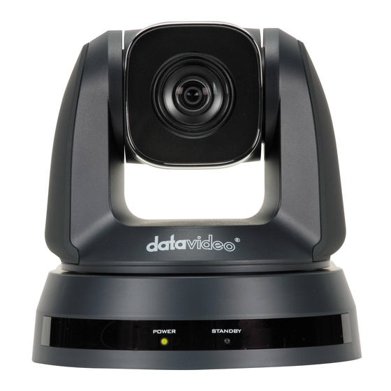
Page 11: Location And Function Of Parts
4. Location and Function of Parts Front of Camera Camera Lens 20x Optical Zoom; 12x Digital Zoom Power LED Indicator No Light: Power off Green: In use Flashing Green: Receiving signal from the remote control; the indicator flashes every 0.5 second Standby LED Indicator Orange: Standby mode No Light: Power on... - Page 12 RS-232C Output Connection of multiple cameras RS-232C Input VISCA Control (Section 13) RS-422 I/O Connection VISCA Control (Section 13) and Connection of multiple cameras Composite VIDEO Output Analog Video Transmission 3G-SDI Output Video Streaming Bottom of Camera System Switch (Section 9.4) DIP 1 selects RS-232C or RS-422 DIP 2 turns ON/OFF IR Signal Output Switch DIP 3 selects communication baud rate...
-
Page 13: Remote Control And On-Screen Menu
Zoom – Slow Press slow to zoom slowly 5.2 Descriptions of Major Functions Switching between PTC-120 devices Press [Camera 1 ~ 3] on the remote control to select the corresponding PTC-120 camera. • Camera 1 ~ 3 is selected with IR SELECT (Section 9.2). -
Page 14: Clearing Saved Position Data
Clearing saved position data Press [Reset + ID] on the remote control to clear the given position data. • ID shall be a digit [0 ~ 9]. • VISCA Command (Section 13) to clear the position data of [0~127] Turning on backlight compensation function Press [Back Light] on the remote control to turn on or turn off the back light compensation. -
Page 15: On-Screen Menu
5.3 On-Screen Menu On-Screen Menu allows the user to change various camera settings such as shooting conditions and the system setup. Press [Menu] on the remote control to enter the on- screen menu as shown below. On-Screen MENU • Exposure White Balance •... - Page 16 Details of all options in the on-screen menu are described in the table below. The bold underlined values are defaults. First Level Second Level Third Level Sub-Option Main Options Sub-Options Parameters Descriptions 1. Full Auto FULL AUTO: The exposure is adjusted automatically using 2.
- Page 17 1/3000 1/3000 1/2500 1/2500 1/2000 1/1750 1/1500 1/1250 1/1000 1/1000 1/725 1/600 1/500 1/425 1/350 1/300 1/250 1/215 1/180 1/150 1/120 1/120 1/100 1/100 1/90 1/75 1/60 1/50 1/30 1/25 1/15 1/12 ½ 0 dB 2 dB 4 dB 6 dB 8 dB 10 dB 12 dB...
- Page 18 1/180 1/150 1/120 1/120 1/100 1/100 1/90 1/75 1/60 1/50 1/30 1/25 1/15 1/12 8 dB 10 dB 12 dB 14 dB 16 dB 18 dB The maximum electric gain Gain Limit limit 20 dB 22 dB 24 dB 26 dB 28 dB 30 dB Wide Dynamic...
- Page 19 Auto 2D NR Set 2D noise reduction Set 3D dynamic noise 3D NR reduction Auto “Image Mode” option allows the user to apply different image settings, such as Mode1 saturation, hue, gamma, skin Mode2 tone and etc, to the image. Mode3 Modes 1-6 are fixed and Image Mode...
- Page 20 Turn on/off the angle limit PAN/TILT Limit ON/OFF setting PAN Right Limit 0~170 Limit the right angle PAN Left Limit -170~0 Limit the left angle Tilt UP Limit 0~90 Limit the upward angle PAN TILT ZOOM Tilt Down Limit -30~0 Limit the downward angle D-Zoom Limit x1~x12...
-
Page 21: Example 1 - Auto Focus Sensitivity Adjustment
6. Instruction for installation 6.1 Preparation before Installation To install PTC-120 by yourself, please follow the steps outlined below to ensure proper installation of the device. Make sure safety precautions are followed to avoid any accident. Ensure the safety of an installation environment. Do not install the device on a shaky •... -
Page 22: Installation Of Ptc-120 On The Ceiling
6.3 Installation of PTC-120 on the ceiling Preparation of the parts and equipment required for installation • Accessories of PTC-120 in the box (metal plates A, B and M3 screws) Screw for locking on ceiling mounted hangers ... - Page 23 Size Diagram • Metal plate B - Ceiling Side Metal plate B locking screw Metal plate B locking bolt...
- Page 24 M3 threaded hole M3 threaded hole M3 threaded hole Metal plate B - Ceiling Side Metal plate A - Machine Side Metal plate A - Locking Screw...
- Page 25 Metal plate A - Machine Side Bottom of Machine ...
-
Page 26: Precautions For Installation
• Precautions for Installation Before installation, please confirm the orientation of the device relative to the object to be captured. It is recommended that the device should be set at a distance of more than 1 meter away from the object to be captured. Please adjust for the optimized distance according to the magnification ratio of the lens. - Page 27 How to Remove • Remove the connecting wires from the camera To uninstall the camera from the ceiling, loosen the three screws that fix metal plates A and B and then push the device to the left to remove Finally remove the screws on the hanger and the device ...
-
Page 28: Dip Switch
7. DIP Switch PTC-120 offers the user four types of DIP Switch and prior to installation of the device, the user must first configure these DIP switch settings. Please turn off the machine before changing DIP switch setting. The four types of DIP switch are:... -
Page 29: Ir Select
7.2 IR SELECT IR Select assigns the camera an identification number when the user desires to operate multiple cameras using the Remote Control (Section 5.1). Setting 7.3 Camera Address Selector Camera Address Selector sets the camera address used in the cascade connection scenario. The user is allowed to cascade up to 7 cameras, which are controlled via either RS-232C interface or RS-422 interface. -
Page 30: Service Switch
DIP 1 of the System Switch is set to OFF. Camera Address Selector is set to zero. Setting Function Descriptions OFF (Default) Upgrade of Camera DSP FW/Camera Protocol FW/M3 Control FW PAN Motor Firmware Upgrade N.B. Please contact Datavideo’s technical team for firmware upgrade SOP. TILT Motor Firmware Upgrade... -
Page 31: Component Video Output
8. Component Video Output 8.1 DSub PIN Assignments PIN No. PIN Name Signals Red Video GREEN Green Video BLUE Blue Video ID2/RES Reserved Ground (HSync) RED_RTN Red return GREEN_RTN Green return BLUE_RTN Blue return KEY/PWR +5V DC Ground (VSync) ID0/RES Reserved ID1/SDA C Data... -
Page 32: Rs-232 Pin Assignments
Ground IR OUT IR Commander Signal (Output) N.C. No Connection 9.2 Wiring Diagrams With RS-232 interface, PTC-120 can be controlled using a home PC. The diagram below shows the connection in a PC-controlled scenario. Camera RS-232C PC RS-232C Terminal Terminal IR OUT N.C. -
Page 33: Rs-422 Pin Assignments
10. RS-422 PIN Assignments PTC-120 PTZ control function can be remotely controlled at any location via RS-422 interface 10.1 PIN Descriptions PIN No. Function RXD OUT- RXD OUT+ TXD OUT- TXD OUT+ RXD IN- RXD IN+ TXD IN- TXD IN+... -
Page 34: Physical Connection
10.2 Physical Connection Hold the two sides of RS-422 connector and pull out in the direction indicated by the arrow in the figure below Peel off a section of copper wire (AWG Nos.28 to18) and insert it into the connector hole;... -
Page 35: Wiring Diagrams
<Note> When RS-422 connection is being used; do not use RS-232C connection. 10.3 Wiring Diagrams To control PTC-120 with an external keyboard controller, establish RS-422 interface connections between PTC-120 and RMC-190 keyboard controller as shown below. RS-422 Interface on PTC-120... -
Page 37: Visca Commands
11. VISCA Commands Command Set Command Command Packet Comments AddressSet Broadcast 88 30 01 FF Address setting IF_Clear Broadcast 88 01 00 01 FF I/F Clear CommandCancel 8x 2p FF p: Socket No. (=1 or 2) 8x 01 04 00 02 FF CAM_Power Power ON/OFF Off (Standby) - Page 38 0x05:1080i-50 0x06:720p-60 0x07:720p-50 0x08:720p-30 0x09:720p-25 0x0A:1080p-5994 0x0B:1080i-5994 0x0C:1080p-2997 0x0D:720p-5994 0x0E:720p-2997 Auto 8x 01 04 35 00 FF Normal Auto Indoor 8x 01 04 35 01 FF Indoor Mode Outdoor 8x 01 04 35 02 FF Outdoor Mode One Push WB 8x 01 04 35 03 FF One Push WB mode 8x 01 04 35 04 FF...
- Page 39 1: Low 2: Typ 3: Max 4: Auto Gamma Setting CAM_Gamma 8x 01 04 5B 0p FF p: 0 to 3 8x 01 04 61 02 FF Mirror Image CAM_LR_Reverse ON/OFF 8x 01 04 61 03 FF 8x 01 04 62 02 FF CAM_Freeze Still Image ON/OFF 8x 01 04 62 03 FF...
- Page 40 Pan Position 8x 01 06 03 VV WW 0Y 0Y RelativePosition YYYY: 0000 to 0AD4 & F52C 0Y 0Y 0Z 0Z 0Z 0Z FF to FFFF (center 0000) Home 8x 01 06 04 FF Tilt Position ZZZZ: 0000 to 05C1 & Reset 8x 01 06 05 FF FE1B to FFFF (center 0000)
- Page 41 CAM_ImageModeBrig Set Brightness 8x 01 04 75 67 0p FF p: 0x0~0xE htness CAM_ImageModeCont Set Contrast 8x 01 04 75 68 0p FF p: 0x0~0xE rast CAM_Skin_Tone Select red level 8x 01 04 75 06 0p FF p: 0~4 p: 0 to 3 0: Off Black Level Black Level...
-
Page 42: Firmware Update
12. Firmware Update From time to time, Datavideo may release new firmware to either add new features or to fix reported bugs in the current RMC-260 firmware. Customers can update the firmware themselves if they wish or they can contact their local dealer or reseller for assistance should they prefer this method. -
Page 43: Connections
12.3 Connections PC: Connect the PTC-120 camera (RS-232 IN) to a PC running Windows Vista, XP, 7 or 8 via an RS- 232 Cable (Note: VC firmware cannot be updated using MAC system). RS232 cable Laptop: Connect the PTC-120 camera (RS-232 IN) to a laptop via an RS-232 Cable and an RS-232 to USB Cable as shown in the diagram below. -
Page 44: Dsp/Cm/M3 Control Firmware Update
12.6 DSP/CM/M3 Control Firmware Update Open firmware update tool VC Download Tool. Check the firmware that requires update (uncheck the box if not required). DSP *.bin File: VDGxxx • CM *.bin File: VCKxxx • • Motor *.bin File: VCHxxx Note: Please make sure the firmware file is correct as incorrect firmware file will cause the machine to malfunction. - Page 45 Select the corresponding COM PORT, set the Baud Rate to 9600 and then click the PROCESS button.
-
Page 46: Frequently-Asked Questions
13. Frequently-Asked Questions This section describes problems that you may encounter while using PTC-120. If you have questions, please refer to related sections and follow all the suggested solutions. If problem still exists, please contact your distributor or the service center. - Page 47 R/B Gain and L/R 1. R/B Gain is not an available function on PTC-120. Direction are not functional when 2. Commands of L/R Direction differ from PTC-120 thus controlling PTC-120 with L/R Direction is not functional. SONY’s RM-BR300 Keyboard Controller PTC-120 Cabling 1.
- Page 48 Control of PTC-120 The diagram below shows the user how they can connect using SONY’s RM- SONY’s RM-BR300 Keyboard Controller to the PTC-120 BR300 Keyboard camera via RS-232 interface. Controller on RS-232 interface Camera RS-232C SONY RM-BR300 Terminal IR OUT OPEN N.C.
-
Page 49: Specification
14. Specification Video Image Pickup Element 1/2.8 type CMOS Sensor Effective Picture Elements Approx. 2.0 Mega Pixels Resolution HD / FHD 1080p60/ 59.94/ 50/ 30/ 29.97/ 25 1080i60/ 59.94/ 50 Signal System 720p60/ 59.94/ 50/ 30/ 29.97/ 25 480i/ 576i (CVBS) S/N Ratio 50dB Electric Shutter... -
Page 50: Video Output
Video Output 3G-SDI x 1 DVI-D x 1 Video Output Component x 1 CVBS x 1 Video Format Output 1 V p-p / 75 Ohms. Control Protocol SONY VISCA Baud Rate 9600 / 38400 bps Remote Control RS-232 & RS-422 Remote Controller RMC-190 F/W Update... -
Page 51: Service & Support
15. SERVICE & SUPPORT...
Need help?
Do you have a question about the PTC-120 and is the answer not in the manual?
Questions and answers