Table of Contents
Advertisement
Quick Links
Advertisement
Table of Contents

Related Manuals for Datavideo PTC-150TW


Summary of Contents for Datavideo PTC-150TW
-
Page 2: Table Of Contents
Table of Contents Warnings and Precautions Warranty Standard Warranty Two Year Warranty Disposal 1. Product Overview 2. Features 3. Location and Function of Parts 4. System Diagram 5. Remote Control and On-Screen Menu 5.1 Remote Control Functions 5.2 On-Screen Menu 6. - Page 3 Datavideo Technologies will try to give correct, complete and suitable information. However, Datavideo Technologies cannot exclude that some information in this manual, from time to time, may not be correct or may be incomplete. This manual may contain typing errors, omissions or incorrect information.
-
Page 4: Warnings And Precautions
AC adapter. If you are not sure of the type of power available, consult your Datavideo dealer or your local power company. Do not allow anything to rest on the power cord. Do not locate this unit where the power cord will be walked on, rolled over, or otherwise stressed. -
Page 5: Warranty Standard Warranty
Certain parts with limited lifetime expectancy such as LCD Panels, DVD Drives, Hard Drives are only covered for the first 10,000 hours, or 1 year (whichever comes first). Any second year warranty claims must be made to your local Datavideo office or one of its authorized Distributors before the extended warranty expires. -
Page 6: Product Overview
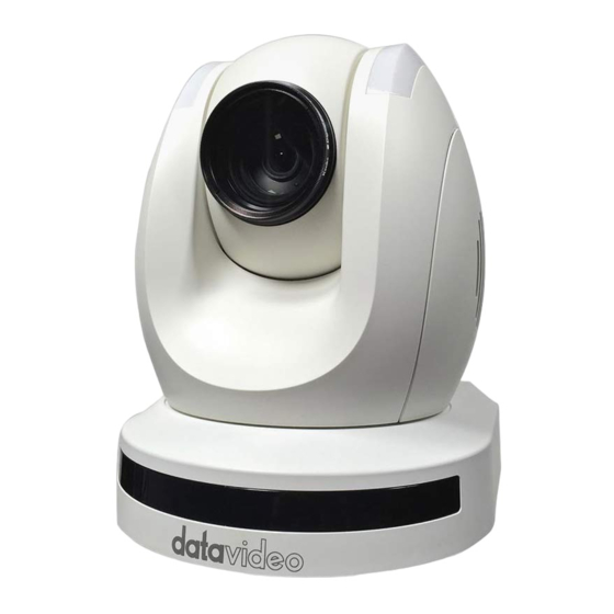
1. Product Overview The PTC-150 HD/SD Video Camera is a PTZ camera that can be mounted on a wall, ceiling, floor, or a tabletop, and includes an IR remote control. The camera captures HD video at 1920 x 1080 resolution, and features wide dynamic range with backlight compensation. The camera features a motorized 30x optical zoom capability. -
Page 7: Location And Function Of Parts
3. Location and Function of Parts Front of Camera Lens Built-in 1/2.8” 2.14M Pixel CMOS HD color camera with white balance control, backlight compensation settings, automatic gain settings and etc. Tally LED Tally lamp lights up when tally signal has been transmitted to the tally signal box. -
Page 8: System Diagram
4. System Diagram... -
Page 9: Remote Control And On-Screen Menu
5. Remote Control and On-Screen Menu 5.1 Remote Control Functions Item Description Reset Press RESET button to return the camera lens to the front. Use the No. bottom & the group bottom to select the group scan. Group Press any of the No. buttons 1~8 and then press GROUP button. - Page 10 Focus Setup Manually focus camera lens on a subject Press either (F) FAR button or (N) NEAR button to manually focus the camera lens onto the subject. Automatically focus camera lens on a subject Press A/ FOCUS button. Camera lens will be automatically focused Auto Focus Control on the subject such that it is positioned at the center of the screen.
- Page 11 Change camera direction Press arrow buttons to change the direction of the camera head Stop Preset Point Auto Scan mode Press any of the DIRECTION buttons Direction Arrows Select Menu Option Press UP or DOWN button to select the menu option Adjust P/T Speed Press UP or DOWN button to adjust the PAN/TILT Speed Enter Sub-Menu Option...
-
Page 12: On-Screen Menu
5.2 On-Screen Menu On-Screen Menu allows the user to change various camera settings such as shooting conditions and the system setup. Press [Menu] on the remote control to enter the on-screen menu as shown below. On-Screen MENU 1: Camera Set (Normal) 2: Memory 3: Video Output 4: Remote Control... - Page 13 Details of all options in the on-screen menu are listed in the table below. First Level Second Level Third Level Fourth Level Sub-Option Main Options Sub-Options Parameters Parameters Descriptions NAME DISPLAY SW ON/OFF 1. Camera Name LOWER LEFT POSITION UPPER RIGHT ESCAPE 2.
- Page 14 9 dB 12 dB 15 dB 18 dB 21 dB GAIN LIMIT 24 dB 27 dB 30 dB 33 dB 36 dB 39 dB ESCAPE DNR (AT AGC ON) DNR LEVEL ESCAPE ESCAPE 7. Escape 1-50 1. Preset Position ESCAPE PRESET NO.
- Page 15 GROUP – 2 GROUP – 3 GROUP – 4 GROUP – 5 GROUP – 6 GROUP – 7 GROUP – 8 ESCAPE 17. ESCAPE PRESET NO. 1~50 ITEM ON/OFF ON/OFF SPEED LIMIT 1~18 WAITING TIME 0~180 NEXT TIME RETURN GROUP – 1 GROUP –...
- Page 16 GROUP – 7 GROUP – 8 ESCAPE 17. ESCAPE PRESET NO. 1~50 ITEM ON/OFF ON/OFF SPEED LIMIT 1~18 WAITING TIME 0~180 NEXT TIME RETURN GROUP – 1 GROUP – 2 1-16 GROUP – 3 7. Group – 6 NEXT POSITION GROUP –...
- Page 17 17. ESCAPE 10. Escape BY MENU 1. Selection Way BY SWITCH 1080i60 1080i50 720p60 720p50 2. Video Mode 1080p30 3. Video 1080p25 Output 1080p60 1080p50 16:9 3. CV Mode 4. Pattern COLOR BAR 5. Escape 1. PAN/TILT Reverse RS-422, SW 2.
- Page 18 DEBUG M_CTL OSD ON/OFF DEBUG REG OSD ON/OFF DEBUG FRAME NO ON/OFF PWR ON CAM TEST ON/OFF ESCAPE PAN torque ADJ +1~+5 TILT torque ADJ +1~+5 +5.4 +4.5 +3.6 +2.7 +1.8 +0.9 PAN offset ADJ -0.9 -1.8 -2.7 -3.6 -4.5 -5.4 2.
- Page 19 LOWER RIGHT ESCAPE 2. Mirror AWB (AUTO) AWC (ONE PUSH) MWB (MANUAL) MODE 3200K (INDOOR) 6500K (OUTDOOR) 4200K (FLUO) 3. White SMART ATW Balance (Enabled in AWB (AUTO) SMART1~3 mode) MWB RED COMPONENT 0~128~255 MWB BLUE COMPONENT 0~128~255 ESCAPE AUTO FOCUS MODE MANUAL AF SENSITIVITY...
- Page 20 24 dB 27 dB 30 dB 33 dB 36 dB 39 dB ESCAPE DNR(AT AGC ON) DNR LEVEL ESCAPE FOG CORRECTION OFF/ON 7. Fog Correction ESCAPE 8. Aperture 0~15 9. Vivid Effect 0~14 10. Pedestal 0~14 Effect OFF/ON 11. Backlight (This option is enabled Correction after AGC is turned on)
-
Page 21: Instruction For Installation
6. Instruction for installation 6.1 Step 1 – DIP Switch Setting Set the Mirror option to H+V mode. 6.2 Step 2 – One End of Retaining Wire Attach the retaining wire to the junction box mounted on the ceiling by screwing one end of the retaining wire into a screw hole in the junction box with a screw (not supplied) as shown in the diagram below. -
Page 22: Step 4 - Ceiling Bracket (A) And Camera
6.4 Step 4 – Ceiling Bracket (A) and Camera Screw ceiling bracket (A) into the bottom of the camera using three screws. • Position the screws as shown in the diagram below • • Align the screw holes on the bottom of the camera with those in the ceiling bracket. -
Page 24: Step 5 - Mount Camera To Ceiling
6.5 Step 5 – Mount Camera to Ceiling... -
Page 25: Step 6 - Screw To Fix Camera
6.6 Step 6 – Screw to Fix Camera Fix the camera by screwing three screws into the corresponding screw holes as shown in the diagram below. 6.7 Step 7 – Cable Connection Connect the cables to the connectors located on the rear of the camera. -
Page 26: Dip Switch Settings
7. DIP Switch Settings 7.1 RS-422 Setting VISCA ID (1,2,3) = (ON,OFF,OFF) VISCA-ID 1 (1,2,3) = (OFF,ON ,OFF) VISCA-ID 2 (1,2,3) = (ON ,ON ,OFF) VISCA-ID 3 (1,2,3) = (OFF,OFF,ON) VISCA-ID 4 (1,2,3) = (ON ,OFF,ON) VISCA-ID 5 (1,2,3) = (OFF,ON ,ON) VISCA-ID 6 (1,2,3) = (ON ,ON ,ON) VISCA-ID 7... -
Page 27: Dvip Control Protocol
8. DVIP Control Protocol 8.1 DVIP Setup DVIP is a user interface that allows the user to control multiple PTC-150 cameras remotely. The DVIP setup procedure is outlined as follows: Locate the DIP switch at the bottom of the PTC-150 camera Set DIP Switch positions 1 and 4 to ON Plug in the power cord into the PTC-150 and connect it to a monitor via the HDMI interface. - Page 28 IP to the PTC-150 On the PC, open the DVIP Configuration Tool by double clicking “DVIP_ConfigureTools.exe”. The DVIP Configuration Tool can be obtained from the Datavideo local distributors. After the DVIP Configuration Tool is opened, select your network interface card as the...
- Page 29 10. On the DVIP Device List, you will then be able to see the Device Name, MAC address and IP address of the connected PTC-150. 11. After the network setting (True Static and DHCP) and the host name are configured, click the “Apply”...
-
Page 30: Dvip Control Operation Guide
8.2 DVIP Control Operation Guide 8.2.1 Physical Layer Control Interface: Ethernet • • Communication Speed: 10/100Mbps • Control Protocol: TCP/IP 8.2.2 General Connection Information By default, the DVIP is configured to operate in DHCP mode. User is allowed to re- •... - Page 31 Command Return from DVIP device Length Descriptions 1 Byte Data Length High Byte 1 Byte Data Length Low Byte 1 Byte 0x80 1 Byte 0x00 1 Byte DHCP; 0: Disable; 1: Enable 16 Bytes DHCP Host name (15 bytes max) + Null (0x00) terminated 6 Bytes MAC Address 4 Bytes...
- Page 32 Broadcast Command List – Set DHCP Mode Command Issue to DVIP device Set DHCP Mode Command 0x02 Parameter 1 DVIP MAC address [0] Parameter 2 DVIP MAC address [1] Parameter 3 DVIP MAC address [2] Parameter 4 DVIP MAC address [3] Parameter 5 DVIP MAC address [4] Parameter 6...
- Page 33 Parameter 14 0x44 Parameter 15 0x52 Parameter 16 IP_Address [0] Parameter 17 IP_Address [1] Parameter 18 IP_Address [2] Parameter 19 IP_Address [3] Parameter 20 Gateway [0] Parameter 21 Gateway [1] Parameter 22 Gateway [2] Parameter 23 Gateway [3] Command Return from DVIP device Length Descriptions 1 Byte...
- Page 34 Parameter 2 DVIP MAC address [1] Parameter 3 DVIP MAC address [2] Parameter 4 DVIP MAC address [3] Parameter 5 DVIP MAC address [4] Parameter 6 DVIP MAC address [5] Parameter 7 0x47 Parameter 8 0x45 Parameter 9 0x54 Parameter 10 0x5F Parameter 11 0x4D...
- Page 35 Parameter 6 0x45 Parameter 7 0x51 Command Return from DVIP device Length Descriptions 1 Byte Data Length High Byte 1 Byte Data Length Low Byte 1 Byte 0x80 1 Byte 0x00 1 Byte DHCP; 0: Disable; 1: Enable 16 Bytes DHCP Host name (15 bytes max) + Null (0x00) terminated 6 Bytes MAC Address...
- Page 36 Parameter 4 0x5F Parameter 5 0x44 Parameter 6 0x48 Parameter 7 0x43 Parameter 8 0x50 Parameter 9 0x4D Parameter 10 0x4F Parameter 11 0x44 Parameter 12 0x45 Parameter 13 0x00: Disable; 0x01: Enable Command Return from DVIP device Length Descriptions 1 Byte 0x00 (Data Length High Byte) 1 Byte...
- Page 37 UDP Command List – Reset to Factory Default Command Issue to DVIP device Reset to Factory Default Command 0x04 Parameter 1 0x52 Parameter 2 0x45 Parameter 3 0x53 Parameter 4 0x45 Parameter 5 0x54 Command Return from DVIP device Length Descriptions 1 Byte 0x00 (Data Length High Byte)
- Page 38 UDP Command List – Set Netmask Command Issue to DVIP device Set Netmask Command 0x0B Parameter 1 0x53 Parameter 2 0x45 Parameter 3 0x54 Parameter 4 0x5F Parameter 5 0x4E Parameter 6 0x45 Parameter 7 0x54 Parameter 8 0x4D Parameter 9 0x41 Parameter 10 0x53...
- Page 39 Command Return from DVIP device Length Descriptions 1 Byte 0x00 (Data Length High Byte) 1 Byte 0x05 (Data Length Low Byte) 1 Byte 0x81 1 Byte 0x0C 1 Byte 0x06 (ACK) or 0x15 (NACK) UDP Command List – Set Primary DNS Address Command Issue to DVIP device Set Gateway Address Command...
- Page 40 Parameter 10 0x53 Parameter 11 Secondary_DNS_IP [0] Parameter 12 Secondary _DNS_IP [1] Parameter 13 Secondary _DNS_IP [2] Parameter 14 Secondary _DNS_IP [3] Command Return from DVIP device Length Descriptions 1 Byte 0x00 (Data Length High Byte) 1 Byte 0x05 (Data Length Low Byte) 1 Byte 0x81 1 Byte...
-
Page 41: Rs-422 Control Protocol
9. RS-422 Control Protocol 9.1 RS-422 PIN Descriptions Camera Controller 9.2 RS-422 Control Operation Guide 9.2.1 Overview of VISCA In VISCA, the side outputting commands, for example, a computer is called the controller, while the side receiving the commands, such as a PTC-150, is called the peripheral device. The PTC-150 serves as a peripheral device in VISCA. -
Page 42: Visca Communication Specifications
When the address of the controller is fixed at 0 The addresses of the peripheral devices are 1, 2, 3… in order, starting from the one nearest the controller. The address of the peripheral device is set by sending address commands during the initialization of the network. - Page 43 Fig. 2 Packet structure Note Fig. 2 shows the packet structure, while Fig. 3 shows the actual waveform. Data flow will take place with the LSB first. Fig. 3 Actual waveform for 1 byte 9.2.2.2 Timing Chart As VISCA Command processing can only be carried out one time in a Vertical cycle, it takes the maximum 1V cycle time for an ACK/Completion to be returned.
- Page 44 From this point, if 2 or more commands in a row are to be sent, wait for the first command (for normal commands, an ACK or an error message, for query commands, an Inquiry Packet) to be carried out before sending the next one. 9.2.2.3 Command and inquiry Command •...
-
Page 45: Visca Device Setting Command
9.2.2.5 Socket number When command messages are sent to the PTC-150, it is normal to send the next command message after waiting for the completion message or error message to return. As the completion message or error message also has a socket number, it indicates which command has ended. -
Page 46: Visca Camera-Issued Messages
81 09 05 38 FF 90 60 02 FF Accepted an incompatible (Example) (Syntax Error) command. Address Set 88 30 01 FF 88 30 02 FF Returned the device address to +1.* IF_Clear 88 01 00 01 FF 88 01 00 01 FF Returned the same (Broadcast) command. -
Page 47: Ptc-150 Commands
9.2.6 PTC-150 Commands 9.2.6.1 PTC-150 Command List Command Set Command Command Packet Comments AddressSet Broadcast 88 30 01 FF Address Set IF_Clear Broadcast 88 01 00 01 FF I/F Clear CAM_Power 8x 01 04 00 02 FF Power On/Off 8x 01 04 00 03 FF CAM_ZOOM Stop 8x 01 04 07 00 FF... - Page 48 mode Shutter Priority 8x 01 04 39 0A FF Shutter priority automatic exposure mode Iris Priority 8x 01 04 39 0B FF Iris priority automatic exposure mode Bright 8x 01 04 39 0D FF Bright mode (Manual) CAM_Shutter Reset 8x 01 04 0A 00 FF Default Shutter setting 8x 01 04 0A 02 FF...
- Page 49 Home 8x 01 06 04 FF Reset 8x 01 06 05 FF CAM_ImgFlip 8x 01 04 66 02 FF 8x 01 04 66 03 FF Cam_PanReverse 8x 01 7E 01 06 00 01 FF 8x 01 7E 01 06 00 00 FF Cam_TiltReverse 8x 01 7E 01 09 00 01 FF 8x 01 7E 01 09 00 00 FF...
- Page 50 rstu: ROM version vw: Socket Number (02) CAM_ImgFlipInq 8x 09 04 66 FF y0 50 02 FF y0 50 03 FF CAM_PanReverseInq 8x 09 7E 01 06 y0 50 01 FF y0 50 00 FF CAM_TiltReverseInq 8x 09 7E 01 09 y0 50 01 FF y0 50 00 FF PanTilt_Status...
-
Page 51: Firmware Update
10. Firmware Update Copy three image files, p150mcpu.bin, P150FPGA.bin and p150mctl.bin, into the root directory of a USB hard drive (<16 GB) and insert it into the USB port of PTC-150 (You may also use USB extension cord). Open the operation menu of IR remote controller (select from CAM 1-4; default is CAM1) Main Menu =>... -
Page 52: Dimensions
11. Dimensions Unit: mm... -
Page 53: Specification
12. Specification Video Image Pickup Element 1/2.8” type progressive scan CMOS sensor Effective Picture Elements Approx. 2.14 Mega pixels Resolution HD / FHD / SD (CVBS only) HDMI & SDI: 1080/59.94p, 1080/59.94i, 1080/29.97p, 720/59.94p, 1080/50p, 1080/50i, 1080/25p, 720/50p Signal System CVBS: 480i, 576i S/N Ratio 50 dB... - Page 54 Lens Lens Type 30x Optical Zoom F=4.3 mm (WIDE) to 129 mm (TELE) Focal Length F1.6 to F4.7 Angle of View (Horizontal) Approx. 63.7 degrees (WIDE END) / 2.3 degrees (TELE END) Video Output HDMI (V1.3) x 1 Video Output HD-SD-SDI x 1 CVBS x 1 Video Format Output...
-
Page 55: Service & Support
13. Service & Support...
Need help?
Do you have a question about the PTC-150TW and is the answer not in the manual?
Questions and answers