Table of Contents
Advertisement
Advertisement
Table of Contents

Related Manuals for Datavideo PTC-140


Summary of Contents for Datavideo PTC-140
- Page 1 PTC-140...
-
Page 2: Table Of Contents
Table of Contents FCC COMPLIANCE STATEMENT ................4 WARNINGS AND PRECAUTIONS ................. 4 WARRANTY ......................5 ..................5 TANDARD ARRANTY ..................6 HREE ARRANTY DISPOSAL ......................6 PRODUCT OVERVIEW ................. 8 ......................8 EATURES LOCATION AND FUNCTION OF PARTS ............9 BASIC SETUP .................... - Page 3 Further advice on the content of this manual or on the product can be obtained by contacting your local Datavideo Office or...
-
Page 4: Fcc Compliance Statement
7. This product should only be operated from the type of power source indicated on the marking label of the AC adapter. If you are not sure of the type of power available, consult your Datavideo dealer or your local power company. -
Page 5: Warranty
Warranty Standard Warranty Datavideo equipment are guaranteed against any manufacturing defects for one year from the date of purchase. The original purchase invoice or other documentary evidence should be supplied at the time of any request for repair under warranty. -
Page 6: Three Year Warranty
PCIe Card are covered for 1 year. The three-year warranty must be registered on Datavideo's official website or with your local Datavideo office or one of its authorized distributors within 30 days of purchase. Disposal For EU Customers only - WEEE Marking... - Page 7 the recycling of waste electrical and electronic equipment. The separate collection and recycling of your waste equipment at the time of disposal will help to conserve natural resources and ensure that it is recycled in a manner that protects human health and the environment. For more information about where you can drop off your waste equipment for recycling, please contact your local city office, your household waste disposal service or the shop where you purchased the product.
-
Page 8: Product Overview
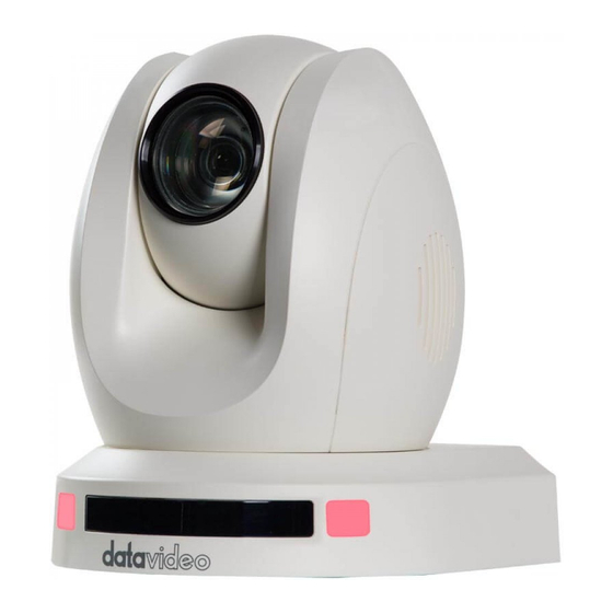
Product Overview The PTC-140 is a low-cost SDI/HDMI PTZ camera featuring 20x optical zoom and 10x digital zoom. The PTC-140 is also an IP camera supporting H.264 /H.265 video compression and dual stream outputs. Features 1/2.8 inch CMOS sensor. Resolution is up to 1920x1080 with frame rate up to 60fps. -
Page 9: Location And Function Of Parts
Location and Function of Parts Front of Camera Lens Built-in 1/2.8” 2.07M Pixel CMOS HD color camera with white balance control, backlight compensation, automatic gain and etc. Tally LED Tally lamp will be turned ON upon receiving the ON signal. Sensor for Remote Control Remote control IR receiver... - Page 10 Rear of Camera Power Input DC in socket connects the supplied 12V PSU. The connection can be secured by screwing the outer fastening ring of the DC In plug to the socket. LAN Port This port allows you to establish network connection with the camera. Connect an Ethernet cable from this port to the LAN port of a PC in order to monitor the camera video from the web user interface.
- Page 11 OSD menu, then go to Setup RS-485/422 in which you will be allowed to select the appropriate protocol. RS-232 Interface (RJ-45) The RS-232 interface connects PTC-140 to a remote controller or PC for control purpose. Use an Ethernet cable to connect external RS-232 controllers. See “Section 8 Remote Control Port...
- Page 12 Bottom of Camera Tripod Screw Hole allows the user to mount the camera on the tripod. Screw Hole Screw holes for ceiling bracket mounting. For Safety Rope Ties safety rope for fixing the camera to the ceiling.
-
Page 13: Basic Setup
Ethernet Port Follow the instructions below to view your video on the web user interface. 1. Connect the PTC-140 to the PC/Notebook using an Ethernet cable. 2. On your PC/Notebook, open the web browser and enter camera’s default IP address into the address bar (default static IP address is 192.168.5.163). -
Page 14: Hdmi Video Output
4. Click into the preview window on which the video will be displayed. HDMI Video Output Connect the HDMI OUT to an external connected monitor using an HDMI cable. 3G-SDI Video Output Connect the SDI OUT to an external connected monitor using an SDI cable. -
Page 15: Remote Control And On-Screen Menu
Remote Control and On-Screen Menu This chapter provides an overview of remote control functions and OSD menu. 4.1 Remote Control Functions... - Page 16 Function Keys Descriptions Standby Key The standby button turns ON/OFF the camera. Standby Key To reboot the camera, press the standby button for 3 seconds. After device initialization is complete, the camera head will automatically return to HOME position. Camera Select Keys To select a camera in a multi-camera environment using camera select keys (CAM1 –...
- Page 17 Function Keys Descriptions The asterisk and pound keys form various combinations with other keys to access certain functions directly. The shortcuts are listed as follows: 1. 【#】+【#】+【#】: Clear all presets 2. 【*】+【#】+【6】: Restore factory defaults 3. 【*】+【#】+【9】: Image flip along horizontal axis 4.
- Page 18 Function Keys Descriptions Manual Focus Manual Mode Pressing this key enables manual mode allowing you to adjust the camera’s focus and zoom by pressing Focus+/- and Zoom+/- keys. Focus Focus +/- Press and hold Focus+ or Focus- to adjust the focus accordingly and release as soon as the desired focus is reached.
- Page 19 Function Keys Descriptions Direction Arrow Keys Direction Arrows Press the arrow keys to move the camera head up, down, left and right. 11-13 Home Key Press Home to return the camera head to the center. Note: In the OSD menu, press Home to enter the selected option item and MENU to exit.
-
Page 20: On-Screen Menu
4.2 On-Screen Menu On-Screen Menu allows the user to modify various camera settings. Press [MENU] on the remote control to open the on-screen menu as shown below. On-Screen MENU Language Setup Camera P/T/Z Video Format Version Restore Default Escape [↑↓] Select [←... - Page 21 Details of all options in the on-screen menu are listed in the table below. Main Menu Sub Menu Options Sub-options English Language Simplified Chinese Auto VISCA Protocol PELCOO-D PELCCO-P VISCCA Address VISCA Address Fix ON/OFF PELCO-P Address 1-255 PELCO-D Address 1-255 Setup 2400...
- Page 22 Main Menu Sub Menu Options Sub-options Flicker 50Hz 60Hz Gain Limit 0~15 Closed Auto 3000K 3500K 4000K 4500K 5000K WB Mode 5500K 6000K 6500K 7000K Manual Color Onepush RG Tuning...
- Page 23 Main Menu Sub Menu Options Sub-options BG Tuning Saturation 100% 110% 120%...
- Page 24 Main Menu Sub Menu Options Sub-options 130% 140% 150% 160% 170% 180% 190% 200% High AWB Sensitivity Middle Image Brightness...
- Page 25 Main Menu Sub Menu Options Sub-options Contrast Sharpness Flip-H Flip-V Color B & W Mode Black & White...
- Page 26 Main Menu Sub Menu Options Sub-options Default 0.45 Gamma 0.50 0.55 0.63 Closed Auto Focus Mode Manual Onepush Center Focus AF-Zone Bottom High AF-Sensitivity Middle Auto NR-2D Noise Reduction NR-3D...
- Page 27 Main Menu Sub Menu Options Sub-options Dynamic Hot Pixel Default Normal Style Clarity Bright Soft Zoom by Speed Zoom Speed P/T/Z Standard Acc Curve Slow Fast Fast Preset Speed Slow Middle Positive Joystick Pan Dir Negative Positive Joystick Tilt Dir Negative 1080P60 1080P50...
- Page 28 Main Menu Sub Menu Options Sub-options 1080P25 720P60 720P50 1080P59.94 1080I59.94 1080P29.97 720P59.94 MCU Version Version Camera Version AF version Restore Default Restore Default (Yes/No)
-
Page 29: Installation Instructions
PM3*5 screw x 6 Ceiling bracket (upper and lower plates) x 1 PTC-140 camera x 1 Ceiling Bracket (Upper and Lower Plates Step 1: The Ceiling Bracket Separate the ceiling bracket into two parts (upper and lower plates) as depicted in the diagram below. - Page 30 Using four PA4*30 self-tapping screws, affix the bracket’s upper plate to the ceiling. Upper Plate of Ceiling Bracket Step 3: Affix the bracket’s lower plate to the bottom of PTC-140 As depicted in the diagram below, use three PM3*5 screws to affix the bracket’s lower plate to the bottom of PTC-140.
- Page 31 Lower Plate of Ceiling Bracket Step 4: Mount the PTC-140 Camera to the ceiling Now push the PTC-140 camera into the bracket’s upper plate in the direction as indicated by the arrow in the diagram below. Make sure the two plates click into place.
- Page 32 Step 5: Final...
-
Page 33: Network Connection
Network Connection The Ethernet port on the back panel of your PTC-140 allows you to connect to camera from the PC/Laptop with Static or dynamic IP addresses. To access and modify these network settings, you will need to login to the camera’s web interface. -
Page 34: Dhcp Mode
IP. In this chapter, we will show you how to enable DHCP and Static IP modes on PTC-140 in two separate sections. Note: To log out of the web interface, simply click “Logout” at the top right corner of the page. - Page 35 In order to enable the camera’s DHCP mode, simply check the DHCP checkbox to allow the router to dynamically assign an IP address to PTC-140. Click “Save” button to save the new settings then reboot PTC-140.
-
Page 36: Static Ip
6.2 Static IP A static IP address is a fixed address manually assigned to PTC-140. First uncheck the DHCP checkbox then enter an IP address for the camera, the subnet mask and the gateway IP. Note: Never assign an address that ends in .0 or .255 as these addresses are typically reserved for network protocols. - Page 37 Step 1: Open the DVIP Network Configuration Tool and on the toolbar, click “Network” then “Network Card.” Step 2: On the pop-up dialogue box, select your network interface from the drop- down menu.
- Page 38 Step 3: Click the “Search” button. Step 4: After the entire network has been scanned, you will see a list of available devices displayed on the left as shown in the diagram below. Click the device name to view its network settings which can then be modified if necessary.
-
Page 39: Web User Interface
Web User Interface The web based user interface allows you to set and control your PTC-140 devices. Preview In preview, you will be able to see the camera image in real time as shown in the diagram below. Click on the preview window once to view in full screen mode and click again to exit. - Page 40 Controls Descriptions PTZ Control Buttons Click the arrow buttons to move the camera head to corresponding directions. To return to Home position, click PTZ Speed Slider The PTZ speed slider adjusts the P/T speed, ranging from 0 (slowest) to 100 (fastest).
-
Page 41: Preset
Preset The presets allow you to save multiple PTZ settings to the camera. See function descriptions in the table below. Functions Descriptions Preset Drop-Down Menu Select a preset number from the drop- down menu. Note: There are 255 presets ranging from 0 –... -
Page 42: Configuration
Configuration In Configuration, you will be able to configure the camera’s audio, video, network and system settings which will be described further in the next few sections. Audio Configure Audio Configure allows you to configure the input audio source. See the table below for descriptions of each item. Items Descriptions Enable... - Page 43 Items Descriptions Sample Rate Select a sample rate for your input audio source. The higher the sample rate, the better the audio quality. Sample Bits Select the sample bits for your input audio source. The default is 16. Bit Rate Select a bit rate for your input audio source.
-
Page 44: Video Configure
Video Configure Video Configure allows you to configure the input video source. Video Encode In Video Encode, you will be able to configure the video quality for main and sub streams. See the diagram below for various video settings. See the table below for descriptions of each item. Items Descriptions Compressed Format... - Page 45 Image Size Select an appropriate image size from the drop-down menu. 1920 x 1080 1280 x 720 640 x 480 Rate Control CBR encoding does not optimize media files for quality but will save you storage space. VBR takes longer to encode but produces the most favorable results as the quality of the media file is superior.
- Page 46 I Frame Interval A shorter I Frame Interval results higher quality video but consumes more network bandwidth. On the other hand if longer I Frame Interval is set, less bandwidth will be required but it will result in lower video quality. I frame interval is 75 by default.
- Page 47 See the table below for descriptions of each item. Items Descriptions Enable Check this checkbox to enable RTMP stream. Protocol Type By default the protocol type is RTMP. Host Address This is the RTMP Server URL provided by the video streaming providers. An example of the RTMP Server URL is provided.
- Page 48 3. On the left column, locate and click “Stream now.” 4. On the right, scroll down to the bottom where you will be able to find Server URL and Stream name/key. 5. Open the PTC-140’s web UI and click “Video Configure” “Stream Publish.”...
- Page 49 6. Enter the Server URL and Stream Name/Key into Host Address and Stream Name respectively. 7. Check the Enable checkbox to enable RTMP stream. 8. Click the Save button to save the RTMP settings and start broadcasting your camera video on Youtube. Stream to Facebook 1.
- Page 50 2. Check “Use a persistent stream key” then copy and paste “Server URL” and “Persistent Stream Key” into “Host Address” and “Stream Name” as shown on the PTC-140’s web UI respectively.
- Page 51 3. Check the Enable checkbox to enable RTMP stream. 4. Click the Save button to save the RTMP settings. On Facebook Live, choose where you want to post your live broadcast then click “Go Live” button to start broadcasting your camera video. RTP Multicast The RTP Multicast allows you to view camera video on certain video players such as VLC media player from a remote location.
- Page 52 You can also choose to stream over TS protocol. Follow the steps outlined below to view the camera video on VLC media player over TS protocol. 1. On RTP Multicast page of the PTC-140’s web interface, select “TS” from the Protocol Type drop-down menu.
- Page 53 2. Open VLC media player, click “Media” “Open Network Stream” then enter udp://@224.1.2.3:4000 to view the main stream and udp://@224.1.2.3:4002 to view the sub stream. 3. Click the “Play” button to start viewing the video stream. Video Parameters This sets the camera focus, exposure, color balance, image settings, noise reduction and picture styles.
- Page 54 Exposure In Exposure, you are allowed to set Exposure Mode, Exposure Value (EV), Backlight Compensation (BLC), Anti-Flicker, Gain Limit and Dynamic Range Compression (DRC). Mode: Available focus modes are Auto, Manual, SAE (Shutter Automatic Exposure), AAE (Aperture Automatic Exposure) and Bright. Auto –...
- Page 55 Aperture Automatic Exposure – The camera will measure light and automatically set the shutter speed based on your desired iris opening (aperture). EV: EV is exposure value. By turning it ON, an EV slider will appear for adjusting the exposure value. ...
- Page 56 WB Mode: Select white balance mode from the options listed below. Auto 3000K 3500K 4000K 4500K 5000K 5500K 6000K 6500K 7000K Manual One Push RG Tuning: This fine tunes the red gain from -10 to 10 but effective only in AUTO mode.
- Page 57 BG Tuning: This fine tunes the blue gain from -10 to 10 but effective only in AUTO mode. Saturation: 60% to 200%. Note: The higher the saturation, the more vivid the colors will be. Hue: Chroma adjustment from 0 to 14. ...
- Page 58 Bright: Brightness level adjustment from 0 to 14. Contrast: Contrast adjustment from 0 to 14. Sharpness: Sharpness adjustment from 0 to 15. Gamma: Selects a gamma value from the following Default 0.45 0.50 0.55 0.63 DCI: To enable DCI, simply select a value from 1 to 8;...
- Page 59 NR-2D: 2D noise reduction is ideal for scenes with movement. 1 – 7 Auto NR-3D: 3D noise reduction is ideal for static fields of view. 1 – 7 Note: By using both 2D and 3D noise reduction together, you can effectively enhance both moving and static imagery, which is ideal for most live broadcast environments.
- Page 60 Style In Style, you will be able to select the picture style of your preference. The available styles are: Default Normal Clarity Bright Soft Note: Each time after you modify the camera parameters, please click the Refresh button to apply the new settings. Video OSD In Video OSD, you will be allowed to show video time and title on the screen.
- Page 61 Enable Video Time and Title on Screen Simply check the checkbox then click the Save button to display video time and title on the screen. Set Font Color of Time and Title You can also select a display color for your time and title. Available color options include: ...
- Page 62 Adjust Time and Title Positions On the OSD Offset tile, you will be allowed to adjust positions of the Time and Title displayed on the screen. First select Time or Title then click the arrow buttons to move it to the desired position. Note: After you’ve configured the video time and title, click the Save button to apply the new settings.
- Page 63 Video OUT The Video Out allows users to select the desired video output resolution from the drop-down menu. Supported output resolutions include: 1080P60 1080P50 1080P30 1080P25 1080I60 1080I50 720P60 720P50 1080P59.94 ...
-
Page 64: Network Configure
Network Configure Network Configure allows you to configure the network functions of your camera. Network Port In Network Port, you should be able to find a list of default port numbers for different data communication protocols. Please note that these port numbers may vary according to your network environment. - Page 65 In DNS, Enter the DNS information which is 8.8.8.8 by default.
-
Page 66: System Configure
System Configure System Configure allows you to configure your camera system. System Attribute In System Attribute, you are allowed to edit your camera name and select the Web UI language. Available languages are Traditional Chinese, Simplified Chinese and English. System Time In System Time, you are allowed to set the Date Format, Time Zone, Hour Type and NTP. - Page 67 System User In System User, you are allowed to edit the login credentials for Admin, User 1 and User 2. Note: Click the Save button to save the new login credentials.
- Page 68 Update This is where you will be able to view current firmware information. See Firmware Update for detailed firmware upgrade instructions.
- Page 69 Default In Default, click “Restore factory defaults” to reset the device to factory defaults. Reboot Click “Reboot” to reboot the device.
-
Page 70: Remote Control Port Pinouts
PC or any keyboard controllers to the RS-232 or RS-422/RS-485 remote port to control PTC-140. Use an Ethernet cable to connect the external RS-232 or RS- 422/RS-485 controller to PTC-140. You can make your own cable using the pinout information provided in this chapter. - Page 71 The RS-422/RS-485 pinouts are described below. RJ-45 Connector Camera’s RS-422/485 Port White/Orange Orange White/Green Blue White/Blue Green White/Brown Brown...
-
Page 72: Firmware Update
Firmware Update Datavideo usually releases new firmware containing new features or reported bug fixes from time to time. Customers can either download the firmware as they wish or contact their local dealer or reseller for assistance. This section outlines the firmware upgrade process which should take approximately few minutes to complete. -
Page 73: Frequently-Asked Questions
10. Frequently-Asked Questions This section describes problems that you may encounter while using PTC-140. If you have any questions, please refer to related sections and follow all suggested solutions. If problem still exists, please contact your distributor or the service center. -
Page 74: Dimensions
11. Dimensions Unit: mm... -
Page 75: Specifications
12. Specifications Video Image Sensor 1/2.8 inch high quality HD CMOS sensor Zoom Ratio 20x Optical Zoom, 10x Digital Zoom f=5.2 (wide) to 98 (tele) mm Focal Length F1.6 to F3.5 Effective Pixels 2.07 Mega pixels (Approx.) 1080p60/59.94/50/30/29.97/25 Video Format 1080i60/59.94/50 720p60/50/59.94 Field of View... - Page 76 Input / Output Interface Video Output SDI x 1, HDMI x 1 Video Compression H.264, H.265, Dual stream output Format VISCA/Pelco-D/Pelco-P; Baud Rate: 115200 / 38400 / Protocol 9600 / 4800 / 2400 bps DVIP Audio Input 3.5mm mic in/line in (not available) Audio Compression AAC/MP3/PCM Audio compression Audio Output...
-
Page 77: Service & Support
Notes... - Page 78 Datavideo Technologies Co., Ltd. All rights reserved 2020 Apr-29.2020 Ver:E3...
Need help?
Do you have a question about the PTC-140 and is the answer not in the manual?
Questions and answers