
Related Manuals for Datavideo PTC-150TL


Summary of Contents for Datavideo PTC-150TL
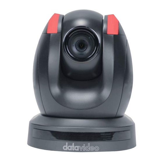
- Page 1 HD/SD-SDI HDBaseT PTZ CAMERA PTC-150T/ PTC-150TW Instruction Manual w w w . d a t a v i d e o . c o m...
-
Page 2: Table Of Contents
Table of Contents FCC COMPLIANCE STATEMENT ..............4 WARNINGS AND PRECAUTIONS ..............4 WARRANTY ....................6 ..................6 TANDARD ARRANTY ..................6 HREE ARRANTY DISPOSAL ...................... 7 1. PRODUCT OVERVIEW ................8 2. FEATURES ....................8 3. LOCATION AND FUNCTION OF PARTS ............9 4. - Page 3 Disclaimer of Product and Services The information offered in this instruction manual is intended as a guide only. At all times, Datavideo Technologies will try to give correct, complete and suitable information. However, Datavideo Technologies cannot exclude that some information in this manual, from time to time, may not be correct or may be incomplete.
-
Page 4: Fcc Compliance Statement
7. This product should only be operated from the type of power source indicated on the marking label of the AC adapter. If you are not sure of the type of power available, consult your Datavideo dealer or your local power company. - Page 5 marked “Do Not Remove” may expose you to dangerous voltage points or other risks, and will void your warranty. Refer all service issues to qualified service personnel. 13. Unplug this product from the wall outlet and refer to qualified service personnel under the following conditions: a.
-
Page 6: Warranty
Hard Drive, Solid State Drive, SD Card, USB Thumb Drive, Lighting, Camera module, PCIe Card are covered for 1 year. The three-year warranty must be registered on Datavideo's official website or with your local Datavideo office or one of its authorized distributors within 30 days of purchase. -
Page 7: Disposal
Disposal For EU Customers only - WEEE Marking This symbol on the product or on its packaging indicates that this product must not be disposed of with your other household waste. Instead, it is your responsibility to dispose of your waste equipment by handing it over to a designated collection point for the recycling of waste electrical and electronic equipment. -
Page 8: Product Overview
1. Product Overview The PTC-150T/TW HD/SD Video Camera is a PTZ camera that can be mounted on a wall, ceiling, floor, or a tabletop. The camera is equipped with HDBaseT Technology for remote control purpose, video image conveyance, power transmission and Ethernet connection. The camera captures HD video at 1920 x 1080 resolution, and features wide dynamic range with backlight compensation. -
Page 9: Location And Function Of Parts
3. Location and Function of Parts Front of Camera Lens Built-in 1/2.8” 2.14M Pixel CMOS HD color camera with white balance control, backlight compensation settings, automatic gain settings and etc. Tally LED Tally lamp lights up when tally signal has been transmitted to the tally signal box. - Page 10 Rear of Camera DIP Switch SW2 DIP switch for IRID setting. See the DIP Switch Settings section for details. RS422 Communication Port Connection to the RMC-180 PTZ Camera Control Unit for remote control of the camera via any RJ-45 cable. See Section 10 for physical connection to the RMC-180.
- Page 11 HD-SDI OUT Video signal output CVBS OUT Video signal output HDMI OUT Video signal output HDBaseT Communication Port Connects the camera to the receiver box, thereby extending video transmission up to 100m. Note: If the camera is used as a standalone device, this port can be used to connect the camera directly to the PC or to a network router via any RJ-45 cables.
-
Page 12: Connections
4. Connections 4.1 Camera Rear Control Panel HDBaseT Port for connection to the PTC-150T/TW Receiver Box HD-Base-T Port using a CAT5e/6 Cable 4.2 Receiver Box Front Panel HDBaseT Port for connection to the PTC-150T/TW Camera HDBaseT Port using a CAT5e/6 Cable... -
Page 13: Receiver Box Rear Panel
RS-232/RS-422 Interface (Phoenix Terminal) Connects to external RS-232/RS-422 device. RX: Receiver PIN (differential pair if using RS-422 connection) TX: Transmitter PIN (differential pair if using RS-422 connection) G: Ground PIN DIP Switch The receiver box extends the video transmission distance up to 100 meters. - Page 14 DC In Socket Connects the supplied 48V PSU to this socket. The connection can be secured by screwing the outer fastening ring of the DC In plug to the socket. HDMI OUT Connection to Monitor Display DVIP Communication Port Connect the DVIP port to an Ethernet switch or router, serving as a communication port between the network and the HBT-11 receiver.
-
Page 15: System Diagram
5. System Diagram... -
Page 16: Remote Control And On-Screen Menu
6. Remote Control and On-Screen Menu 6.1 Remote Control Functions... - Page 17 Item Description Press RESET button to return the camera lens to the front. Use the No. bottom & the group bottom to select the group scan. Press any of the No. buttons 1~8 and then press GROUP button. Select CAM1-CAM4 in a multi-camera environment Assign an ID number to the camera intended for operation by adjusting the IRID (SW2) switch located at the rear of Camera Select...
- Page 18 Gain Control Adjust Brightness Press GAIN+ button to increase the brightness or GAIN- button to decrease the brightness of the environment. To cancel the function or return to default setup, press A/ GAIN button. P/T Speed Adjust Pan/ Tilt Speed Press SPEED + / - button to switch to different speed (up/down) Make the subject appear brighter...
- Page 19 Enter/ Exit Camera Menu Enter or Exit Camera Menu Option Zoom In/Out Buttons Zoom Press either (T) TELE button to zoom in on the subject such that it appears to be close to the camera or (W) WIDE button to zoom out from the subject such that it appears to be far away from the camera.
-
Page 20: On-Screen Menu
6.2 On-Screen Menu On-Screen Menu allows the user to change various camera settings such as shooting conditions and the system setup. Press [Menu] on the remote control to enter the on-screen menu as shown below. On-Screen MENU 1: Camera Set (Normal) 2: Memory 3: Video Output 4: Remote Control... - Page 21 Details of all options in the on-screen menu are listed in the table below. First Level Second Level Third Level Fourth Level Sub-Option Main Options Sub-Options Parameters Parameters Descriptions NAME DISPLAY SW ON/OFF 1. Camera Name LOWER LEFT POSITION UPPER RIGHT ESCAPE 2.
- Page 22 15 dB 18 dB 21 dB 24 dB 27 dB 30 dB 33 dB 36 dB 39 dB ESCAPE DNR (AT AGC ON) DNR LEVEL ESCAPE ESCAPE 7. Escape 1-50 1. Preset Position ESCAPE PRESET NO. 1~50 ITEM ON/OFF ON/OFF SPEED LIMIT 1~18 WAITING TIME...
- Page 23 GROUP – 8 ESCAPE 17. ESCAPE PRESET NO. 1~50 ITEM ON/OFF ON/OFF SPEED LIMIT 1~18 WAITING TIME 0~180 NEXT TIME RETURN GROUP – 1 GROUP – 2 1-16 4. Group – 3 GROUP – 3 NEXT POSITION GROUP – 4 GROUP –...
- Page 24 WAITING TIME 0~180 NEXT TIME RETURN GROUP – 1 GROUP – 2 GROUP – 3 NEXT POSITION GROUP – 4 GROUP – 5 GROUP – 6 GROUP – 7 GROUP – 8 ESCAPE 17. ESCAPE PRESET NO. 1~50 ITEM ON/OFF ON/OFF SPEED LIMIT 1~18...
- Page 25 1080p59.94 1080p50 16:9 3. CV Mode 4. Pattern COLOR BAR 5. Escape 1. PAN/TILT Reverse RS-422, SW 2. Remote (Configurable using Source bottom DIP switch ONLY) BY MENU CAMERA ID MODE BY SWITCH CAMERA ID 9600 3. Set RS-422 19200 RS-422 BAUD RATE 38400 115200...
- Page 26 +0.9 -0.9 -1.8 -2.7 -3.6 -4.5 -5.4 +6.3 +5.4 +4.5 +3.6 +2.7 +1.8 +0.9 TILT offset ADJ -0.9 -1.8 -2.7 -3.6 -4.5 -5.4 -6.3 ESCAPE RED/GREEN GREEN 3. Tally Light 4. Reset All YES/NO SW VERSION ESCAPE MB CPU V01.17i 5.
- Page 27 mode) MWB RED COMPONENT 0~128~255 MWB BLUE COMPONENT 0~128~255 ESCAPE AUTO FOCUS MODE MANUAL AF SENSITIVITY NORMAL 4. Focus FOCUS SPEED ESCAPE AUTO IRIS MODE MANUAL F1.6 F2.0 F2.4 F2.8 F3.4 F4.8 5. Iris Manual IRIS LEVEL F5.6 F6.8 F9.6 CLOSE ESCAPE AGC MODE...
- Page 28 FOG CORRECTION OFF/ON 7. Fog Correction ESCAPE 8. Aperture 0~15 9. Vivid Effect 0~14 0~14 10. Pedestal (This option is enabled Effect after AGC is turned on) OFF/ON 11. Backlight (This option is enabled Correction after AGC is turned on) 12.
- Page 29 Pedestal Effect: The Pedestal Effect adjusts the brightness in Auto Iris mode. Before tuning the brightness using this option, make sure the AGC is enabled. Increasing the value increases the image brightness, and vice versa. Backlight: Enabling the backlight brightens the dark portion of the image. WD Mode: Enabling the WD mode balances the light in the image to show more details of the image.
-
Page 30: Installation Instructions
7. Installation Instructions Step 1 – DIP Switch Setting Set the Mirror option to H+V mode. Step 2 – One End of Mounting Wire Attach the mounting wire to the junction box mounted on the ceiling by screwing one end of the mounting wire into a screw hole in the junction box with a screw (not supplied) as shown in the diagram below. -
Page 31: Step 4 - Ceiling Bracket (A) And Camera
Step 4 – Ceiling Bracket (A) and Camera Screw ceiling bracket (A) into the bottom of the camera using three screws. Position the screws as shown in the diagram below. Align the screw holes on the bottom of the camera with those in the ceiling bracket. -
Page 33: Step 5 - Mount Camera To Ceiling
Step 5 – Mount Camera to Ceiling... -
Page 34: Step 6 - Screw To Secure Camera
Step 6 – Screw to Secure Camera Secure the camera by screwing three screws into the corresponding screw holes as shown in the diagram below. Step 7 – Cable Connection Connect the cables to the connectors located on the rear of the camera. -
Page 35: Dip Switch Settings
8. DIP Switch Settings 8.1 DIP Switch SW1 The DIP Switch SW1 can be found at the bottom of the camera, where the user is allowed to set the camera’s VISCA ID, enable remote control, select the video resolution, and configure how the video mode can be selected. DIP SW 1/2/3 VISCA ID (1,2,3) = (ON,OFF,OFF) -
Page 36: Dip Switch Sw2 (Irid)
8.2 DIP Switch SW2 (IRID) The IRID DIP Switch can be found on the rear panel of the PTC-150T/TW camera. This DIP switch allows the user to assign an ID number to the camera so that the user can navigate between the cameras by pressing the CAMERA SELECT buttons. -
Page 37: Network Configuration
9. Network Configuration The DVIP Configuration Tool allows the user to configure network settings of the PTC series cameras on the PC. The DVIP Configuration Tool can be downloaded from the product page. The PTC series cameras usually have a static IP address of 192.168.100.XXX. The unit can be directly connected to a Windows-based computer using an RJ- 45 Ethernet cable. - Page 38 10. On the PC, open the DVIP Configuration Tool by double clicking “DVIP_Net_Conf.exe.” The DVIP Configuration Tool can be obtained from Datavideo local distributors or downloaded from the product page. 11. After the DVIP Configuration Tool is opened, select your network interface card and click the “OK”...
- Page 39 12. On the DVIP Device List, you will then be able to see the Device Name, MAC address and IP address of the connected device. 13. After the network setting (Static or DHCP) and the host name are properly configured, click the “Save” button to write the new information into the device.
- Page 40 15. Reboot the device to apply the new settings. In addition to configuring network settings of the connected DVIP devices, the DVIP configuration tool also allows you to search for DVIP devices, clear the device list, switch to other interface cards and change the interface language. Each individual function is described below.
- Page 41 Switch to Other Network Interfaces To select other network interface cards, click Network Network Card Language Selection On the tool bar, select a language: Traditional Chinese, Simplified Chinese or English...
-
Page 42: Rmc-180 Ptz Camera Control Unit
10. RMC-180 PTZ Camera Control Unit The RMC-180 PTZ Camera Controller is designed to control up to 4 Datavideo Pan Tilt Zoom (PTZ) cameras such as the PTC-150T/TW. The four RJ-45 ports provided on the RMC-180 rear serve to connect PTZ cameras, thus allowing the user to use any RJ-45 cable to connect the RMC- 180 to the RS-422 port located on the PTZ camera’s rear panel. - Page 43 Please speak with your Dealer or local Datavideo office to get further help and advice. Receiver Box RMC-180 Controller (Phoenix Terminal) (RJ-45 Port) White/Orange...
-
Page 44: Firmware Update
11. Firmware Update 1) Copy three image files, p150mcpu.bin, P150FPGA.bin and p150mctl.bin, into the root directory of a USB hard drive (<16 GB) and insert it into the USB port of PTC-150T/TW (You may also use USB extension cord). 2) Open the operation menu of IR remote controller (select from CAM 1-4; default is CAM1) 3) Main Menu =>... -
Page 45: Frequently-Asked Questions
12. Frequently-Asked Questions This section describes problems that you may encounter while using the PTC- 150T/TW. If you have any questions, please refer to related sections and follow all suggested solutions. If problem still exists, please contact your distributor or the service center. Problems Solutions There are two LED lights on... - Page 46 shelf RS-422-to-RS-232 can be used for either of RS-422- adapter. to-RS-232 and RS-485-to-RS-232, TX pin might be automatically switched to the TX/RX pin, causing the PTC-150T/TW camera to receive incorrect control commands.
-
Page 47: Dimensions
13. Dimensions Unit: mm... -
Page 49: Specifications
14. Specifications Video Image Pickup Element 1/2.8” type progressive scan CMOS sensor Effective Picture Approx. 2.14 Mega pixels Elements Resolution HD / FHD / SD (CVBS only) HDMI & SDI: 1080p 59.94/50/29.97/25 1080i 59.94/50 Signal System 720p 59.94/50 CVBS: 480i, 576i S/N Ratio 50 dB Color : 0.4 lx (F1.6, 1/30 sec, 50IRE, Gain: High) - Page 50 P, T, Z (While Panning , Tilting and Zooming ) by Coordinate Report frame Lens Lens Type 30x Optical Zoom F=4.3 mm (WIDE) to 129 mm (TELE) Focal Length F1.6 to F4.7 Angle of View Approx. 63.7 degrees (WIDE END) / 2.3 degrees (Horizontal) (TELE END) Filter...
-
Page 51: Cable Selection
Cable Selection Video Resolutions (HDBaseT Connection) Cable Range Video Resolution Up to 1080p, 60Hz, 36 bpp. 100 meters Data rates lower than 5.3 Gbps or below 255 MHz CAT5e/6 TMDS clock. 70 meters Ultra HD video formats: HDMI Deep color: 1080p, 60, 48 bpp. 4K x 2K CAT6a/CAT7 100 meters(*) -
Page 52: Service And Support
15. Service and Support https://www.datavideo.com/product/PTC-150T Datavideo Technologies Co., Ltd. All rights reserved 2020 Nov-23.2022 Ver:E7...
Need help?
Do you have a question about the PTC-150TL and is the answer not in the manual?
Questions and answers