Table of Contents
Advertisement
Quick Links
Advertisement
Table of Contents

Related Manuals for Datavideo PTC-145


Summary of Contents for Datavideo PTC-145
- Page 1 HD 自動追蹤雲台攝影機 HD 自動追蹤雲台攝影機 HD TRACKING PTZ CAMERA PTC-145 PTC-145 PTC-145...
-
Page 2: Table Of Contents
..................22 HOW TO USE THE TALLY LIGHT OPTION IN THE OSD MENU ....32 INSTALLATION INSTRUCTIONS ............41 NETWORK CONNECTION ..............45 DHCP M ..................49 IP M ................... 50 IXED DVIP ....................51 PTC-145 WEB UI .................. 55... - Page 3 ................... 55 AMERA ETUP CAMERA CONTROL................... 56 Image Setting ................... 58 9.2 V ................... 64 IDEO UTPUT 9.3 S ..................... 64 TREAM Streaming to Facebook ................74 How to do the SRT Streaming by the vMix Software ....... 84 Multicast ....................
- Page 4 Disclaimer of Product and Services The information offered in this instruction manual is intended as a guide only. At all times, Datavideo Technologies will try to give correct, complete and suitable information. However, Datavideo Technologies cannot exclude that some information in this manual, from time to time, may not be correct or may be incomplete.
-
Page 5: Fcc Compliance Statement
7. This product should only be operated from the type of power source indicated on the marking label of the AC adapter. If you are not sure of the type of power available, consult your Datavideo dealer or your local power company. -
Page 6: Warranty
Warranty Standard Warranty Datavideo equipment are guaranteed against any manufacturing defects for one year from the date of purchase. The original purchase invoice or other documentary evidence should be supplied at the time of any request for repair under warranty. -
Page 7: Three Year Warranty
DVD drives, Hard Drive, Solid State Drive, SD Card, USB Thumb Drive, Lighting, Camera module, PCIe Card are covered for 1 year. The three-year warranty must be registered on Datavideo's official website or with your local Datavideo office or one of its authorized distributors within 30 days of purchase. -
Page 8: Disposal
Disposal For EU Customers only - WEEE Marking This symbol on the product or on its packaging indicates that this product must not be disposed of with your other household waste. Instead, it is your responsibility to dispose of your waste equipment by handing it over to a designated collection point for the recycling of waste electrical and electronic equipment. -
Page 9: Product Overview
One time simultaneous output HDMI, 3G-SDI, streaming can be pushed to two platforms, encoding format support H.264, H.265, Motion JPEG, audio input support 3.5mm line in by the Web GUI direct switching. The PTC-145 can be integrated with on-site audio devices, and the standard PoE (IEEE802.3af) configuration makes power wiring simpler. -
Page 10: System Diagram
System Diagram... -
Page 11: Location And Function Of Parts
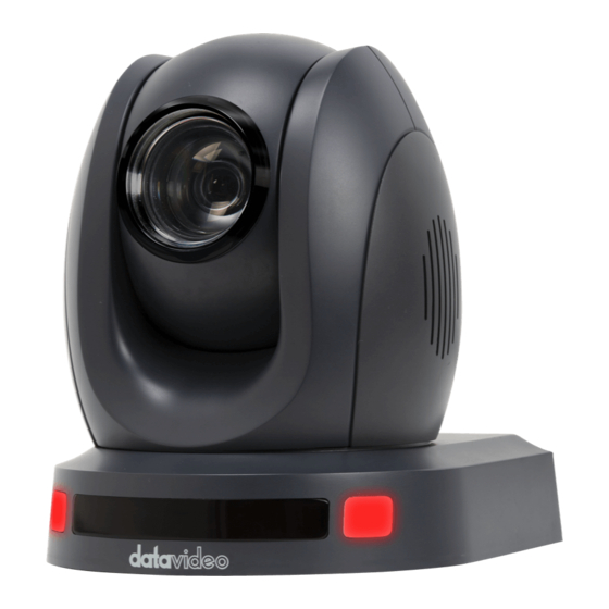
Location and Function of Parts Front of Camera Lens HD color camera with built-in 1/2.8" 2.07 megapixel CMOS sensor with white balance control, backlight compensation setting, auto gain setting and other functions. Tally LED When the tally signal is received, the tally lamp will light up. Remote Control Sensor Infrared receiver for remote control. - Page 12 Rear of Camera Power Input Port Connect the 12V power cord supplied with the product to the DC power port. The DC power adapter cable can be locked to the port using the outer ring locking mechanism. POE DVIP/LAN Port The POE DVIP/LAN Port is a bi-directional port that allows you to connect the camera over a network.
- Page 13 "Chapter 10 Remote Control Port Pin Definitions" for making the connection cable. RS-232 Interface (RJ-45) The PTC-145 can be connected to a remote controller or computer via the RS-232 interface. Use an Ethernet cable to connect to an external RS-232 controller and refer to "Chapter 10 Remote Control Port Pin...
- Page 14 Bottom of Camera Tripod screw holes Allows the user to mount the camera on a tripod. Screw Holes Screw holes for ceiling bracket installation. For Safety Rope Ties safety rope for fixing the camera to the ceiling.
-
Page 15: Basic Setup
You can view camera images through the Ethernet port, HDMI video output port, and 3G-SDI video output port. POE DVIP/LAN Perform the following steps to view the camera image in the web user interface. 1. Connect the PTC-145 to a PC or laptop via an Ethernet cable. -
Page 16: Hdmi Video Output
2. Open a web browser on the connected PC or laptop and enter the camera's default IP address into the address bar. Note: The default setting of PTC-145 is DHCP, if the camera is not assigned to an IP address, it will jump back to 192.168.100.100. -
Page 17: Remote Control And Osd Menu
5. Remote Control and OSD Menu Chapter 5 introduces the remote control functions and OSD menus. 5.1 Remote Control Function... - Page 18 Function Keys Descriptions Power button Power Button Tap this button once to enter standby mode. Tap it again to enter normal mode. Note: The power consumption in standby mode is about half of that in normal mode. Camera 1-4 The Camera 1~ Camera 4 buttons allow you to set your PTC- 145 camera to be numbered 1-4.
- Page 19 Move left/right to select different settings and press the Micro Joystick to confirm your selection. Reset IP Key Reset IP Key The default setting of PTC-145 is DHCP, if the camera is not assigned to an IP, it will jump back to 192.168.100.100.
- Page 20 Function Keys Descriptions STR Button STR Button Pressing this button together with the Preset 1-4 button allows you to save your desired preset settings. After you have set the desired settings and camera lens position, press the "STR" button and then press the Preset 1-4 number you want to save to save the preset successfully.
- Page 21 Function Keys Descriptions Auto-tracking Auto-tracking mode selector mode selector These three buttons allow you to select the auto-tracking mode you want. From left to right, the three auto-tracking modes are "full body", "half body" and "close shot".
-
Page 22: Osd Menu
5.2 OSD Menu The OSD menu allows the user to change many of the camera's settings. Press the [MENU] button on the remote control to enter the OSD menu as shown below. MENU Language Tracking Setup Camera P/T/Z Video Format Network Settings Version Restore Default... - Page 23 The following table lists the options of the main menu and its sub-menu. Main Options Video Restore Language Tracking Setup P/T/Z Network Version Camera Format Default Settings Tracking Restore Spped by English 1080P60 Exposure DHCP Protocol zoom Default IP Addr Traditional Zoom VISCA...
- Page 24 The OSD menu options are listed below. Main Menu Sub Menu Options Options English Language Traditional Chinese Simplified Chinese Tracking Tracking Mode Presenter Tracking Full Customized Figure Size Half-Body Close up Full Presetting Tracking Customized Presetting Half-Body Presetting Near Body Presetting Slow Track Speed Fast...
- Page 25 PELCOO-D PELCCO-P VISCA Address VISCA Address Fix ON/OFF PELCO-P Address 1-255 PELCO-D Address 1-255 2400 4800 9600 Baudrate 38400 115200 Auto Flip RED/GREEN Tally Light GREEN Auto Manual Mode Bright Camera Exposure EV Level Flicker 50Hz 60Hz...
- Page 26 G.Limit 0~15 F1.8 F2.0 F2.4 F2.8 F3.4 F4.0 Iris F4.8 F5.6 F6.8 F8.0 F9.6 1/60 1/90 1/100 1/125 1/180 1/250 1/350 1/500 Shutter 1/725 1/1000 1/1500 1/2000 1/3000 1/4000 1/6000 1/10000 Gain 0~36 Bright 0~14 Auto Manual Indoor Outdoor Color WB Mode OnePush 2400K...
- Page 27 2600K 2700K 2800K 2900K 3000K 3100K 3200K 3300K 3400K 3500K 3600K 3700K 3800K 3900K 4000K 4100K 4200K 4300K 4400K 4500K 4600K 4700K 4800K 4900K 5000K 5100K 5200K 5300K 5400K 5500K 5600K 5700K 5800K 5900K 6000K 6100K 6200K 6300K 6400K 6500K 6600K 6700K 6800K...
- Page 28 BG Tuning 0~255 0~255 100% 110% Saturation 120% 130% 140% 150% 160% 170%...
- Page 29 180% 190% 200% Brightness 0~32 Contrast 0~14 Image Sharpness...
- Page 30 Color B&W-Mode B&W DZoom Auto Focus Mode Manual OnePush Focus AF-Zone Center Bottom AF-Sensitivity Middle High Noise Reduction NR-3D Default Meeting Style Clarity Bright Soft When turned on, Zoom will gradually Speed by Zoom accelerate and decelerate. P/T/Z Zoom Speed Image Freezing Acc Curve Standard...
- Page 31 Slow Fast Fast Preset Speed Slow Middle Positive Joystick Pan Dir Negative Positive Joystick Tilt Dir Negative 1080P60 1080P50 1080I60 1080I50 1080P30 1080P25 Video Format 720P60 720P50 1080P59.94 1080I59.94 1080P29.97 720P59.94 DHCP Network Settings 192.168.100.100 IP Addr (If DHCP is OFF) Version Restore Default Restore Default (YES/NO)
-
Page 32: How To Use The Tally Light Option In The Osd Menu
6. How to use the Tally Light option in the OSD menu The "Tally Light" option in the PTC-145 OSD menu allows you to determine whether the camera's Tally light will illuminate in red or green depending on the settings of the "PVW (green when pressed)" and "PGM (red when pressed)"... - Page 33 Switcher’s “PVW” is set to “ON” and the “PGM” is set to “OFF” (take channel 1 as an example). At this time, the tally light of the camera will not be lit. The diagram below is a schematic diagram. ...
- Page 34 Switcher’s “PGM” is set to “ON” and the “PVW” is set to “ON” (take channel 1 as an example). At this time, the tally light of the camera will be lit in red. The diagram below is a schematic diagram. ...
- Page 35 Switcher’s “PGM” is set to “OFF” and the “PVW” is set to “ON” (take channel 1 as an example). At this time, the tally light of the camera will be lit in green. The diagram below is a schematic diagram. ...
- Page 36 Switcher’s “PGM” is set to “ON” and the “PVW” is set to “ON” (take channel 1 as an example). At this time, the tally light of the camera will be lit in green. The diagram below is a schematic diagram. ...
- Page 37 Switcher’s “PGM” is set to “OFF” and the “PVW” is set to “ON” (take channel 1 as an example). At this time, the tally light of the camera will be lit in green. The diagram below is a schematic diagram. ...
- Page 38 When OSD Menu’s “Tally Light” option is set in “OFF” No input source is selected by the switcher’s “PVW” and “PGM” (take channel 1 as an example), which means that the “PVW” and “PGM” channels are “OFF”. At this time, the camera’s tally light will not be lit.
- Page 39 Switcher’s “PGM” is set to “OFF” and the “PVW” is set to “ON” (take channel 1 as an example). At this time, the tally light of the camera will not be lit. The diagram below is a schematic diagram. ...
- Page 40 Switcher’s “PGM” is set to “ON” and the “PVW” is set to “ON” (take channel 1 as an example). At this time, the tally light of the camera will not be lit. The diagram below is a schematic diagram.
-
Page 41: Installation Instructions
Ceiling bracket (upper and lower plates) x 1 Ceiling Bracket (Upper and PTC-145 camera x 1 Lower Plates Additionally, you will also need the following to secure the ceiling bracket to the ceiling: PA4*30 self-tapping screw x 4 ... - Page 42 Using four PA4*30 self-tapping screws, affix the bracket’s upper plate to the ceiling. Upper Plate of Ceiling Bracket Step 3: Affix the bracket’s lower plate to the bottom of PTC-145 As depicted in the diagram below, use three PM3*5 screws to affix the bracket’s lower plate to the bottom of PTC-145.
- Page 43 Lower Plate of Ceiling Bracket Step 4: Mount the PTC-145 Camera to the ceiling Now push the PTC-145 camera into the bracket’s upper plate in the direction as indicated by the arrow in the diagram below. Make sure the two plates click into place.
- Page 44 Lower Plate of Ceiling Bracket Upper Plate of Ceiling Bracket Push the PTC-145 camera into the bracket’s upper plate in the direction as indicated by the arrow. Make sure the two plates click into place. Step 5: Final Ceiling Surface...
-
Page 45: Network Connection
Network Connection The Ethernet port on the back of the PTC-145 allows you to connect your computer to the camera via a fixed IP or DHCP connection. The PTC-145 is factory defaulted to DHCP mode. To access and modify network settings, you must first log in to the camera's web user interface. - Page 46 Please go to the PTC-145 product page on Datavideo's website https://www.datavideo.com/product/PTC-145 to download and install the DVIP Network Configuration Tool. Make sure your laptop or computer is also set to DHCP mode. Please use DVIP Network Configuration Tool to find out the IP address of PTC-...
- Page 47 Open a web browser on your computer and enter the PTC-145's DHCP dynamic IP address, in this case 192.168.50.128, into the address bar, then press the Enter key on your keyboard to open the web user interface's login page.
- Page 48 "Apply" button to set your camera's connection mode to DHCP mode or Fixed IP mode. To reset the IP mode of the PTC-145 to the factory default setting, press the “Default” button. The PTC-145 is factory defaulted to DHCP...
-
Page 49: Dhcp Mode
In the next two chapters, we will introduce how to turn on DHCP for the camera and the Fixed IP Connection mode separately. Note: To log out of the web user interface, click "Logout" at the top right of the page. 8.1 DHCP Mode DHCP, or Dynamic Host Configuration Protocol, is a network protocol that enables a server to automatically assign IP addresses within a domain to all... -
Page 50: Fixed Ip Mode
RJ-45 Ethernet cable and set it to the same domain. Since the PTC-145 is defaulted to DHCP mode, please log in to the Web UI in DHCP mode, click the "Network" option on the left side of the Web UI to enter... -
Page 51: Dvip
"Secondary DNS", and click the "Apply" button to reboot the PTC-145. And then the PTC-145 will then set your PTC-145 to the Fixed IP Mode. Then you can connect your PTC-145 to a computer or laptop on the same domain and enter the fixed IP address into the web browser address bar to open the PTC-145 Web UI, taking the fixed IP address "192.168.100.100"... - Page 52 Android: https://play.google.com/store/apps/details?id=com.datavideo.dvipnetconfig &hl=en_US iOS: https://itunes.apple.com/tw/app/dvip-network- config/id1177895983?mt=8 After installing the DVIP Network Configuration Tool, follow the steps below to search for connected DVIP devices and enter the relevant settings. Step 1: Open the DVIP Network Configuration Tool and select the Ethernet option you are connecting to from the "Network Interface"...
- Page 53 Step 3: Click "PTC-145" to display the Network Setup pop-up window Step 4: User can click "Host Name" to change the device name. If necessary, users can also click on the settings to change the value, then click "Save" to...
-
Page 55: Web Ui
PTC-145 Web UI A web-based user interface allows you to configure and operate the PTC-145 unit. 9.1 Camera Setup The "Camera Setup" option allows users to see a preview of what the camera will capture on the Web UI. In addition, it also allows users to control camera control parameters such as "Focus", "Zoom", "Speed... -
Page 56: Camera Control
CAMERA CONTROL For "Camera Control" related functions, see the table below. Function Keys Descriptions Live Image Preview Window This live image preview window allows you to preview the live images taken by the camera. Focus The Focus option allows the user to adjust the focus point. - Page 57 Function Keys Descriptions and use the "Focus Far" "Focus Near" buttons to adjust the focus manually. Zoom The Zoom option allows users to adjust the Zoom Tele and Zoom Wide of the camera lens. You can press the Tele button Wide button to zoom the camera lens in and out...
-
Page 58: Image Setting
Pressing this "Home" button returns the camera lens to its starting position. Preset storage and call keys The PTC-145 has 255 presets (0 - 254). Enter the preset number you wish to save into the "PRESET" field and press the "SAVE"... - Page 59 Function Keys Descriptions Bright It allows the user to adjust the brightness. Please use the slider to adjust the brightness. After adjustment, press the "Apply" button to complete the setting. Saturation It allows the user to adjust the saturation level. Use the slider to adjust the saturation, and press the "Apply"...
- Page 60 Function Keys Descriptions Exposure The exposure drop-down menu allows the user to select the desired exposure mode. There are "Auto", "Manual", "Shutter Priority", "Aperture Priority" and "Brightness Priority" modes to choose from. Auto: Fully automatic shutter speed and aperture settings with automatic adjustments for...
- Page 61 Function Keys Descriptions brightness and adjusts the appropriate exposure value. Press the "Apply" button to complete the setting. Dynamic Range The Dynamic Range drop- down menu allows you to set the dynamic range or turn off the dynamic range function. Press the "Apply"...
- Page 62 Function Keys Descriptions feature is currently not available. Auto Mirror The "Auto Mirror ON/OFF" switch allows the user to turn the auto mirror function on/off. When Auto Mirror is set to "ON", the screen will be displayed when a person is detected on the screen, regardless of whether the camera is in the upright position or...
- Page 63 Function Keys Descriptions function will be disabled. After adjustment, press the "Apply" button to complete the setting. AGC Automatic Gain Control This is the AGC automatic gain control function. This function is not available yet. 3DNR This is a 3D Noise Reduction function that allows you to select the level of 3D Noise...
-
Page 64: Video Output
9.2 Video Output The "Video Output" option allows users to select the desired video output resolution from a drop-down menu. The image output interface is shown below. After selecting your desired video output resolution, press the "Apply" button to complete the setting. In the upper right corner of the "Video Output"... - Page 65 For "Streaming" related functions, please refer to the following table. Function Keys Descriptions Streaming ON/OFF Switch You can press this ON/OFF switch to turn on or off the streaming function of "Main Stream" or "Sub Stream". Encoding Format This option allows you to select the encoding format for streaming video.
- Page 66 Function Keys Descriptions Bit Rate The bit rate is the amount of data required to encode an image in one second. From the streaming point of view, the higher the bit rate, the higher the quality, but it also requires more bandwidth. The default bit rate for the main stream is "8192 Kb/s".
- Page 67 Function Keys Descriptions Frame rate A high frame rate for a smoother viewing experience, the default frame rate is 25. I Frame Interval The shorter the I Frame interval, the higher the image quality. However, a larger bandwidth is required. Selecting a longer I Frame interval requires less bandwidth but results in a...
- Page 68 RTSP streaming RTSP Authorization If the "RTSP Authorization" option is set to "ON", when you want to stream RTSP, you need to enter your PTC-145 Web UI login password, which is defaulted to "admin", in the RTSP streaming video player to view your RTSP streaming video.
- Page 69 This is the SRT Caller mode. SRT Server Address If your PTC-145 is set to SRT Caller mode, you need to fill in the "SRT Server Address" field with the SRT server address you obtained from your SRT streaming platform.
- Page 70 Function Keys Descriptions the transmission delay time for SRT streams. The setting range is 20-8000. SRT Stream ID This is where you fill in the SRT Stream ID, which is usually provided by your CDN or cloud service platform. SRT streaming (SRT Listener mode) SRT Mode When SRT streaming is selected, you can choose...
- Page 71 Function Keys Descriptions Address This address is the location of the multicast, the default value is 224.1.2.3 Port This is the port number for the multicast function and the default value is 4000. ONVIF ONVIF Authorization This is the ON/OFF switch for ONVIF authorization.
- Page 72 Notes. 1. SRT Caller and RTSP Publish can only work on the "Main Stream". 2. When SRT Caller and RTSP Publish are working on the "Main Stream", the "Sub Streams" will have no function. Streaming to Youtube Please see the following steps to learn how to stream to Youtube. 1.
- Page 73 3. You will see the streaming key and streaming URL provided by Youtube streaming platform. Take the main stream as an example, please set the "Stream" > "Main Streaming ON/OFF" switch of PTC-145 Web UI to "ON" and select "RTMP(S)" in the "Protocol" drop-down menu, then please copy the "Stream URL"...
-
Page 74: Streaming To Facebook
4. Please restart the PTC-145 camera and you will see the start screen on the Youtube live stream page. Click the "END STREAM" button to end the live stream. Streaming to Facebook Below are the steps to set up a live streaming on Facebook Live Producer... - Page 75 Note: A single live stream on Facebook platform cannot exceed 8 hours. 2. Please click the "Select" button on the "Go Live" option as shown below. 3. Select the "Streaming Software" option and enter the title and description of your live video in the "Title" and "Description" fields. You can also choose whether or not to share the live stream to your Facebook story.
- Page 76 "RTMP(S)" from the "Protocol" drop-down menu, then please copy the "Server URL" and "Stream Key" separately and paste them into the "Streaming > MRL" field of the PTC-145 Web UI according to the format of "Stream URL/Stream Key". Finally, click the "Apply" button.
- Page 77 6. Please go to the "System" option and click the "Reboot" button to reboot the PTC-145. 7. After the reboot is complete, you can see a preview of the live screen captured by the PTC-145 camera in the "Video" option on the Facebook Live page.
- Page 78 8. Please set the relevant settings, including "Choose where to post" and "Select audience", and then click the "Start Live Streaming" button to live stream the footage captured by the PTC-145 immediately.
- Page 79 9. You will see the screen of the live stream that has been successfully carried out. If you want to end the live stream, please click the "End Live Video" button to end the live stream immediately. Live streaming using your personal Facebook page or fan page 1.
- Page 80 3. Select the "Streaming Software" option and enter the title and description of your live video in the "Title" and "Description" fields. You can also choose whether or not to share the live stream to your Facebook story. 4. Please click “Advanced Settings” and you will be able to see the " Server URL"...
- Page 81 "RTMP(S)" from the "Protocol" drop-down menu, then please copy the "Server URL" and "Stream Key" separately and paste them into the "Streaming > MRL" field of the PTC-145 Web UI according to the format of "Stream URL/Stream Key". Finally, click the "Apply" button.
- Page 82 PTC-145. 7. After the reboot is complete, you can see a preview of the live screen captured by the PTC-145 camera in the "Video" option on the Facebook Live page. 8. Please set the relevant settings, including "Choose where to post" and "Select audience", and then click the "Start Live Streaming"...
- Page 83 9. You will see the screen of the live stream that has been successfully carried out. If you want to end the live stream, please click the "End Live Video" button to end the live stream immediately.
-
Page 84: How To Do The Srt Streaming By The Vmix Software
How to do the SRT Streaming by the vMix Software How to install the Vmix Software Please install the vMix software according to following steps. 1. At first, please go to vMix official website and then download the vMix 60- day free-trial. - Page 85 4. Please click “I accept the agreement” and then click the “Next” button. 5. Please click the “Next” button. 6. Please click the “Next” button.
- Page 86 7. Please click the “Next” button.
- Page 87 8. Please click the “Install” button. 9. The installation will be started.
- Page 88 10. Please click the “Finish” button to finish the installation. 11. Please select “Register for a fully functional 60 Day Trial” to fill out your Email Address. After that, please click the “OK” button to open the vMix software.
- Page 89 12. Please select the initial resolution and frame rate that you want to use and then please click the “OK” button. 13. After opening vMix, the software interface is shown as following diagram.
- Page 90 Note: If vMix is set to Caller mode, then PTC-145 should be set to Listener mode. If vMix is set to Listener mode, the PTC-145 needs to be set to Caller mode.
- Page 91 Click the “Stream/SRT” option in the “Input Select” interface that opens, select SRT Caller in the Stream Type drop-down menu, and then enter the following field information: Enter the IP address of the connected device in the "Hostname" field, for example, 192.168.5.163 for PTC-145.
- Page 92 The "Port" field is entered by the SRT port number 9000 in "Streaming- >SRT Port" in the PTC-145 web UI. Enter the password 8888888888 set by the PTC-145 Web UI in the "Passphrase" field. The "Key Length" drop-down menu can be unselected.
- Page 93 Setting the PTC-145 to Caller Mode Go to the PTC-145 Web UI interface, click the “Stream” option, and then enter the information in the following fields: Click on the “Protocols” drop-down menu and select SRT. The "SRT Address" field enters the IP address of the device on which the Vmix software is installed.
- Page 94 Listener in the Stream Type drop-down menu, and then enter the following field information: Enter 1935 into the "Port" field (the "Host Port" value of the PTC-145 Web UI). Enter 8888888888 in the "Passphrase" field to match the SRT password...
- Page 95 The "Key Length" drop-down menu selects a key length of 32, which is consistent with the "SRT Key Length" setting in the PTC-145 Web UI. Finally, press the "OK" button. The images captured by the PTC-145 should be successfully streamed to the...
-
Page 96: Multicast
You can stream camera images via Multicast (multicast setting). Perform the following steps to stream TS on VLC media player. 1. On the “Stream” page of the PTC-145 Web UI, select “Multicast” from the “Protocol” drop-down menu. 2. Turn on VLC, click "Media""Open Network Stream" and enter udp://224.1.2.3:4000 to view the main streaming image and... -
Page 97: Network
9.4 Network The "Network Settings" option allows you to set the PTC-145's network- related settings including "DHCP ON/OFF" switch, "IP Address", "Subnet Mask", "Default Gateway", "Primary DNS", "Secondary DNS", etc. In addition, the "Network Settings" option also allows you to set the NTP-related settings including "Type", "Time Zone", and "NTP Server". - Page 98 If your camera is set to "DHCP OFF", then you need to manually fill in the fixed IP address you want. The PTC-145 is factory defaulted to DHCP mode. Subnet Mask If your camera is set to Fixed IP...
- Page 99 Function Keys Descriptions MAC Address This is the MAC Address and cannot be changed. Type This is the NTP (Network Time Protocol) setting type, and the default value is "Synchronize automatically from the network". Time zone You can select your desired time zone from the drop-down menu.
-
Page 100: Audio
9.5 Audio The "Audio" option allows you to set the PTC-145's settings including the "Audio Enable ON/OFF" switch, "Audio Input", "Encode Type", "Sample Rate", "Bit Rate", "Soundtrack" and "ADTS" options. The main interface of "Audio" option is shown below. For "Audio" related functions, see the table below. - Page 101 Function Keys Descriptions Encode Type This is the encoding format of the input sound, which is AAC format by default. Sample Rate This drop-down menu allows the user to select the desired sample rate for the input audio. The default value is 48K. Bit Rate This drop-down menu allows the user to select the bit rate.
-
Page 102: System
9.6 System "The "System" option allows you to set the PTC-145's “Camera Name”, “Language”, “Tally Mode”, and “Admin Password”. In addition, you can also see the current firmware version from the "Version" option. You can also click the "Browse"... - Page 103 Please refer to the following table for "System" related functions. Function Keys Descriptions Device Name You can enter your desired camera name in this field. Language You can use this drop-down menu to select the display language of the Web UI. Tally Mode You can set your camera's Tally Mode from this drop-...
- Page 104 Admin Password This option allows you to set your Admin password, which is the password you need to log in to the PTC-145 Web UI. The factory default password is "admin". When you have finished setting the password, press the "Apply"...
-
Page 105: Auto Tracking
9.7 Auto Tracking The "Auto Tracking" option allows you to set the PTC-145's "Auto Track Mode ON/OFF", "Auto Track Mode" selection, "Auto Zoom ON/OFF" switch, "Auto Tilt ON/OFF" switch, "Detect Indicator", "Tracking Start Position", "Tracking Tip", "Figure Size", "Select Object", "Placement", "AT Speed", etc. The main interface of the "Auto Track"... - Page 106 Function Keys Descriptions Auto Zoom ON/OFF Switch This is the Auto Zoom ON/OFF switch, which allows you to turn the camera's auto zoom function on or off. Auto Tilt ON/OFF Switch This is the Auto Tilt ON/OFF switch that allows you to turn the camera's auto pan/tilt function on and off.
- Page 107 Function Keys Descriptions function. If it is set to "OFF", the prompt is turned off. Figure Size The Figure Size option provides four preset settings, including "Full Body", "Half Body", "Close-up" and "Customized", which allow users to adjust the angle of the people that the camera wants to capture when in auto-tracking mode.
- Page 108 Function Keys Descriptions Placement This option allows you to set the position of the person you want to follow to be on the left, center, or right side of the screen when the camera captures the person you want to follow. There are three options for you to choose from: "Left", "Center"...
-
Page 109: Remote Control Port Pin Definitions
10. Remote Control Port Pin Definitions In addition to operating the PTC-145 remotely over Ethernet, you can also operate the PTC-145 by connecting it to a computer or any external controller via an RS-232 or RS-422/RS-485 remote port. You can connect an external RS-... - Page 110 The following are the pin definitions for the RS-422/RS-485 control port. RJ-45 connector Camera RS-422/485 Control Port White/Orange Orange White/Green Blue White/Blue Green White/Brown Brown How to connect the PTC-145 to a 2-wire RS-485 interface RJ-45 connector Camera RS-485 Control Port White/Orange Orange White/Green (RX-/TX-) Blue White/Blue Green (RX+/TX+)
-
Page 111: Firmware Update
V2.1.9 2024-01-07/ AF Version V1.0.4 2023-10-27) What to Prepare Before Firmware Upgrade The latest PTC-145 firmware update zip file x1. The latest firmware zip file can be downloaded from the PTC-145 product page on Datavideo's official website at https://www.datavideo.com/product/PTC-145 . After unzipping the downloaded firmware zip file, you can see two firmware files. - Page 112 System Connection Diagram Check Firmware Version Page 115 Before Updating the Firmware Page 118 Updating the MCU Firmware Page 121 Updating camera and AF firmware Page 123...
-
Page 113: Check Firmware Version
PTC-145 to the other LAN interface of the router. 3. Connect the DC 12V power adapter to the PTC-145 camera. 4. The factory default setting of the PTC-145 is DHCP mode. Make sure your laptop or PC is set to DHCP mode. - Page 114 7 You can see the DHCP IP address of the PTC-145. In this example, it is "192.168.50.73". 8. After obtaining the IP address of the PTC-145, enter the IP address in the browser address bar. After that, you will see the login page of PTC-145 Web UI.
- Page 115 Default User Name: admin Default Password: admin 9. Click the “System” option to open the Firmware Update page. You will then see the current firmware version of the PTC-145 camera.
-
Page 116: Before Updating The Firmware
PTC-145 to another LAN interface on the router. 3. Connect the DC 12V power adapter to the PTC-145 camera. 4. The factory default setting of the PTC-145 is DHCP mode. Make sure your laptop or PC is set to DHCP mode. - Page 117 PTC-145 product page on Datavideo's official website https://www.datavideo.com/product/PTC-145 6. Double-click the DVIP Network Configuration Tool to select the Ethernet card, and then click OK. 7 You can see the DHCP IP address of the PTC-145. In this example, it is "192.168.50.73".
- Page 118 8. After obtaining the IP address of the PTC-145, enter the IP address in the browser address bar. After that, you will see the login page of PTC-145 Web UI. Please enter the default username and password for logging into the Web UI.
-
Page 119: Updating The Mcu Firmware
11.3 Updating the MCU Firmware 1. Please make sure that you have unzipped the downloaded firmware. Then, press System->Browse to select the MCU firmware file "PTC145_ARM_V2.1.3_20240105.mrg". - Page 120 After the MCU firmware is updated successfully, the PTC-145 will reboot automatically. After the reboot is completed, please press the "Yes" button and log in to the PTC-145 Web UI again, then the whole MCU firmware update process is completed successfully.
-
Page 121: Updating Camera And Af Firmware
11.4 Updating camera and AF firmware 1. Make sure you have unzipped the downloaded firmware. Then, please click System->Browse to select the Camera and AF firmware files. “D- PTC145_NDI_SY20X_V2.1.9_R_20240107.mrg”. - Page 122 3. After the camera and AF firmware have been successfully updated, the PTC- 145 will automatically reboot. After the reboot is complete, press the "Yes" button and log in to the PTC-145 Web UI again. After that, the entire camera and AF firmware update process will be completed successfully.
-
Page 123: Frequently-Asked Questions
12. Frequently-Asked Questions This section describes the problems you may encounter when using this product. If you have any problems, please refer to the relevant section and try the suggested solutions. If the problem persists, please contact your local dealer or service center. Problems Solutions Important Points for... - Page 124 device is normal. 4. Make sure the OSD menu is closed. The remote control can only be used when the OSD is closed. The camera cannot be 1. Please make sure the cables are the controlled through the standard connection cables provided by serial port.
-
Page 125: Dimensions
13. Dimensions Unit: mm... -
Page 126: Specifications
14. Specifications Product Model PTC-145 Product Name HD Tracking PTZ Camera 1080p 60/59.94/50/30/29.97/25 Video 1080i 60/59.94/50 format/Resolution 720p 60/59.94/50 Image Sensor 1/2.8 inch high quality HD CMOS sensor Effective Pixels 2.07 Mega pixels (approx.) S/N Ratio ≥50dB Min. Illumination 0.5Lux (F1.8, AGC ON) - Page 127 Image Compensation Backlight Compensation HDMI x 1 Video Output 3G-SDI x 1 RJ-45 PoE x1 Audio Input 3.5mm Line in Tally LED Dual color (Red, Green) Lens Filter M52.0 x 0.75 Thread with UV Protection Pelco-D, Peldo-P, Control Protocol VISCA, VISCA over IP, DVIP, ONVIF Remote Control Web GUI...
- Page 128 F/W Update Via Web UI IR Control RMC-180 series/ Camera Control Unit RMC-300 series/ PTZ View Assist APP Tripod Mount 1/4-20 UNC Optional Accessories WM-1/ WM-10/ WM-11 Color Dark Blue/White Dimension (LxWxH) 156 x 184 x 186 mm Weight 1.6Kg Operating Temp.
- Page 129 Note...
- Page 130 Note...
- Page 131 Note...
-
Page 132: Service And Support
Service and Support www.datavideo.com/tw/product/PTC-145 Mar.-18 2024 Ver: E1...
Need help?
Do you have a question about the PTC-145 and is the answer not in the manual?
Questions and answers