Table of Contents
Advertisement
Advertisement
Table of Contents

Related Manuals for Datavideo PTC-140T


Summary of Contents for Datavideo PTC-140T
-
Page 2: Table Of Contents
TUDIO 4.4.1 Troubleshooting for the PTC-140T and the HS-1600T Connection .. 16 4.4.1.1 How to Set the Baud Rate of the PTC-140T Camera ....16 4.4.1.2 How to Set PTC-140T’s Video Format to be Consistent to HS- 1600T’s PGM OUT Resolution .............. 17 4.4.2 System Diagram for the PTC-140T and the HS-1600T Connection . - Page 3 9.2.2.2 Video Configure-Video Encode ..........51 9.2.2.3 Video Configure-Stream Publish..........55 9.2.2.3.1 How to Stream the PTC-140T Video to the RTMP Platform ..56 (Take Youtube as an Example) ............. 56 9.2.2.3.2 How to Stream the PTC-140 Video to the RTMP Platform ..57 (Take Facebook as an Example) ............
- Page 4 9.2.2.14 System User ................71 How to Set the User Name and Password for System User ....71 9.2.2.15 Update ................... 71 How to Update the Latest Firmware for the PTC-140T Camera ..... 72 9.2.2.16 Default ................... 72 9.2.2.17 Reboot ................... 73 9.2.3 Logout ..................
-
Page 5: Fcc Compliance Statement
7. This product should only be operated from the type of power source indicated on the marking label of the AC adapter. If you are not sure of the type of power available, consult your Datavideo dealer or your local power company. - Page 6 other risks, and will void your warranty. Refer all service issues to qualified service personnel. 13. Unplug this product from the wall outlet and refer to qualified service personnel under the following conditions: a. When the power cord is damaged or frayed; b.
-
Page 7: Warranty
Hard Drive, Solid State Drive, SD Card, USB Thumb Drive, Lighting, Camera module, PCIe Card are covered for 1 year. The three-year warranty must be registered on Datavideo's official website or with your local Datavideo office or one of its authorized distributors within 30 days of purchase. -
Page 8: Disposal
Disposal For EU Customers only - WEEE Marking This symbol on the product or on its packaging indicates that this product must not be disposed of with your other household waste. Instead, it is your responsibility to dispose of your waste equipment by handing it over to a designated collection point for the recycling of waste electrical and electronic equipment. -
Page 9: Product Overview
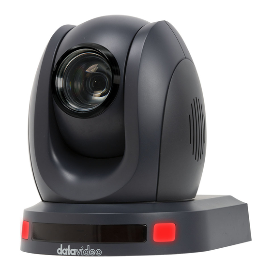
1. Product Overview The PTC-140T is a low-cost HDBT PTZ camera, which features PoE functionality, 20x optical zoom, 10 digital zoom, transmitting the uncompressed video up to 100 meters (1080p60/50). The PTC-140T is an IP camera as well, supports H.264 /H.265 video compression and dual stream output. -
Page 10: Location And Function Of Parts
3. Location and Function of Parts Front of Camera Lens Built-in 1/2.8” 2.07M Pixel CMOS HD color camera with white balance control, backlight compensation settings, automatic gain settings and etc. Tally LED Tally lamp lights up when tally signal has been transmitted to the tally signal box. - Page 11 Rear of Camera Power Input DC in socket connects the supplied 12V PSU. The connection can be secured by screwing the outer fastening ring of the DC In plug to the socket. LAN Port This port is used to output the video of the camera. Please connect a Ethernet cable from this port to the LAN port of a PC or Notebook PC and then users can monitor the video of the camera from the web control interface.
- Page 12 Bottom of Camera Tripod Screw Hole allows the user to mount the camera on the tripod. Screw Hole Screw holes for ceiling bracket mounting. Safety Rope Loop Safety rope loop for fixing the camera.
-
Page 13: Connections
4. Connections 4.1 Camera Rear Control Panel HDBaseT Port for connection to the PTC-140T Receiver Box HDBaseT port using a CAT5e/6 cable. 4.2 Receiver Box Front Panel... - Page 14 HDBaseT Port for connection to the PTC-140T Camera HDBaseT Port using a CAT5e/6 Cable RS-232/RS-422 Interface (Phoenix Terminal) Connects to external RS-232/RS-422 device. RX: Receiver PIN (differential pair if using RS-422 connection) TX: Transmitter PIN (differential pair if using RS-422...
-
Page 15: Receiver Box Rear Panel
Connect the DVIP port to an Ethernet switch or router, serving as a communication port between the network and the HBT-11 receiver. Note: The HBT-11 is not the accessory of the PTC-140T, The HBT-11 will be packaged only with the PTC-140TH. -
Page 16: How To Connect The Ptc-140T Camera To The Hs-1600T Hdbaset Portable Video Streaming Studio
The Factory Default Baud rate for the HS-1600T is 38400 and this value can not be changed by users. The Factory Default Baud rate for the PTC-140T is set at 38400 and there is no need for users to change it. However, if there is something wrong when connecting the PTC-140T with the HS-1600T, please check whether the Baud rate of the PTC-140T is changed or not. -
Page 17: How To Set Ptc-140T's Video Format To Be Consistent To Hs-1600T's Pgm Out Resolution
Step 5. Please press the “Left” key or “Right” key to set the Baud rate at 38400. Please make sure that the Baud rate of the PTC-140T and the Baud rate of the HS-1600T must be consistent to assure their normal operation. - Page 18 Step 12. Please select the “Yes” button by using the “Left or Right Arrow” key and then please press the “Enter” button on the keyboard of the HS-1600T to save the updated settings. The system diagram for the PTC-140T and the HS-1600T connection is shown as following diagram.
-
Page 19: System Diagram For The Ptc-140T And The Hs-1600T Connection
4.4.2 System Diagram for the PTC-140T and the HS-1600T Connection... -
Page 20: Basic Setup
140T camera to the HDBaseT port on the front panel of the HDBaseT receiver box. Step 2. Please connect a HDMI cable from the HDMI OUT port to the HDMI port of the external connected monitor. Step3. After the self-test of the PTC-140T camera is done, the video will be shown. -
Page 21: Remote Control And On-Screen Menu
6. Remote Control and On-Screen Menu 6.1 Remote Control Functions Item Description Standby button After pressing the Standby button for 3 seconds, the camera will do the self-test again and then go back to the Home position. (Note: If power-on mode is turned on and Preset 0 is set, and there is no operation within 12s, it will automatically... - Page 22 The * and # keys are used for key combination. The PTC-140T provides 17 key combinations for users which are shown as *, # Keys follows. (1) 【#】+【#】+【#】: Clear all presets. (2) 【*】+【#】+【6】: Restore factory defaults (3) 【*】+【#】+【9】: Switch images between normal & Up- side down position.
- Page 23 zooming out and stops as soon as the key is released. SET PRESET SET PRESET This key is used for users to set presets. For Setting Preset Please press the SET PRESET key plus the 0-9 number keys and then the preset is set successfully. CLEAR PRESET CLEAR PRESET This key is used for users to clear preset.
- Page 24 Camera Remote Controller Address Setting Camera Remote Controller Address Setting Keys The F1 to F4 keys are used for users to set the camera remote controller addresses. Set the camera address as No.1: Please press 【*】+【#】+ 【F1】from the remote controller. Set the camera address as No.2: Please press 【*】+【#】+ 【F2】from the remote controller.
-
Page 25: On-Screen Menu (Control By Remote Controller)
6.2 On-Screen Menu (Control by Remote Controller) On-Screen Menu allows the user to change various camera settings such as shooting conditions and the system setup. The PTC-140T provides several options in the first layer OSD MENU including Language, (Setup), (Camera), (P/T/Z), (Video Format), (Version) and (Restore Default). - Page 26 Details of all options in the on-screen menu are listed in the table below. First Level Second Level Third Level Fourth Level Sub-Option Main Options Sub-Options Parameters Parameters Descriptions 1. Language (English/Simpli fied Chinese) 1. Auto 2. VISCA Protocol 3. PELCOO-D 4.
- Page 27 Gain Limit 0~15 Closed Auto 3000K 3500K 4000K 4500K 5000K WB Mode 5500K 6000K 6500K 7000K Manual Onepush RG Tuning Color BG Tuning...
- Page 28 100% 110% 120% Saturation 130% 140% 150% 160% 170% 180% 190% 200% High AWB Sensitivity Middle Brightness Image Contrast...
- Page 29 Sharpness Flip-H Flip-V Color B & W Mode Black & White Default 0.45 Gamma 0.50 0.55 0.63 DZoom Closed Auto Focus Mode Manual Onepush Focus AF-Zone Center Bottom...
- Page 30 High AF-Sensitivity Middle Auto NR-2D Noise Reduction NR-3D Dynamic Hot Pixel Default Normal Style Clarity Bright Soft Zoom by Speed Zoom Speed 4. P/T/Z Image Freezing Slow Acc Curve Fast 1080P60 1080P50 1080I60 1080I50 5. Video 1080P30 Format 1080P25 720P60 720P50 1080P59.94...
- Page 31 1080I59.94 1080P29.97 720P59.94 MCU Version Camera Version 6. Version AF version 7. Restore Restore Default (Yes/No) Default...
-
Page 32: Installation Instructions
4, PA4 plastic screw stopper x 4, PM3x5 screw x 6, ceiling upper covering plate x 1, ceiling lower covering plate x 1 and PTC-140T camera x 1 are needed. Step 1. The Ceiling Bracket, Ceiling Upper Cover Plate and Ceiling Lower Covering Plate ... - Page 33 Step 2. Mount the Ceiling Upper Covering Plate to the Ceiling At first, Please screw 4 PA4 plastic screw stoppers into the ceiling as shown as following diagram. Please connect the ceiling upper covering plate to the screw stoppers by using 4 PA4*30 self-tapping screws.
- Page 34 Step 3. Mount the PTC-140T Camera to the Ceiling Lower Covering Plate Please screw the PTC-140T camera to the ceiling lower covering plate by using 3 PM3*5 screws as shown as following diagram.
- Page 35 Step 4. Mount the PTC-140T Camera with the Ceiling Lower Covering Plate to the Ceiling Upper Covering Plate on the Wall Please push the PTC-140T camera with the ceiling lower covering plate according to the direction of following diagram and then please hook the ceiling lower covering plate to the ceiling upper covering plate.
-
Page 36: Direct Connection To Camera
8. Direct Connection to Camera To use the PTZ Camera Control Unit to directly control the PTC-140T camera, connect the Mini-Din 8 pin RS-232 port on the camera’s rear panel to the DB9 pin RS-232 port on the control keyboard or PC by a Mini-Din 8 pin to DB9 pin adapter cable. -
Page 37: Rs-232 Mini-Din 8 Pin Definition
8.1 RS-232 Mini-Din 8 Pin Definition Port Definition Data Terminal Ready Data Set Ready Transmit Data System Ground Receive Data System Ground IR OUT IR Commander Signal No Connection 8.2 RS232 (DB9) Pin Definition Port Definition Data Carrier Detect Receive Data Transmit Data Data Terminal Ready System Ground... -
Page 38: Ptc-140T's Web-Based User Interface
PTC- 140T. Note: The HBT-11 is not the accessory of the PTC-140T, The HBT-11 will be packaged only with the PTC-140TH. 9.1.1 Connect the Camera to the PC in DHCP Mode Please follow following steps for connecting the PTC-140T camera to the PC in DHCP Mode. - Page 39 Step 8. Please connect an RJ-45 Ethernet cable from the RJ-45 port of your PC to the LAN port of the router. Step 9. The default IP mode for the PTC-140T is Static IP mode. So please set your PC in Static IP mode in advance. Since the Static IP address of the PTC- 140T is 192.168.5.163, the IP address for your PC must be set in 192.168.5.x...
- Page 40 Step 11. Please enter the default User Name and Password and then click the Login button. The Default User Name: admin The Default Password: admin Step 12. Please click the “Configuration” option of the web UI and then click the “Ethernet” option. After that, please check the “DHCP” checkbox and then click the “Save”...
- Page 41 Step 13. Please click the “Reboot” button from the Reboot option to reboot the camera. Step 14. Please set the network setting of your PC in DHCP mode.
-
Page 42: Connect The Camera To The Pc In Static Ip Mode
PTC-140T. Step 2. Please connect an RJ-45 Ethernet cable from the HDBaseT interface on the rear panel of the PTC-140T camera to the HDBaseT interface on the front panel of the HBT-11 Receiver Box. Step 3. Please connect a 48V power adapter to the DC IN 48V interface on the rear panel of the HBT-11. - Page 43 Step 9. The default IP mode for the PTC-140T is Static IP mode. So please set your PC in Static IP mode. Since the Static IP address of the PTC-140T is 192.168.5.163, the IP address for your PC must be set in 192.168.5.x Step 10.
-
Page 44: Introduction Of The Ptc-140T Web User Interface
Step 12. After logging into the PTC-140T web UI, the main interface of the web UI will be shown. Note: If the real-time scene that is shot by the camera can not be previewed by users after logging in the web UI, please press the button “Get ADOBE FLASH PLAYER”... - Page 45 Preview Window This Preview windows allows users to see the real-time preview of the scene that is shot by the PTC-140T camera. Click the Preview Window once to enter the Full Screen mode and then click it once to back to original Preview Window.
- Page 46 Pan & Tilt Directions Control Buttons Users can control directions of pan and tilt of the PTC-140T camera lens by using those buttons. :Up Left Button :Up Button :Up Right Button : Left Button : Home Button Right Button : Down Left Button...
- Page 47 Zoom In/Zoom Out Control Please press the Zoom In button for zooming in the camera lens. Please press the Zoom Out button for zooming out the camera lens. Focus In/Focus Out Control Please press the Focus In button for focusing in the camera lens. Please press the Focus Out button for focusing out the...
-
Page 48: The Operations Of Zoom And Focus Buttons In Different Focus Modes
9.2.1.2 How to Set the Preset Positon Please follow following steps for setting your desired preset. Step 1. Please adjust the pan and tilt of the PTC-140T camera to your desired position. Step 2. Please make sure that other parameters including Zoom, Focus and those parameters in the Configuration option are set in advance. -
Page 49: How To Recall The Pre-Saved Preset
The default number of the PTZ speed control slider is 50 and the range for adjusting is from 0 to 100. Please follow following steps for adjusting the PTZ speed of the PTC-140T camera. Step 1. Please slide the PTZ speed control slider to the left side to reduce the pan and tile speed of the camera lens according to the number. - Page 50 Please see following table for the introduction of Audio Configure. Enable This Enable check box allows users to enable the settings for the parameters in the Audio Configure option. Encode Type This drop-down menu allows users to select their desired Encode type for the input audio source.
-
Page 51: Video Configure-Video Encode
audio source to be Mono or Stereo. Input Volume This slider allows users to adjust the volume of the input audio source. The range is from 1 to 10. The higher the value, the louder the volume of the input audio source. Save Button Please press this Save button to save the “Audio Configure”... - Page 52 including H.264 and H.265. Profile This drop-down menu allows users to select different profile options including BP (Baseline Profile), MP(Main Profile) and HP(High Profile) for main stream. Image Size This drop-down menu allows user to select their desired image size for the main stream. Rate Control This drop-down menu allows users to select CBR or VBR.
- Page 53 I Frame Interval This column allows users to set the I Frame Interval. The default value is 75. The shorter I Frame Interval causes higher quality video. However, it needs more network bandwidth. If the I Frame Interval is set to be longer, it needs less bandwidth.
- Page 54 Image Size This drop-down menu allows user to select their desired image size for the sub stream. Rate Control This drop-down menu allows users to select CBR or VBR. CBR encoding does not optimize media files for quality but will save you storage space.
-
Page 55: Video Configure-Stream Publish
9.2.2.3 Video Configure-Stream Publish The Stream Publish function allows user to stream the main stream and sub stream of the PTC-140T by the RTMP streaming protocol. Please see following table for the introduction of parameters of the Stream Publish option. -
Page 56: How To Stream The Ptc-140T Video To The Rtmp Platform
Step 1. Please make sure the PTC-140T and other devices are successfully connected. Step 2. Please obtain the stream server address and the stream token from the Youtube platform. Step 3. Please open the web UI of the PTC-140T and then select the Stream Publish option. -
Page 57: How To Stream The Ptc-140 Video To The Rtmp Platform
WAN port of a router. Step 2. Please use another RJ-45 Ethernet cable to connect one end to the LAN port on the rear panel of the PTC-140T camera and then connect another end to one of the LAN port of the router. - Page 58 “Server URL” and “Persistent Stream Key”. After that, please paste the “Server URL” into the Host Address column of the PTC-140T web UI. Finally, please paste the “Persistent Stream Key” into the Stream Name column of the PTC-140T web UI.
-
Page 59: Rtp Multicast
9.2.2.4 RTP Multicast The RTP Multicast option allows users to set RTP/TS multicast related parameters. The main interface of the RTP Multicast is shown as following. Please follow following steps for the RTMP Multicast. Step 1.Please download VLC media player from the website https://www.videolan.org Step 2. - Page 60 1. Focus Option Focus option provides users to set Focus Mode, AF-Zone and AF-Sensitivity. Focus Mode: Users can select Auto, Manual and One Push from the drop down menu. AF-Zone: Users can select Top, Center, Bottom and All from the drop down menu.
- Page 61 2. Exposure Option The exposure option allows users to set Exposure Mode, EV, BLC, Anti-Flicker, Gain Limit and DRC. Mode: Auto, Manual, SAE, AAE and Bright EV: ON, OFF. If the EV is turned on, there is an EV adjustment slider for users to adjust the EV level.
- Page 62 3. Color The Color option allows user s to set WB Mode, RG Tuning, BG Tuning, Saturation, Hue and AWB Sensitivity. WB Mode: Auto/3000K/3500K/4000K/4500K/5000K/5500K/6000K/6500K/7000K/Manual /One Push RG Tuning: -10/-9/-8/-7/-6/-5/-4/-3/-2/-1/0/1/2/3/4/5/6/7/8/9/10 BG Tuning: -10/-9/-8/-7/-6/-5/-4/-3/-2/-1/0/1/2/3/4/5/6/7/8/9/10 Saturation: 60%/70%/80%/90%/100%/110%/120%/130%/140%/150%/160%/170%/180% /190%/200% Hue: 0/1/2/3/4/5/6/7/8/9/10/11/12/13/14 AWB Sensitivity: Low/Middle/High...
- Page 63 4. Image The Image option allows users to set several parameters including Bright, Contrast, Sharpness, Gamma, DCI, B & W Mode, Flip-H, Flip-V and DZoom. Bright: 0/1/2/3/4/5/6/7/8/9/10/11/12/13/14 Contrast: 0/1/2/3/4/5/6/7/8/9/10/11/12/13/14 Sharpness: 0/1/2/3/4/5/6/7/8/9/10/11/12/13/14/15 Gamma: Default/0.45/0.50/0.55/0.63 DCI: OFF/1/2/3/4/5/6/7/8 B & W Mode: Color/B & W Flip-H: OFF/ON Flip-V: OFF/ON DZoom: OFF/ON...
- Page 64 5. NR The NR option allows users to set NR-2D, NR-3D and Dynamic Hot Pixel. NR-2D: OFF/1/2/3/4/5/6/7/Auto NR-3D: OFF/1/2/3/4/5/6/7/8 Dynamic Hot Pixel: OFF/1/2/3/4/5...
- Page 65 6. Style This Style option allows users to select their desired Style including Default, Normal, Clarity, Bright and Soft from the drop-down menu. Note: For all parameters in the Video Parameters option, please click the Refresh button each time when the parameters are changed. The parameters will be effective immediately once they are changed.
-
Page 66: Video Osd
9.2.2.6 Video OSD The Video OSD option allows users to show time and title on the screen. Moreover, it allows users to determine font color and OSD offset of time and title. Please see following diagram for the main interface of the Video OSD. How to Show Time and Title on the Screen Please follow following steps for showing Time and Title on the Screen. -
Page 67: Osd Font Size
9.2.2.7 OSD Font Size The OSD Font Size option allows users to determine the OSD font size of the master stream and slave streams. Please see following diagram for the main interface of the OSD Font Size. Please check the checkbox of “According to the resolution” “Scale Size automatically”... -
Page 68: Network Configure-Network Port
How to Change the Video Output Resolution Please follow following steps for changing the video output resolution. Step 1. Please select your desired video output resolution from the Video OUT Format drop-down menu. Step 2. Please click the “Save” button and then the video output resolution is set successfully. -
Page 69: How To Set The Camera In Dhcp Mode
How to Set the Camera in DHCP Mode Please follow following steps for setting the camera in DHCP mode. Step 1. Please check the checkbox of DHCP. Step 2. Please click the “Save” button. Step 3. Please click the Reboot option and then click the Reboot button . -
Page 70: How To Change The Osd Language
How to Change the OSD Language Please follow following steps for changing the OSD language of the camera. Step 1. Please select your desired language from the Language drop-down menu. Step 2. Please press the “Save” button and then the OSD language is set successfully. -
Page 71: System User
9.2.2.14 System User The SysUser option allows users to set User Name and Password for accounts for three authorities including admin, user 1 and user 2. Please see following diagram for the main interface of System User. How to Set the User Name and Password for System User Please follow following steps for setting User Name and Password for system users. -
Page 72: How To Update The Latest Firmware For The Ptc-140T Camera
How to Update the Latest Firmware for the PTC-140T Camera Please follow following steps for updating the latest firmware for the PTC- 140T camera. Step 1. Please download the latest firmware of the camera from Datavideo Official website https://www.datavideo.com/product/PTC-140T Step 2. Please download the latest firmware and then save the firmware in the hard disk of your PC. -
Page 73: Reboot
9.2.3 Logout The Logout option allows users to logout the web-based user interface of the PTC-140T. Please follow following steps for logging out the web UI of the camera. Step 1. Please click the “Logout” option from the web based user interface. -
Page 74: Firmware Update
How to Update the Latest Firmware for the PTC-140T Camera Please follow following steps for updating the latest firmware for the PTC- 140T camera. Step 1. Please download the latest firmware of the camera from Datavideo Official website https://www.datavideo.com/product/PTC-140T Step 2. Please download the latest firmware and then save the firmware in the hard disk of your PC. -
Page 75: Frequently-Asked Questions
11. Frequently-Asked Questions This section describes problems that you may encounter while using the PTC- 140T. If you have questions, please refer to related sections and follow all the suggested solutions. If problem still exists, please contact your distributor or the service center. - Page 76 Sometimes 1. Please check whether the cable connection there is no between the camera and the external connected image? monitor is connected correctly. Image jittering 1. Please check whether the camera is well-mounted. is happened 2. Whether there is a vibrating machine or object that when the is around the camera.
- Page 77 The camera 1. Please check whether the control cable is the standard control cable that is provided by our can not be company. controlled by the serial port. 2. Please check whether the protocol, baud rate and address of the device that is connected are consistent to the protocol, baud rate and address of the camera.
-
Page 78: Dimensions
12. Dimensions Unit: mm... -
Page 80: Specifications
13. Specifications Camera Parameter Image Pickup 1/2.8 inch high quality HD CMOS sensor Element Optical Zoom Ratio 20x Optical Zoom Focal Length 5.2~98mm Effective Picture Approx. 2.07 Mega pixels Elements 1080p60/59.94/50/30/29.97/25 Signal System 1080i60/59.94/50 720p60/50/59.94 Angle of View Approx. 54.7 degrees (WIDE END) / 3.3 degrees (TELE (Horizontal) END) IRIS... - Page 81 S/N Ratio >55dB Input/Output Interface HDBaseT (PoE) x1 Image Interface RJ-45 x1 Video Compression H.264, H.265, Dual stream output Format VISCA/Pelco-D/Pelco-P; Control Protocol Baud Rate:115200/38400/9600/4800/2400bps, DVIP 3.5mm mic in/line in (not available) Audio Input Interface Audio Compression AAC/MP3/PCM Audio compression Format HDBaseT/IP Cam Audio Output...
- Page 82 1.592Kg Weight Remote Control (IP) Remote Upgrade, Reboot and Reset IR Remote Controller, DC 12V adaptor, Ceiling Mount Accessories Bracket OSD Language English, Simplified Chinese...
-
Page 83: Cable Selection
Cable Selection Video Resolutions (HDBaseT Connection) Cable Range Video Resolution Up to 1080p, 60Hz, 36 bpp. 100 meters Data rates lower than 5.3 Gbps or below 255 MHz CAT5e/6 TMDS clock. 70 meters Ultra HD video formats: HDMI Deep color: 1080p, 60, 48 bpp. 4K x 2K CAT6a/CAT7 100 meters(*) -
Page 84: Service & Support
Apr..-22.2019 Ver:E3...
Need help?
Do you have a question about the PTC-140T and is the answer not in the manual?
Questions and answers