Table of Contents
Advertisement
Quick Links
Advertisement
Table of Contents

Related Manuals for birddog P120


Summary of Contents for birddog P120
- Page 1 FULL NDI® PTZ CAMERAS. LEVELLED UP. USER GUIDE NDI 5 2022...
-
Page 2: Table Of Contents
What’s in the Box? ....................... 6 Optional Accessories ....................6 Quick Start Guide ......................7 Basic Connections........................7 Power Up............................7 Computer, say hello to P120 ....................7 Basic Configuration ........................8 Camera Connections ....................11 Remote Controller ...................... 13 Powering P120 ......................14 Thermal Management .................... - Page 3 Controlling the Camera with the Remote Controller ........20 Panning and Tilting ........................20 Zooming ............................21 Focusing ............................21 Shooting with Back Lighting ....................21 Changing Resolution ....................... 22 Storing the Camera Settings in Memory Using Presets ..........22 Operating Multiple Cameras with the Infrared Remote Controller .......23 Web Configuration Panel ..................
- Page 4 Controlling Your Camera Via Other Protocols ..........39 Camera Initial Setting Status Information ................39 VISCA over IP Control......................40 Setting the DIP Switch ......................41 Using RS-232 (VISCA) ......................43 Using RS422(VISCA) / RS485 (PELCO P/D) ..............45 PELCO P/D Keyboard RS485 Connection ..............48 Operating Multiple Cameras using RS-232 and 422/485 ..........
- Page 5 Copyright Copyright 2022 BirdDog Australia all rights reserved. No part of this manual may be copied, reproduced, translated, or distributed in any form or by any means without prior consent in writing from our company. Trademark Acknowledgement and other BirdDog trademarks and logos are the property of BirdDog Australia. Other trademarks, company names and product names contained in this manual are the property of their respective owners.
- Page 6 Maintenance Precautions • If there is dust on the front glass surface, remove the dust gently using an oil-free brush or a rubber dust blowing ball. If there is grease or a dust stain on the front glass surface, clean the glass surface gently from the •...
-
Page 7: Welcome To Birddog
Firmware Upgrade Before you use your new P120, it’s a good idea to upgrade to the lastest firmware. We are always adding new features and improving the performance of our products, so installing the latest firmware will provide you with the best user experience. -
Page 8: Birddog P120 Overview
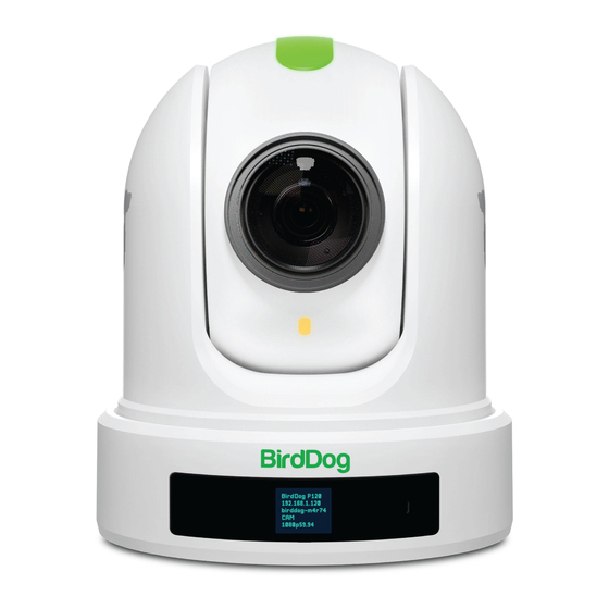
BirdDog P120 Overview Camera Features Resolution: Up to 1080P60, 1080i60 • • Lens: 5.2-104mm Zoom: Optical 20X Digital: 16X • Shutter Speed: 1/1 – 1/10,000 sec • Image stabilizer and true WDR 130dB • Video Output: HDMI, 3G-SDI, NDI® and USB video. -
Page 9: Welcome To The Future
BirdDog has been on the NDI® journey since the very beginning, and your P120 is just one of our products designed to take advantage of the features and potential of NDI®. -
Page 10: What's In The Box
What’s in the Box? NOTE: The camera color may be white or black in colour depending on the item purchased. Optional 1x BirdDog P120 1x IR Remote Controller (3V CR2032 Coin Lithium Battery Required) 1x camera Power Adaptor 1x bag of Camera Mounting Screws and Tally Light Number Inserts 1x USB to 3.5mm Audio Cable... -
Page 11: Quick Start Guide
Quick Start Guide If you are new to the world of NDI® or BirdDog cameras, please follow this quick start guide to become familar with the basic setup of your new camera. You can also view a similar online video. -
Page 12: Basic Configuration
The BirdUI BirdDog cameras have a web interface (BirdUI) that is displayed by your computer brower and can be used to configure your camera remotely. Click on the gear icon on the bottom right of the Studio Monitor window. - Page 13 You can choose to embed audio from the audio input connector into the NDI® stream or mute it. NDI Failover Source If the selected HDMI source is interrupted for any reason, P120 can automatically switch to a pre-determined alternative NDI® source. Select an available NDI® source for the failover function from the Available NDI® sources dropdown list.
- Page 14 Address information according to the requirements of your network. DHCP Timeout, Fallback IP address, Fallback Subnet Mask You can set the timeout period during which P120 will look for a DHCP IP address. After this period, the camera will default to the designated fallback IP address.
-
Page 15: Camera Connections
Camera Connections 1. 12V DC Power Port Connect the supplied DC power adaptor. 2. NDI Ethernet Port For VISCA over IP control and NDI® output. Supports PoE+(IEEE802.3at). 3. HDMI Port (HDMI 1.4) 4. 3G-SDI Video Output 5. RS-232/422 Control Port (RJ45) RJ45 to RS-232/422 convertor cable is provided. - Page 16 11. OLED Display Displays camera model, IP address, camera name and resolution. 12. Tally light number 13. Fixed Mounting Holes For original wall/ceiling mount bracket 14. Tripod mounting holes 15. Base DIP Switch Used for setting the camera configuration. For details, refer to Setting the DIP Switch.
-
Page 17: Remote Controller
Remote Controller 1. Power Power ON the camera to set the camera to operational • status. Power OFF the camera to set the camera to standby status. • When the camera is powered OFF, the camera turns to the • rear. -
Page 18: Powering P120
P120 can be powered in two ways. PoE+ (Power over Ethernet) • PoE+ is a convenient way to power P120 as it allows both data and power to be sent through the same standard Ethernet cable. The network switch must support PoE+ (802.3at). DC Connection •... -
Page 19: Video Output
Video Output The camera can simultaneously output SDI, HDMI, NDI® and USB (UVC) video. HDMI Signal Connect the camera to a HD monitor/TV using HDMI cable. Turn on the camera. After initialization, video will display on the monitor. Information of the camera initial setting status will display on the monitor for 5 seconds. You can set the displayed video format in the camera System menu. -
Page 20: Using The Camera Menus
Using the Camera Menus You can use the infrared remote controller to change camera settings while viewing the On Screen Display (OSD) menus on a connected monitor. The OSD is viewable over NDI , SDI or HDMI. ® However, the Web Configuration Panel (BirdUI) affords greater control of your camera with more parameters as well as allowing remote adjusting of camera settings over NDI... -
Page 21: Camera Menus
Camera Menus Exposure Menu The Exposure menu sets items related to exposure. Mode Full Auto: The exposure is adjusted automatically using the value set for EX-COMP. Manual: Allows manual adjustment of the GAIN, shutter speed (SPEED) and iris (IRIS). Iris Pri: Iris Priority mode. This mode allows you to set a fixed IRIS and EX-COMP with exposure achieved by automatic setting of SPEED and GAIN. -
Page 22: Picture 1 Menu
ATW (Auto tracking white balance): Auto Tracking White balance (2000K to 10000K), allows the camera to adjust the white balance according to the temperature of the light source illuminating the subject. User: This is a mode that enables you to manually set the control of Red and Blue gain up to 256 steps. Manual: Allows manual setting of the color temperature. -
Page 23: System Menu
Zoom Ratio OSD Determines whether the zoom ratio displays on screen. Video Parameters When set to ON, the value of the settings will be displayed on screen when you use remote controller to adjust the camera image parameters using the direct adjust buttons “+” or “-” with the feature keys on the remote controller. Adaptive P/T When set to ON, P/T speed are adaptive to the zoom range. -
Page 24: Controlling The Camera With The Remote Controller
Video Format You can change the camera video format. Select VIDEO FORMAT, press the “←” button to choose the video format, then press “→” (Pressing “→” button changes the value on some product models) or HOME button to confirm. After confirmation, press the HOME button again to restore it. The camera will reboot by itself and the new video format is activated. -
Page 25: Zooming
To set the remote to move the camera toward the opposite direction from that of the button you pressed, press the 2 (REV) button while holding down the L/R DIRECTION SET button. Arrow Button Movement of the Camera Setting L/R DIRECTION SET While holding down Press NOTE:... -
Page 26: Changing Resolution
Changing Resolution Press the RESOLUTION button. Use the arrow keys to navigate the displayed menu. Press Home to select. Screen will display ‘CHANGING…” Press Menu to exit. Storing the Camera Settings in Memory Using Presets Using the preset function, six sets of camera shooting conditions can be stored and recalled. The six sets of camera shooting conditions can be stored and recalled by using remote controller. -
Page 27: Operating Multiple Cameras With The Infrared Remote Controller
NOTE: When the power is turned on, the camera starts with the settings stored in POSITION 1, so if you want • to retain the previous pan and tilt positions, store those positions in POSITION 1. When you are storing or cancelling the settings in one POSITION, you cannot call up, store or cancel •... -
Page 28: Web Configuration Panel
In order to access the BirdUI on a network which is configured to a different subnet, change your computers IP address to match the BirdDog unit. Once you gain access to the BirdUI, choose your IP address to match the rest of the devices on your network. -
Page 29: Birdui Layout
BirdUI Layout The BirdUI is organized into the following panels: 1. Dashboard Overall view of important information such as the network connection type and video stream format and resolution. 2. Network General network settings such as DHCP IP Address details, timeout fall- back address and camera network name, as well as NDI®... -
Page 30: Dashboard
Video frame rate as set here. The audio output sample rate of the camera. Video chroma subsample rate and average NDI® bitrate of the camera. P120 has a fixed chroma subsample rate. 6. System Details. Camera name as set here. -
Page 31: Ndi Network Settings
Address information according to the requirements of your network. DHCP Timeout, Fallback IP address, Fallback Subnet Mask You can set the timeout period during which P120 will look for a DHCP IP address. After this period, the camera will default to the designated fallback IP address. -
Page 32: System
Multicast is especially useful for use-cases that require a single source to be received on multiple receivers simultaneously. Utilizing Multicast offloads the distribution of the NDI® A/V packets from the BirdDog P120 to the network infrastructure. You should take care to ensure your network is specifically configured to support Multicast as using it on an ill-prepared network can create unintended network problems. -
Page 33: System Update
System Update We are always adding new features and improving the performance of our products, so installing the latest firmware will provide you with the best user experience. To upgrade the firmware, download the firmware and follow the Firmware Upgrade Instructions located in the download folder. Access Manager Configuration Remote IP List By default, NDI®... -
Page 34: Av Setup
NDI Encode Settings Bitrate Management Birddog Devices allow you to set your target NDI® output bitrate. This allows you to select a compression ratio that is more efficient for your networking infrastructure (lower bandwidth) or higher image quality for critical footage. - Page 35 NDI Video Format P120 is capable of outputting independent video formats for both NDI® and SDI/HDMI. This setting affects only the NDI® video output. Please note that the video rate you select here must be of the same family as the SDI/HDMI video output, for example, 720p50 aligns with 1080i50/1080p50 but will not co-exist with any 29.97/30 fps based...
-
Page 36: Camcontrol
Pan / Tilt / Zoom Speed When controlling P120 over NDI® you can individually set the maximum speed of PTZ movements. Higher numbers produce faster and more sensitive movements of the camera. -
Page 37: Exposure Tab
Exposure Tab Mode Full Auto: The exposure is adjusted auto- matically using the values set for EXPOSURE COMPENSATION. Manual: Allows manual adjustment of the GAIN, IRIS and SPEED (shutter speed). Shutter Priority: The shutter speed can be set freely by the user, and the iris and gain are set automatically, according to the brightness of the subject. -
Page 38: Picture Tab
automatically readjusted only at the request of the user (One Push Trigger), assuming that a white subject, in cor- rect lighting conditions can occupying more than 1/2 of the image. One Push White Balance data is lost when the power is turned off. If the power is turned off, you'll need to reset One Push White Balance. To select OPW: Place a white subject (i.e., sheet of white paper) in the center of the frame. -
Page 39: Colour Matrix Tab
Green, Blue, Cyan, Magenta and Yellow there are areas where the colours transition to their neighbouring colour point. P120 Colour Matrix controls allow you to adjust the colour offset in a negative (counter clockwise) or positive (clockwise) direction, effectively moving the cameras response to any colour towards its neighbouring colour transition point. -
Page 40: Scopes
Scopes Since there is variation in both the eyesight of individuals and video monitors, Cam Control offers NDI® video scopes to assist in evaluating the color and tonal qualities of your image. Program / Preview Enable: Choose to overlay the scopes on either the program output, the preview output or both. -
Page 41: Receiving Ndi® Video
To select P120 as a source on your TriCaster, click on the configuration gear icon below your desired source location which will then display the Input Setting dialog. Select your P120 source from the dropdown list. -
Page 42: Ndi® Camera Control
The easiest way to control your camera is via the BirdDog PTZ Keyboard! BirdDog PTZ Keyboard supports NDI®, NDI®|HX, Visca over IP, RS422, and RS232. By harnessing BirdDog’s next generation NDI® and IP technology, it’s never been easier to discover, connect, and control your PTZ cameras. -
Page 43: Controlling Your Camera Via Other Protocols
Controlling Your Camera Via Other Protocols P120 also supports control via VISCA-over-IP, RS-232 and RS-422/485. This section details how to configure control under these protocols. When the camera is connected to a computer and joystick keyboard with a VISCA cable (cross type, RS-232), you can operate the camera with the computer and the joystick keyboard. -
Page 44: Visca Over Ip Control
VISCA over IP Control With VISCA over IP, you can control the camera using the VISCA protocol on a controller equipped with IP communication capabilities via LAN. HDMI Video Signal 3G-SDI Video Signal PoE Power VISCA Over IP Control VISCA over IP communication specifications: Interface: RJ-45 10 / 100 / 1000 Mbps •... -
Page 45: Setting The Dip Switch
Setting the DIP Switch The camera DIP switch are located on the camera base. Turn off power to the camera before changing the DIP switch settings. Power on the camera to have the new DIP switch setting activated. NOTE: The camera OSD and DIP settings override each other. Whichever was the last to be changed will be used by the camera when it boots. - Page 46 Bit 7~8: RS-232/RS-422 Baud Rate Baud Rate Setting 2400 bps 4800 bps 9600 bps (Default) 38400 bps Switch 2 (right side switch in the orientation below) Default Setting: OFF, OFF, OFF, ON, OFF, OFF, OFF, OFF. BOTTOM RIGHT: LEFT RIGHT Bit 1~4: Video Resolution Setting.
-
Page 47: Using Rs-232 (Visca)
Using RS-232 (VISCA) You can use the RS-232 port to connect to optional controllers, such as a joystick control keyboard, or control PC station, to operate the camera, perform pan, tilt and zoom operations and to use the Preset function using the control buttons. - Page 48 Or you can use CAT5/6 cable (T-568B standard pinout) to make an RS232 connection by following the pin definition below: You can use RS232 to daisy chain multiple cameras with a standard RS232 serial port controller as below:...
-
Page 49: Using Rs422(Visca) / Rs485 (Pelco P/D)
Using RS422(VISCA) / RS485 (PELCO P/D) You can use the RS422/485 port connect to optional controllers, such as joystick control keyboard, control PC station, to operate the camera. To perform pan/tilt and zoom operations using the joystick of the control keyboard, and to perform the Preset operation using the control buttons. - Page 50 Sony Keyboard RS422 Connection The connection of a SONY keyboard is different than other VISCA (non-Sony) keyboards. If using a SONY controller and Daisy Chaining multiple cameras via RS422 connection: SONY Keyboard RS422 (VISCA) Daisy Chain Connection Multiple Cameras Connection (SONY Keyboard) KEYBOARD Keyboard...
- Page 51 Use the included RJ45 to RS422 cable with a Phoenix connecter adaptor to make an RS422 connection for your control device. RS422 Serial Port connection on controller side 5. R – Multicore 4. R + 3. T – Control VCC-CC45RS 2.
-
Page 52: Pelco P/D Keyboard Rs485 Connection
You can make a RS422 Daisy Chain multiple camera connection with an RS422 standard serial port controller. PELCO P/D Keyboard RS485 Connection NOTE: Use RS422 ports for RS485 connection. Only use TX+ and TX- for a RS485 connection. On the base DIP switch: Set the RS422 control method. - Page 53 PELCO RS485 Connection RS485 RS422 (VISCA) Daisy Chain PELCO P/D Keyboard Multiple Cameras Connection Connection (VISCA Keyboard) KEYBOARD Keyboard Camera 1. TDX IN –2 . TDX IN + 6. RS485 + 1. TXD IN – CAM 1 7. RS485 – 2.
- Page 54 (Brown) Making connections for multiple cameras using RS485 standard serial port controller. NOTE: For RS-232 VISCA control, P120 supports daisy chain connection of multiple cameras. For control details, refer to the operating instructions of your control keyboard/station software. You need to match the communication speed •...
-
Page 55: Operating Multiple Cameras Using Rs-232 And 422/485
Operating Multiple Cameras using RS-232 and 422/485 • Using RS-232 (VISCA), you can connect to 7 cameras • Using RS-422 (VISCA), you can connect to 7 cameras. Using RS-485 (PELCO), you can connect to 255 cameras. • Using RS-485 (PELCO), all camera addresses must be set up before the connection. You can set the •... -
Page 56: Camera Dimensions
Camera Dimensions Unit: mm... -
Page 57: Glossary
Glossary Domain A domain contains a group of computers that can be accessed and administered with a common set of rules. Domain can also refer to the IP address of a website on the Internet. DNS (Domain Name System) is a system used by the Internet and private networks to translate domain names into IP addresses. - Page 58 Pan, Tilt and Zoom. RJ45 A form of standard interface commonly used to connect computers onto Ethernet-based local area networks (LAN). RS422, RS485, RS232 Physical layer, serial communication protocols. Subnet Subnet or subnetwork is a segmented piece of a larger network. Tally A system that indicates the on-air status of video signals usually by the use of a red illuminated lamp.
- Page 59 WELCOME TO THE FUTURE.
- Page 60 hello@birddog.tv...
Need help?
Do you have a question about the P120 and is the answer not in the manual?
Questions and answers