Table of Contents
Advertisement
Quick Links
Advertisement
Table of Contents

Related Manuals for birddog NDI P200


Summary of Contents for birddog NDI P200
- Page 1 USER GUIDE ®...
-
Page 2: Table Of Contents
Table of Contents Welcome to BirdDog ..................3 Using This Manual ....................3 First Step .......................3 Firmware Upgrade ......................3 BirdDog P200 Overview .................4 Camera Features ......................4 Camera Dimensions ......................4 What’s in the Box? .....................6 Optional Accessories ..................6 Getting Started With Your P200..............7 Basic Connections ...................... - Page 3 Device Naming ......................32 IP Address Configuration ..................33 DHCP IP Address ......................33 Static IP Address ......................33 IP Address Recovery ....................33 BirdDog Name .......................33 Tally Support ..................... 33 Onboard Tally ........................33 PTZ Set Up ......................34 Control ..........................34 PT Max Speed ....................... 34 OSD ...........................
- Page 4 Image Enhancement ..................39 Brightness ........................39 Brightness Compensation ..................39 Compensation Level ....................39 Detail Enhancement ....................40 Exposure Enhancement .................... 40 Receiving NDI Video ..................41 NewTek Studio Monitor .....................41 NewTek TriCaster Series ....................41 P200 Video Output ..................41 Camera Control ....................43 NDI ............................
- Page 5 Copyright Copyright 2019 BirdDog Australia all rights reserved. No part of this manual may be copied, repro- duced, translated, or distributed in any form or by any means without prior consent in writing from our company. Trademark Acknowledgement and other BirdDog trademarks and logos are the property of BirdDog Australia. Other trademarks, company names and product names contained in this manual are the property of their respective owners.
- Page 6 When shipping, the camera should be packed in its original packaging. • • Make sure the power supply voltage is correct before using the camera. • Do not drop the camera or subject it to physical shock. Do not touch sensor modules with fingers. If cleaning is necessary, use a clean cloth with a •...
-
Page 7: Welcome To Birddog
The latest firmware files are available for download here: Firmware Updates We’re Invested In Your Success At BirdDog we pride ourselves on being approachable and easily contactable. We’d love to hear from you. Dan Miall Eamon Drew... -
Page 8: Birddog P200 Overview
BirdDog P200 Overview Camera Features Resolution: Up to 1080P60, 1080i59.94 • Resolution: Up to 1080P60, 1080P30 • ® Zoom: Optical 30X • Image stabilizer and true WDR 130dB • Video Output: HDMI, 3G-SDI, NDI , CVBS simultaneously • ® •... - Page 9 NDI stream and piped where required on your network and converted back only at the neccessary endpoints. BirdDog has been on the NDI journey since the very beginning and your P200 is just one of our prod- ucts designed to take advantage of the features and potential of NDI.
-
Page 10: What's In The Box
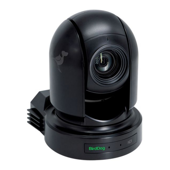
What’s in the Box? NOTE: The camera color may be white or black in colour depending on the item purchased. 1x BirdDog Eyes P200 1x IR Remote Controller (3V CR2032 Coin Lithium Battery Required) 1x Camera Power Adaptor & Power Cord... -
Page 11: Getting Started With Your P200
Getting Started With Your P200 If you are new to the world of NDI or BirdDog cameras, please follow this quick start guide to become familar with the basic setup of your new camera. You can view this as an online video:... -
Page 12: Basic Configuration
The Web UI BirdDog cameras have a web interface (Web UI) that is displayed by your computer brower and can be used to configure your camera remotely. Click on the gear icon on the bottom right of the Studio Monitor window. - Page 13 NDI connection info). In the example above, it is 59.94 fps. This frame rate should be set identically for all cameras according to the requirements of your production. Let’s see how to change the this and other important camera settings. A/V Settings Click on the A/V menu and select NDI AV SETUP.
-
Page 14: Network Configuration
NDI Audio Selection If you have a microphone plugged into the Audio In jack on the back of your camera, you can choose whether to embed the audio as part of the primary NDI channel, or have it on a separate NDI chan- nel for audio communication use. - Page 15 IP address. If you then use the camera in another application without a DHCP server, your camera will always default to the known fallover IP address. BirdDog Name You can give your camera a meaningful name to make identification easier when viewing NDI sources on a receiver such as a TriCaster, vMix or Studio Monitor.
-
Page 16: Camera Connections
Camera Connections 12VDCPowerPort Connect the supplied DC power adaptor and cord. USB 2.0 Port For firmware upgrade only. RS232 Control Port (RJ45) RJ45 to RS232 convertor cable is provided. Video Format Selector For video format selection. RS-422 Control Port (RJ45) RJ45 to RS422 convertor cable is provided. -
Page 17: Remote Controller
IR Remote Controller Sensors The sensors receive commands from infrared remote controller. Lens This is a 30X magnification optical zoom lens. Power LED Indicator The indicator displays green when the camera is connected to power outlet. When the power is turned on, it takes about 15 to 30 seconds to display the image after the LED displays. - Page 18 Camera ID (Total 3) Selector Preset Position (Total 6) Calling and Setting PAN-TILT Pan and Tilt direction control. • HOME: Home position, Resolution reset. • L/R Direction Set Left and right orientation setting. • ZOOM/FOCUS • Far - for objects further from the camera. •...
-
Page 19: Powering P200
IR Remote Controller ID Setting Set the IR SELECT switch on the back panel of the camera to 1, 2 or 3, to match the button on the con- troller that you wish to use. Powering P200 P200 can be powered by two ways. PoE+ (Power over Ethernet) PoE+ is a convenient way to power P200 as it allows both data and power to be sent through the same standard Ethernet cable. -
Page 20: Using The Camera Menus
Using the Camera Menus You can use the infrared remote controller to change camera settings while observing the menus dis- played on a connected computer screen. This section explains how to navigate the menus. The menu parameters may vary according to the different product model numbers. -
Page 21: Exposure Menu
Once you've navigated to a setting value, use the “←, →”buttons to increment or decrement the value. Press the MENU button to exit the menus. NOTE: When you are operating the menu using the infrared remote controller, you cannot set IR- RE- CEIVE in the SYSTEM menu to OFF. - Page 22 SHUTTER PRI: Shutter Priority mode. This mode allows you to set a fixed shutter SPEED with exposure achieved by automatic setting of IRIS, GAIN LIMIT, and EX-COMP. When you select one from various exposure modes, some of the following setting items that are required for the selected mode will be displayed.
-
Page 23: White Balance Menu
White Balance Menu The WHITE BALANCE menu allows you to choose from several white balance modes. WHITE BALANCE MENU EXPOSURE WB MODE AUTO WHITE BALANCE PICTURE 1 PICTURE 2 PAN TILT ZOOM SYSTEM WB MODE (White balance mode) Select the white balance mode from the following: AUTO: This mode computes the white balance value output using color information from the entire frame with a range of values from 2500K to 7500K. -
Page 24: Picture 1 Menu
OUTDOOR AUTO: This is an auto white balance mode specifically for outdoors. It allows you to capture images with natural white balance in morning and evening light. SL AUTO (Sodium Vapor Lamp Auto): This is an auto white balance mode that compensates for the orange light from sodium vapor lamps. -
Page 25: Picture 2 Menu
Picture 2 Menu PICTURE 2 MENU EXPOSURE CHROMA WHITE BALANCE HLC MODE PICTURE 1 BACKLIGHT COM. PICTURE 2 STABILIZER PAN TILT ZOOM STABLE ZOOM SYSTEM GAMMA CHROMA: You can set the brightness from OFF, LOW, MID, HIGH in each mode of the variable gamma mode. -
Page 26: Pan Tilt Zoom Menu
Pan Tilt Zoom Menu The Pan Tilt Zoom menu is used to select the pan/tilt/zoom mode. ZOOM RATIO OSD: Determines whether the zoom ratio displays on screen. AF SEN: When set to NORMAL, autofocus response will be fast and suited for frequently moving sub- jects. -
Page 27: System Menu
System Menu SYSTEM MENU EXPOSURE PELCO ID WHITE BALANCE IR-RECEIVE PICTURE 1 DISPLAY INFO PICTURE 2 PRESET MEMORY PAN TILT ZOOM FACTORY RESET SYSTEM RELOAD PRESET 1 AUTO FOCUS NORMAL FORMAT 1080p29.97 V0B1100S36[...] PELCO ID: When using RS485 (PELCO P/D) control, set Camera ID to the controlled address. This value is from 001-255. -
Page 28: Controlling The Camera Using The Remote Controller
Controlling the Camera Using the Remote Controller CAMERA SELECT L/R DIRECTION SET MENU HOME Panning and Tilting Press the POWER switch. The camera will turn on and perform the pan/tilt reset operation auto- matically. Press the arrow button to pan or tilt the camera. While checking the picture on the screen, press the desired arrow button. -
Page 29: Zooming
NOTE: The above setting only changes the signal emitted from the infrared remote controller, and does not change the setting of the camera itself. Therefore, repeat the setting for each infrared re- mote controller if you are using more than one infrared remote controller. When the STANDBY lamp is blinking If the camera is moved forcibly, for example, a finger or other object interferes with camera move- ment, the camera may fail to memorize the pan/tilt position. -
Page 30: Changing Resolution
Changing Resolution Press the RESOLUTION button. Use the arrow keys to navigate the displayed menu. Press Home to select. Screen will display ‘CHANGING…” Press Menu to exit. Storing the Camera Settings in Memory Using Presets Memory (Preset) Using the preset function, six sets of camera shooting conditions can be stored and recalled. The six sets of camera shooting conditions can be stored and recalled by using remote controller. - Page 31 The settings stored using this function are recalled when the power is turned on. Press the RESET button to reset the pan/tilt position. Adjust the position, zooming, focusing and backlighting of the camera. While holding down the PRESET button, press any of the POSITION buttons, 1 to 6, in which you want to store the settings.
-
Page 32: Operating Multiple Cameras With The Infrared Remote Controller
Operating Multiple Cameras with the Infrared Remote Controller MENU POWER CAMERA SELECT CAMERA SELECT Set the DIP switch on the base of the camera to the number of camera you want to operate - 1, 2 or 3. DIP switch setting instructions are printed on the camera base. Press the CAMERA SELECT button on the infrared remote controller that corresponds to the num- ber set in step. -
Page 33: Ndi Set Up
In order to access the Web UI on a network which is configured to a different subnet, change your computers IP address to match the BirdDog unit. Once you gain access to the Web UI, choose your IP address to match the rest of the devices on your network. -
Page 34: Password Management
Enter Password Default Password The Web UI is secured by a user-selectable password. The default password is: birddog (one word, lower case). Password Reset To change the password simply login using the default password, navigate to the network tab in the web interface, and select change password. -
Page 35: Ndi Av Set Up
NDI AV Set Up Bitrate Management Birddog Devices allow you to set your target NDI output bitrate. This allows you to select a compres- sion ratio that is more efficient for your networking infrastructure (lower bandwidth) or higher image quality for critical footage. The scale allows you to select the range of 60Mbps - 360Mbps. -
Page 36: Ndi Group Enable
BirdDog Comms application you can then use the P200 as an output for IFB communications. Failover Source P200 can inform any receiving device of a failover scheme. This means if their BirdDog NDI stream is interrupted for any reason the receiver can automatically switch to a pre-determined alternative NDI stream. -
Page 37: Ip Address Configuration
We do recommend that you keep the birddog prefix as some devices and soft- ware will look for the birddog name. The name can be any combination of a-z, 1-0, and '–‘. A name such as birddog-cam1 will work well. -
Page 38: Ptz Set Up
PTZ Set Up Control You are able to save and recall presets from the Dashboard using the Select Preset option. Simply press the Preset number you wish to recall or save followed by APPLY or SAVE. PT Max Speed When controlling P200 over NDI you can limit the maximum speed of PTZ movements by affecting this option, the higher the number (18) the faster and more sensitive the movements will be on the camera. -
Page 39: Ndi Network Settings
Utilising Muliticast offloads the distribution of the NDI A/V packets from the BirdDog Flex 4K to the network infrastructure. You should take care to ensure your network is spe- cifically configured to support Multicast as using it on an ill-prepared network can create unintended... -
Page 40: Multitcp
MultiTCP MultiTCP is a new NDI transport method that allows users to send NDI video over poor network to- pography such as WAN (Wide Area Networks) without experiencing issues such as packet loss and lost frames. In the past in order to send NDI video over a WAN the UDP transport was the only option available. -
Page 41: Colour Matrix
Colour Matrix The Colour matrix section allow you to fine-tune the cameras performance for individual colours across the spectrum. You can see in this figure that the color spectrum is divided into six sections, theses being Red, Green, Blue, Cyan, Magenta and Yellow. The Colour Matrix control allows individual fine-tuning of each of these colour sections without affect- ing the response of other colour components. -
Page 42: Using A Colour Chart
negative hue transition point red colour point P200 Colour Matrix controls allow you to adjust the colour offset in a negative (counter clockwise) or positive (clockwise) direction, effectively moving the cameras response to any colour towards its neighbouring colour transition point. Adjusting individual colour Hue can assist dramatically in matching colour representation from the camera to true-to like colours or matching P200 to other cameras in your production. -
Page 43: Image Enhancement
Image Enhancement The image enhancement properties allow for adjustments and fine control of the cameras perfor- mance including video enhancement, detail enhancement and exposure enhancement. Enabling video enhancement will attempt to adjust the amount of detail and gain for both the shadows and highlights of the image. -
Page 44: Detail Enhancement
Detail Enhancement The Detail Enhancement section adjusts the definition of edges in the image and overall image sharp- ness. Exposure Enhancement Gamma offset adjusts the way the camera will handle the relationship between dark and light areas across the overall image. This can be represented as a positive or negative number. A negative or lower number places more bias towards the shadows giving more detail to the darker areas of the image. -
Page 45: Receiving Ndi Video
Receiving NDI Video There are many applications that support receiving the NDI signal that P200 produces. Each applica- tion will vary slightly on how you choose your source. NewTek Studio Monitor NDI® Tools is a free suite of applications designed to introduce you to the world of IP video and is avail- able here. - Page 46 IP Video Signal The camera can simultaneously stream NDI® video output and SDI video output and HDMI video out- put. Connect the camera to the network using Cat5/Cat6 network cable. You need to have a web browser for product configuration. PELCO address and Baud Rate setting on the camera must be as same as the setting on camera IP WEB interface.
-
Page 47: Camera Control
The easiest way to control your camera is via the BirdDog PTZ Keyboard! BirdDog PTZ Keyboard is a full featured PTZ Keyboard that supports NDI®, NDI|HX, Visca over IP, RS422, and RS232. By harnessing BirdDog’s next generation NDI® and IP technology, it’s never been easier to discover, connect, and control your PTZ cameras. -
Page 48: Controlling Your Camera Via Other Protocols
Controlling Your Camera Via Other Protocols P200 also supports control via VISCA-over-IP, RS-232 and RS-422/485. This section details how to configure control under these protocols. When the camera is connected to a computer and joystick keyboard with a VISCA cable (cross type, RS-232), you can operate the camera with the computer and the joystick keyboard. -
Page 49: Visca Over Ip Control
VISCA over IP Control With VISCA over IP, you can control the camera using the VISCA protocol on a controller equipped with IP communication capabilities via LAN. HDMI Video Signal 3G-SDI Video Signal PoE Power VISCA Over IP Control VISCA over IP communication specifications: Interface: RJ-45 10/100/1000 Mbps •... - Page 50 DIP Switch Settings The DIP switches are for setting the camera configuration for following items. The Camera ID address and video resolution settings (below) can be also be set via the camera OSD menu. The camera can be set either using the OSD menu or DIP switches. They override each other - after the camera is turned on, the most recent setting is used.
- Page 51 The Rear Panel Rotary DIP Switch The rotary DIP switch selects the video format. Use small screw driver to turn the switch to the desired number or letter.
-
Page 52: Using Rs-232 (Visca)
Using RS-232 (VISCA) You can use the RS-232 port to connect to optional controllers, such as joystick control keyboard, con- trol PC station, to operate the camera. To perform pan/tilt and zoom operations using the joystick of the control keyboard, and to perform the Preset operation using the control buttons. - Page 53 RS-232 Win. DB-9 RS-232 Camera or RS-232 Win. DB-25 Mini DIN 1. DTR 1. CD 8 pin serial 1. DTR 1. FG 2. DSR 2. RXD 1. DTR 1. DTR 2. DSR 2. TXD 3. TXD 3. TXD 2. DSR 2.
- Page 54 Use the included RJ45 to RS422/232 extension cables with a Phoenix terminal contact adaptor to make RS232 connection for your control device. RS232 Serial Port RS232 RS232 1. GND 1. GND connection on 2. RXD 2. RXD controller side 3. TXD 3.
- Page 55 Making a RS232 Daisy Chain multiple camera connection with standard RS232 serial port controller: VCC - CC45232 (Orange/White) 1. DSR (Orange) 2. DTR (Green/White) 3. RXD (Blue) 4. GND (Blue/White) 5. TXD (Green) 6. NC (Brown/White) 7. NC RJ45 TO RS232 (Brown) 8.
-
Page 56: Using Rs422(Visca) / Rs485 (Pelco P/D)
Using RS422(VISCA) / RS485 (PELCO P/D) You can use RS422/485 port connect to optional controllers, such as joystick control keyboard, control PC station, to operate the camera. To perform pan/tilt and zoom operations using the joystick of the control keyboard, and to perform the Preset operation using the control buttons. - Page 57 The connection of a SONY keyboard is different than other VISCA (Non-Sony) keyboards. If using a SONY controller and Daisy Chaining multiple cameras via RS422 connection: SONY Keyboard RS422 Connection SONY Keyboard RS422 (VISCA) Daisy Chain Connection Multiple Cameras Connection (SONY Keyboard) KEYBOARD Keyboard...
- Page 58 Use the included RJ45 to RS422 extension cable with a Phoenix connecter adaptor to make RS422 connection for your control device. RS422 Serial Port connection on controller side 5. R – Multicore 4. R + 3. T – Control VCC-CC45RS 2.
-
Page 59: Pelco P/D Keyboard Rs485 Connection
You can make a RS422 Daisy Chain multiple camera connection with RS422 standard serial port controller. 5. R – 4. R + 3. T – VCC-CC45RS 2. T + RJ45 TO RS422/485 1. GND CONTROL CABLE ADAPTOR RS422 5. R – 4. - Page 60 PELCO RS485 Connection RS485 RS422 (VISCA) Daisy Chain PELCO P/D Keyboard Multiple Cameras Connection Connection (VISCA Keyboard) KEYBOARD Keyboard Camera 1. TDX IN –2 . TDX IN + 6. RS485 + 1. TXD IN – CAM 1 7. RS485 – 2.
- Page 61 Use a CAT5/6 T-568B Standard Ethernet cable direct connect between the camera and the con- troller to make RS485 connection by following the pin definition below. CAT5/6 1. RX – (Orange/White) Network Cable 2. RX + (Orange) 3. GND (Green/White) RS485 4.
-
Page 62: Operating Multiple Cameras Using Rs-232 And 422/485
Operating Multiple Cameras using RS-232 and 422/485 Using RS-232 (VISCA), you can connect to 7 cameras. Using RS-422 (VISCA), you can connect to 7 cameras. • Using RS-485 (PELCO), you can connect to 255 cameras. • Using RS-485 (PELCO), all camera addresses must be set up before the connection. You •... -
Page 63: Glossary
Glossary Domain A domain contains a group of computers that can be accessed and administered with a common set of rules. Domain can also refer to the IP address of a website on the Internet. DNS (Domain Name System) is a system used by the Internet and private networks to translate domain names into IP addresses. - Page 64 PELCO PELCO is a camera control protocol used with PTZ cameras. See also VISCA. Power over Ethernet Port A port is a communications channel for data transmission to and from a computer on a network. Each port is identified by a 16-bit number between 0 and 65535, with each process, application, or service using a specific port (or multiple ports) for data transmission.
- Page 65 WELCOME TO THE FUTURE.
- Page 66 bird-dog.tv hello@bi rd-dog.tv...
Need help?
Do you have a question about the NDI P200 and is the answer not in the manual?
Questions and answers