
Related Manuals for Kramer VP-554X


Summary of Contents for Kramer VP-554X
- Page 1 USER MANUAL MODEL: VP-554X Presentation Switcher/Scaler P/N: 2900-301360 Rev 1 www.kramerAV.com...
-
Page 2: Table Of Contents
Mounting VP-554X Connecting VP-554X Connecting the Output to a Balanced/Unbalanced Stereo Audio Acceptor Connecting a Balanced/Unbalanced Stereo Audio Source to the Input Connecting to VP-554X via RS-232 Wiring RJ-45 Connectors Operating and Controlling VP-554X Routing an input to an output... -
Page 3: Introduction
Kramer Electronics Ltd. Introduction Welcome to Kramer Electronics! Since 1981, Kramer Electronics has been providing a world of unique, creative, and affordable solutions to the vast range of problems that confront the video, audio, presentation, and broadcasting professional on a daily basis. In recent years, we... -
Page 4: Overview
European Advanced Recycling Network (EARN) and will cover any costs of treatment, recycling and recovery of waste Kramer Electronics branded equipment on arrival at the EARN facility. For details of Kramer’s recycling arrangements in your particular country go to our recycling pages at www.kramerav.com/support/recycling. - Page 5 Scaled video outputs – 4 pairs of mirrored HDMI and HDBT outputs. • Embedded audio on the HDMI and HDBT inputs and outputs. • One stereo speaker output, 20W per channel into 4Ω, on a 4-pin terminal block connector. VP-554X – Introduction...
-
Page 6: Typical Applications
• Any application where high quality conversion and switching of multiple and different video signals to graphical data signals is required for display or projection purposes. Controlling your VP-554X Control your VP-554X directly via the front panel push buttons (with on-screen menus), or: •... -
Page 7: Defining Vp-554X Presentation Switcher/Scaler
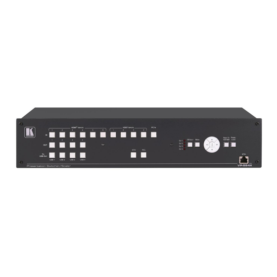
Kramer Electronics Ltd. Defining VP-554X Presentation Switcher/Scaler This section defines VP-554X. Figure 1: VP-554X Presentation Switcher/Scaler Front Panel Feature Function To USB OUT Buttons Press a USB button to switch a USB input (1 to 4) to the USB output. - Page 8 Kramer Electronics Ltd. Figure 2: VP-554X Presentation Switcher/Scaler Rear Panel Feature Function VIDEO OUTPUT IR (Rx, Tx) left 2-pins on Connect to the IR connector of an HDBT input (Tx Connectors a 5-pin Terminal Block to Rx and Rx to Tx), to tunnel IR data between an...
- Page 9 MONITOR OUT 5-pin Terminal Block Connect to a stereo balanced audio acceptor (for Connector example, active speakers or an audio power amplifier). SPEAKER OUT 4-pin Terminal Block Connect to a pair of loudspeakers. Connector VP-554X – Defining VP-554X Presentation Switcher/Scaler...
-
Page 10: Mounting Vp-554X
Kramer Electronics Ltd. Mounting VP-554X This section provides instructions for mounting VP-554X. Before installing, verify that the environment is within the recommended range: • Operation temperature – 0 to 40C (32 to 104F). • Storage temperature – -40 to +70C (-40 to +158F). -
Page 11: Connecting Vp-554X
Kramer Electronics Ltd. Connecting VP-554X Always switch off the power to each device before connecting it to your VP-554X. After connecting your VP-554X, connect its power and then switch on the power to each device. Figure 3: Connecting to the VP-554X Rear Panel... -
Page 12: Connecting The Output To A Balanced/Unbalanced Stereo Audio Acceptor
8. Connect the: ▪ RS-232 EXT CONTROL 3-pin terminal block connector port to an RS-232 controlled device to control it via commands sent from the VP-554X. ▪ RS-232 CONTROL 3-pin terminal block connector port to a PC to control the unit. -
Page 13: Connecting A Balanced/Unbalanced Stereo Audio Source To The Input
Figure 6: Connecting a Balanced Stereo Audio Figure 7: Connecting an Unbalanced Stereo Audio Source to the Balanced Input Source to the Balanced Input Connecting to VP-554X via RS-232 You can connect to VP-554X via an RS-232 connection using, for example, a PC. -
Page 14: Operating And Controlling Vp-554X
Storing the Current Configuration To store the current configuration: 1. Set the required device configuration. 2. Press and hold STO until button flashes once. The current configuration is stored. VP-554X – Operating and Controlling VP-554X... -
Page 15: Resetting The Resolution
1. On the front panel button, press OSD SELECT to cycle through the outputs, to select the output to control via OSD (the OSD output). The LED lights next to the selected output. 2. Press MENU. VP-554X – Operating and Controlling VP-554X... - Page 16 Defining Daily Reset Time on page 25. • Setting the HDBT Input Range on page 26. • Viewing Device Information on page 26. • Performing a Reset on page 26. • Defining Network Parameters on page 26. VP-554X – Operating and Controlling VP-554X...
- Page 17 OSD output via the OSD MENU buttons. The resolution is set only for the output that is selected (via the front panel OSD SELECT button) to show the OSD. VP-554X – Operating and Controlling VP-554X...
- Page 18 To set the no-signal screen color: 1. On the front panel press MENU. The menu appears. 2. Select VIDEO, then select FREEZE. 3. Press ENTER and select ON or OFF. 4. Press ENTER. The screen freeze state is set. VP-554X – Operating and Controlling VP-554X...
- Page 19 VP-554X enables adjusting the selected OSD output image parameters such as contrast, brightness and so on. To adjust the image parameters: 1. On the front panel press MENU. The menu appears. 2. Click PICTURE. VP-554X – Operating and Controlling VP-554X...
- Page 20 0 to 100 (Default: 80). HDMI HARDSTOP Set HDMI volume hard stop. 0~100 (Default: 80). (Use this feature to limit the maximum HDMI output volume level). LINE HARDSTOP Set the analog audio hard stop. VP-554X – Operating and Controlling VP-554X...
- Page 21 Set the Audio equalization: EQ 120Hz, 200Hz, 500Hz, 1200Hz, 3000Hz, 7500Hz, 12000Hz or reset to default value. RESET AUDIO Select to reset all the audio parameters to their default values. 5. Press ENTER. Audio parameters are defined. Talkover Mode Figure 8: Talkover Mode VP-554X – Operating and Controlling VP-554X...
- Page 22 (for a short period of time). Release Time Set the release time to define the transition time for the audio level to return from its reduced level to its normal level after the Hold Time period. VP-554X – Operating and Controlling VP-554X...
- Page 23 Microphone settings are defined. Defining USB Settings The VP-554X incorporates a simple, yet effective, 4:1 USB switcher. The switcher can be used, for example, to connect one out of several PCs to a smart board or other USB client. The USB switcher can be routed as a separate layer, or can be tied to the video switching layer of the unit.
- Page 24 Info (default) – Information appears for 10 seconds. On – Information appears constantly. Off – Information does not appear. RESET OSD Select to reset the OSD parameters to their default values. OSD parameters are set. VP-554X – Operating and Controlling VP-554X...
- Page 25 Disable outputs after ~ 10 seconds of no input detection. SLOW (120s) Disable outputs after ~ 2 minutes of no input detection. IMMEDIATE Disable outputs immediately when there is no input detection. 4. Press ENTER. Sleep mode is defined. VP-554X – Operating and Controlling VP-554X...
- Page 26 4. Press ENTER. VP-554X is set to video wall mode. Managing EDID via OSD VP-554X enables managing the EDID via the OSD menu buttons. The EDID menu appears in the OSD output 1 menu only. VP-554X – Operating and Controlling VP-554X...
- Page 27 1. On the front panel press MENU. The menu appears. 2. Click ADVANCED and select DAILY RESET. 3. Click ENTER. 4. Select ON to enable a daily reset. 5. Set the hours (24) and minutes (60). VP-554X – Operating and Controlling VP-554X...
- Page 28 Wait for completion of factory reset (resolution is set to Native). Device is reset. Defining Network Parameters Define the Network parameters via the OSD menu. The ETHERNET menu appears in OSD output 1 menu only. VP-554X – Operating and Controlling VP-554X...
-
Page 29: Operating Via Ethernet
3. Highlight the network adapter you want to use to connect to the device and click Change settings of this connection. The Local Area Connection Properties window for the selected network adapter appears as shown in Figure VP-554X – Operating and Controlling VP-554X... - Page 30 (TCP/IPv4) depending on the requirements of your IT system. 5. Click Properties. The Internet Protocol Properties window relevant to your IT system appears as shown in Figure 10 Figure Figure 10: Internet Protocol Version 4 Properties Window VP-554X – Operating and Controlling VP-554X...
- Page 31 You can connect the Ethernet port of VP-554X to the Ethernet port on a network hub or using a straight-through cable with RJ-45 connectors. Configuring Ethernet Port You can set the Ethernet parameters via the embedded Web pages. VP-554X – Operating and Controlling VP-554X...
-
Page 32: Using Embedded Web Pages
Operating via Ethernet on page 27). • Ensure that your browser is supported. The following operating systems and Web browsers are supported: Operating Systems Browser Firefox Windows 7 Chrome Safari Edge Windows 10 Firefox Chrome Safari Safari Android VP-554X – Using Embedded Web pages... - Page 33 Kramer Electronics Ltd. To browse the VP-554X web pages: 1. Open your Internet browser. 2. Type the IP address of the device in the address bar of your browser. For example, the default IP address: The Authentication window appears (if set, security is enabled): Figure 13: Using the Embedded Web pages –...
-
Page 34: Switching And Setting Ports
Switching an Input to an Output on page 35. • Using VP-554X with a “Step-in” Device on page 37. Viewing and Adjusting Output Settings You can view the status of the outputs and adjust their settings via the output buttons. - Page 35 1. In the Navigation pane, click Switching. The Switching page appears (Figure 14). 2. Click on the audio out button to open the Audio Out settings window. Figure 17: Audio Output Settings 3. Change the output label (up to 16 characters) name and click VP-554X – Using Embedded Web pages...
- Page 36 ▪ Click after selecting an output to switch the audio only to the selected output. Input settings are viewed and adjusted. Defining Video Input Settings Define the HDMI and HDBT input settings. VP-554X – Using Embedded Web pages...
- Page 37 (Figure 15). The Output button’s color changes from black to purple. 3. Click any of the following buttons on the selected input button: ▪ to switch the video signal only to the selected output. VP-554X – Using Embedded Web pages...
- Page 38 Kramer Electronics Ltd. ▪ to switch the video and audio signals to the selected output. ▪ to switch the audio signal only to the selected output. The input signal is switched to the selected output. VP-554X – Using Embedded Web pages...
- Page 39 Kramer Electronics Ltd. Using VP-554X with a “Step-in” Device Remotely manage a Step-In device (for example, Kramer DIP-31) that is connected to VP-554X. In this example, Kramer DIP-31 is connected to the HDMI IN 2. To control another device remotely: 1.
- Page 40 HDMI IN2 input button. Step-in switching window appears. Figure 22: Step-in Switching Window 6. Click an Out button and then a DIP-31 input button. The selected input is switched to the selected output. The connected remote device is controlled. VP-554X – Using Embedded Web pages...
-
Page 41: Adjusting The Output Image
Setting Output Resolution on page 15). 7. Define Auto Sync Off setup (Disable, Fast, Slow or Immediate). 8. Select the color of the output image when no signal is present (Black, White, Blue, Red or Green). VP-554X – Using Embedded Web pages... - Page 42 Audio is muted upon video Freeze state. ▪ Audio is muted upon video Blank state ▪ Audio is muted both when image is in the Blank or Freeze state. ▪ Mute feature us OFF. Output image is defined. VP-554X – Using Embedded Web pages...
-
Page 43: Changing Device Settings And Upgrading Firmware
2. Uncheck the DHCP check box to change any of the parameters (IP Address, Netmask and/or Gateway). Parameters can be edited. 3. Edit IP Address, Netmask and/or Gateway Parameters and click Save Changes. Ethernet Changes saved. VP-554X – Using Embedded Web pages... -
Page 44: Routing The Usb Switcher
1, the USB input that is tied to it switches to the USB output at the same time. This section enables performing the following actions: • Tying a USB Input to a Video Input on page 43. • Routing the USB Switcher on page 43. VP-554X – Using Embedded Web pages... - Page 45 Click a USB button (from 1 to 4). The USB input is routed to the USB output. ▪ Check that USB inputs are tied properly to the video inputs and click Tie to Input. The USB inputs are switched to the USB output. VP-554X – Using Embedded Web pages...
-
Page 46: Defining Audio Parameters
1. In the Navigation pane, click Audio Settings. The Audio Settings page appears (Figure 28). 2. Next to Microphone open the drop-down box to set the operation mode (DYNAMIC, CONDENSER). Microphone operation mode is defined. VP-554X – Using Embedded Web pages... - Page 47 1. In the Navigation pane, click Audio Settings. The Inputs tab in the Audio Settings page appears (Figure 28). 2. Select an Output tab (for example, Output 1). Figure 29: Audio Settings Page – Setting the Audio Outputs VP-554X – Using Embedded Web pages...
- Page 48 (Automatic, Embedded or Analog), see Setting Audio Parameters on page 18. ▪ Prepare audio Mapping for each audio input to be switched (see Setting Audio Parameters on page 18). Audio Out parameters are defined. VP-554X – Using Embedded Web pages...
- Page 49 Audio output includes the Monitor and Speakers outputs. ▪ Set the SPEAKER volume and hard-stop levels. ▪ Click under SPEAKER Vol to mute the HDMI audio signal. ▪ Set the LINE (monitor output) volume and hard-stop levels. VP-554X – Using Embedded Web pages...
- Page 50 3. Next to MIC Gain (1 and 2), enter the gain value or use the sliders to set the value. 4. Select an audio output for setting the microphone mix. 5. Set the microphone operation mode to Mixer, Talk Over or Off for each output. VP-554X – Using Embedded Web pages...
-
Page 51: Managing Edid
The selected EDID can be copied to the selected input/s. To copy an EDID from the default, output or user EDID: 1. In the Navigation pane, click Device Settings. The EDID page appears. Figure 32: EDID Page – Selecting an EDID Source VP-554X – Using Embedded Web pages... - Page 52 When an HDMI/HDBT EDID is selected as the source, only the HDMI/HDBT inputs are selected. Figure 33: EDID Page – Reading an Input EDID 4. Click COPY. The selected EDID is copied to the selected inputs. VP-554X – Using Embedded Web pages...
-
Page 53: Setting Ethernet Data Routing
1. In the Navigation pane, click Data Routing. The Data Routing page appears. Figure 34: Data Routing Page 2. For each HDBT port, set the data parameters (see Setting the HDBT Port Data Routing Parameters on page 52). VP-554X – Using Embedded Web pages... - Page 54 Baud Rate: 4800, 9600, 19200, 38400, 57600 or 115200. ▪ Data Bits: 5, 6, 7 or 8. ▪ Parity: NONE, ODD or EVEN. ▪ Stop Bits: 1 or 2. ▪ Flow Control: OFF or ON. ▪ Protocol: TCP or UDP. VP-554X – Using Embedded Web pages...
-
Page 55: Setting Up For Rs-232 External Device Control
For example, when connecting the Kramer TP-580Txr to an HDBT port on the VP-554X, you need to set the Data Channel to 4 to pass RS-232 data through that HDBT port. Setting up for RS-232 External Device Control You can set... - Page 56 Change any of the command configurations. ▪ Enable or disable the command. 6. Add as many commands as needed. RS-232 commands are configured and can be sent to an external device that is connected to the selected output. VP-554X – Using Embedded Web pages...
-
Page 57: Configuring A Video Wall
1. In the Navigation pane, click Video Wall. The Video Wall page appears. Figure 39: Video Wall Page 2. Click On to enable the video wall or click Off (default) to disable. 3. Select the Video Source from the drop-down list (HDMI, HDBT or PC inputs). VP-554X – Using Embedded Web pages... - Page 58 Output 2 is assigned Window 2. To switch the outputs in those windows, click window 3 and then Window 2. The outputs switch. Figure 40: Switching Window Outputs 5. Set the Bezel for each window. Video wall is configured. VP-554X – Using Embedded Web pages...
-
Page 59: Viewing System Diagnostics
1. In the Navigation pane, click System Status. The System Status page appears. Figure 41: Advanced Page – System Status 2. In the System Status area, view the system lifetime and current runtime (in hours), power supply and temperature indicators. System status is observed. VP-554X – Using Embedded Web pages... -
Page 60: Setting Webpage Access
59. • Disabling Authentication on page 60. Changing the Password To change the password: 1. In the Navigation pane, click Authentication. The Authentication page appears. Figure 42: Authentication Page 2. Enter the new password. VP-554X – Using Embedded Web pages... - Page 61 1. In the Navigation pane, click Authentication. The Authentication page appears (see Figure 42). 2. Check Authenticate Web pages Access. Figure 44: Authentication Page – Password Authentication 3. Click Set changes. The following message appears. Figure 45: Message 4. Click OK. Authentication is enabled. VP-554X – Using Embedded Web pages...
-
Page 62: Setting Timeout
1. In the Navigation pane, click Advanced Setting. The Advanced Setting page appears. Figure 47: Advanced Setting page 2. Set the delay time 0-9999 seconds (where 0 is no timeout) and click SET. Timeout is set. VP-554X – Using Embedded Web pages... -
Page 63: Viewing About Page
Kramer Electronics Ltd. Viewing About Page VP-554X About Us page lets you view the web page version and Kramer Electronics Ltd details. Figure 48: About Page VP-554X – Using Embedded Web pages... -
Page 64: Technical Specifications
4 100BaseT Ethernet On RJ-45 female connectors for device control and LAN extension Video Max Resolution HDMI: 4K60 4:4:4 HDBT: 4K60 4:2:0 PC (VGA):1080p Compliance Up to HDMI 2.0 and HDCP 2.2 Extended Ethernet Max Transmission Bandwidth 100Mbps VP-554X – Technical Specifications... - Page 65 6.3kg (13.9lbs) approx. Accessories Included Power adapter cord Optional For optimum range and performance use the recommended USB, Ethernet, serial and IR Kramer cables available at www.kramerav.com/product/VP-554X Specifications are subject to change without notice at www.kramerav.com VP-554X – Technical Specifications...
-
Page 66: Default Communication Parameters
Native/preferred timing.. 3840x2160p at 60Hz (16:9) Modeline...."3840x2160" 594.000 3840 4016 4104 4400 2160 2168 2178 2250 +hsync +vsync Detailed timing #1..1920x1200p at 60Hz (16:10) Modeline...."1920x1200" 154.000 1920 1968 2000 2080 1200 1203 1209 1235 +hsync -vsync VP-554X – Technical Specifications... - Page 67 Supports dual-link DVI... No Maximum TMDS clock..300MHz Audio/video latency (p).. n/a Audio/video latency (i).. n/a HDMI video capabilities.. Yes EDID screen size..No additional info 3D formats supported..Not supported Data payload..... 030C001000B83C2F006001030400000000000000000000 CE vendor specific data (VSDB) VP-554X – Technical Specifications...
- Page 68 Maximum TMDS clock..15MHz YCbCr 4:2:0 capability map data Data payload..... 0F0012 Report information Date generated... 6/28/2022 Software revision..2.91.0.1043 Data source....Real-time 0x0031 Operating system..10.0.19044.2 Raw data 00,FF,FF,FF,FF,FF,FF,00,2D,B2,54,05,01,00,00,00,14,1E,01,03,80,1F,11,78,0A,1E,AC,98,59,56,85,28, 29,52,57,A5,4B,00,81,C0,81,80,A9,C0,A9,40,D1,C0,71,4F,D1,00,81,00,08,E8,00,30,F2,70,5A,80,B0,58, 8A,00,A0,5A,00,00,00,1E,28,3C,80,A0,70,B0,23,40,30,20,36,00,A0,64,00,00,00,1A,00,00,00,FC,00,56, 50,2D,35,35,34,58,0A,20,20,20,20,20,00,00,00,FD,00,17,3D,0F,88,3C,00,0A,20,20,20,20,20,20,01,9F, 02,03,41,F0,50,10,05,20,22,04,03,12,13,14,61,5D,5F,66,62,64,1F,23,0F,07,07,83,4F,00,00,77,03,0C, 00,10,00,B8,3C,2F,00,60,01,03,04,00,00,00,00,00,00,00,00,00,00,67,D8,5D,C4,01,78,80,03,E3,0F,00, 12,02,3A,80,18,71,38,2D,40,58,2C,45,00,A0,5A,00,00,00,1E,56,5E,00,A0,A0,A0,29,50,30,20,35,00,A0, 5A,00,00,00,1A,00,00,00,00,00,00,00,00,00,00,00,00,00,00,00,00,00,00,00,00,00,00,00,00,00,00,77 VP-554X – Technical Specifications...
-
Page 69: Protocol 3000
Kramer Electronics Ltd. Protocol 3000 Kramer devices can be operated using Kramer Protocol 3000 commands sent via serial or Ethernet ports. Understanding Protocol 3000 Protocol 3000 commands are a sequence of ASCII letters, structured according to the following. • Command format:... -
Page 70: Protocol 3000 Commands
7 – Output4 HDMI 8 – Output4 LINE 9 – Audio Out Speaker 10 – Audio Out Line – Volume level 0 to 100 vol_level ++ (increase current value by 1dB); -- (decrease current value by 1dB) VP-554X – Protocol 3000... - Page 71 0x100 – HDBT3 0x200 – HDBT4 safe_mode – Safe mode 0 – device accepts the EDID as is without trying to adjust 1 – device tries to adjust the EDID (default value if no parameter is sent) VP-554X – Protocol 3000...
- Page 72 0-(2^16-1). – TCP/UDP port_type ETH-PORT? Get Ethernet port COMMAND Get the Ethernet port – TCP/UDP port number: protocol. port_id protocol for UDP: #ETH-PORT?port_type<CR> UDP – 50000 to 50999 #ETH-PORT?udp<CR> FEEDBACK TCP – 5000 to 5099 ~nn@ETH-PORTport_type,port_id<CR><LF> VP-554X – Protocol 3000...
- Page 73 0 – Off then HDCP is defined as not supported. If 1 – On OUT 1 is not For Outputs (1) connected, then HDCP 2 – Follow In is defined by OUT 2. 3 – Follow Out VP-554X – Protocol 3000...
- Page 74 4 – Output4 video_mode – Status 0 – Over Scan 1 – Full 2 – Best Fit 3 – Pan Scan 4 – Letter Box 5 – Under 2 6 – Under 1 7 – Follow In VP-554X – Protocol 3000...
- Page 75 1 – Trigger 2 – Attack time 3 – Hold time 4 – Release time – MIC_INDEX value (in value corresponding to MIC_INDEX units) For Depth:0~100 For Trigger:0~100(-60~40dB) For Attack time:0~200(0~20.0) For Hold time:0~200(0~20.0) For Release time:0~200(0~20.0) VP-554X – Protocol 3000...
- Page 76 4 – Output2 LINE 5 – Output3 HDMI 6 – Output3 LINE 7 – Output4 HDMI 8 – Output4 LINE 9 – Audio Out Speaker 10 – Audio Out Line – On/Off mute_mode 0 – Off 1 – On VP-554X – Protocol 3000...
- Page 77 Internet. Be aware of security problems. ip_address – Format: NET-IP Set IP address. COMMAND Set the IP address to #NET-IPip_address<CR> xxx.xxx.xxx.xxx 192.168.1.39: For proper settings #NET- FEEDBACK consult your network IP192.168.001.039<CR ~nn@NET-IPip_address<CR><LF> administrator. > VP-554X – Protocol 3000...
- Page 78 – 1 preset PRST-RCL Recall saved preset list. COMMAND Recall preset: #PRST-RCLpreset<CR> #PRST-RCL1<CR> In most units, video FEEDBACK and audio presets with ~nn@PRST-RCLpreset<CR><LF> the same number are stored and recalled together by commands #PRST-STO and #PRST-RCL. VP-554X – Protocol 3000...
- Page 79 1 to On: #SCLR-PCAUTOscaler_index,auto_scan<CR> #SCLR-PCAUTO1,1<CR> 2 – Output2 FEEDBACK Trigger the Auto 3 – Output3 ~nn@SCLR-PCAUTOscaler_index,auto_scan<CR><LF> Adjust feature of PC 4 – Output4 input. auto_scan – 0 – Off 1 – On 3 – Immediate VP-554X – Protocol 3000...
- Page 80 0 – Off 1 – Mixer 2 – Talkover firmware_version – VERSION? Get firmware version COMMAND Get the device firmware #VERSION?<CR> number. version number: XX.XX.XXXX where the digit groups #VERSION?<CR> are: major.minor.build version FEEDBACK ~nn@VERSIONfirmware_version<CR><LF> VP-554X – Protocol 3000...
- Page 81 6=1280x1024@60Hz 7=1360x768@60Hz 8=1400x1050@60Hz 9=1440x900@60Hz 10=1600x1200@60Hz 11=1680x1050@60Hz 12=1920x1200@60Hz RB 13=2560x1600@60Hz RB 14=1920x1080@60Hz 15=1280x720@60Hz 16=2048x1080@50Hz 17=2048x1080@60Hz 18=2560x1440@60Hz RB 19=3440x1440@30Hz RB 20=3440x1440@60Hz RB 21=720x480p@60Hz 22=1280x720p@60Hz 23=1920x1080p@60Hz 24=720x576p@50Hz 25=1280x720p@50Hz 26=1920x1080p@50Hz 27=1920x1080p@24Hz 28=1920x1080p@25Hz 29=1920x1080p@30Hz 30=2560x1080p@50Hz 31=2560x1080p@60Hz 32=3840x2160p@24Hz 33=3840x2160p@25Hz 34=3840x2160p@30Hz 35=3840x2160p@50Hz 36=3840x2160p@60Hz VP-554X – Protocol 3000...
- Page 82 1 for Speaker Output ▪ – Signal ID <signal_type> attribute: o AUDIO ▪ – Indicates a specific <index> channel number when there are multiple channels of the same type: 1 – Audio level audio_level 0 to 100 VP-554X – Protocol 3000...
- Page 83 VIDEO is interpreted as: o AUDIO ▪ <index> – Indicates a specific ROUTEout.sdi.5.v channel number when there ideo.1,in.sdi.1.v are multiple channels of the ideo.1<CR> same type This is an Extended Protocol 3000 command. VP-554X – Protocol 3000...
- Page 84 0:no (7~10):(1~4) 7:1 HDBT1 : step in only for step in devices with HDBT out change(VP- device input 1 Set VP-554X video source+ step in video source 554X video 8:2 HDBT2 : step in source device input 2 unchange )
- Page 85 Set video+audio source + aduio setting ( 2:Output2 1:2:HDMI1 Analog embeded or Analog ) 3:Output3 2:1:HDMI2 Embedded 4:Output4 2:2:HDMI2 Analog 3:1:HDMI3 Embedded 3:2:HDMI3 Analog 4:1:HDMI4 Embedded 4:2:HDMI4 Analog 5:1:HDMI5 Embedded 5:2:HDMI5 Analog 6:1:HDMI6 Embedded 6:2:HDMI6 Analog VP-554X – Protocol 3000...
- Page 86 Set video+audio source + audio setting ( 1:2:HDMI1 Analog Embedded or Analog ) + USB port " tie to input ". 2:1:HDMI2 Embedded 2:2:HDMI2 Analog 3:1:HDMI3 Embedded 3:2:HDMI3 Analog 4:1:HDMI4 Embedded 4:2:HDMI4 Analog 5:1:HDMI5 Embedded 5:2:HDMI5 Analog 6:1:HDMI6 Embedded 6:2:HDMI6 Analog VP-554X – Protocol 3000...
-
Page 87: Result And Error Codes
(Reserved) ERR_RESERVED_8 (Reserved) ERR_RESERVED_9 (Reserved) ERR_RESERVED_10 (Reserved) ERR_RESERVED_11 (Reserved) ERR_RESERVED_12 (Reserved) ERR_EDID_CORRUPTED EDID corrupted ERR_NON_LISTED Device specific errors File has the same CRC – not changed ERR_SAME_CRC ERR_WRONG_MODE Wrong operation mode ERR_NOT_CONFIGURED Device/chip was not initialized VP-554X – Protocol 3000... - Page 88 This limited warranty gives you specific legal rights, and you may have other rights which vary from country to country or state to state. This limited warranty is void if (i) the label bearing the serial number of this product has been removed or defaced, (ii) the product is not distributed by Kramer Electronics or (iii) this product is not purchased from an authorized Kramer Electronics reseller.
- Page 89 SAFETY WARNING Disconnect the unit from the power supply before opening and servicing For the latest information on our products and a list of Kramer distributors, visit our website where updates to this user manual may be found. We welcome your questions, comments, and feedback.
Need help?
Do you have a question about the VP-554X and is the answer not in the manual?
Questions and answers