Table of Contents
Advertisement
Quick Links
Advertisement
Table of Contents

Related Manuals for Seg XRI1-IE


Summary of Contents for Seg XRI1-IE
- Page 1 XRI1-IE - Combined time overcurrent and earth current relay...
-
Page 2: Table Of Contents
Blocking the protection function Secondary injection test Display of software version and test-TRIP 7.4.1 Test equipment Low/high range of functions blocking and 7.4.2 Test circuit of XRI1-IE reset 7.4.3 Checking the input circuits and measured values 6 Operations and settings Setting procedure 7.4.4... - Page 3 Earth fault protection 8.3.3 Switch failure protection 8.3.4 Interface parameter 8.3.5 Inverse time overcurrent protection relay Inverse time characteristics Output relays Power supply Inputs, Blockage and Reset System data and test specifications Relay case 9 Order form TB XRI1-IE 11.01 E...
-
Page 4: Introduction And Application
Introduction and application Features and characteristics • Digital filtering of the measured values by using dis- The digital relay type XRI1-IE as time overcurrent pro- tection is designed for the use in electrical machines, crete Fourier analysis to suppress the high frequence lines and grids. -
Page 5: Design
3.1.1 Analog input circuits 3.1.4 Output relays The protection unit receives the analog input signals of The XRI1-IE is equipped with 5 output relays. the phase currents IL1 (1S1-1S2), IL2 (2S1-2S2), IL3 • Output relays 1; (3S1-3S2), and earth current (1E1-1E2) each via separate input transformers. -
Page 6: Data Communication
3.1.5 Data communication For data communication with a central control system the XRI1-IE relay is provided with a serial interface RS485. Simplified and fast reading and changing of parameters and measuring values can be achieved by HTL/PL-Soft4, which will be provided on request to- gether with the relay. -
Page 7: Front Plate
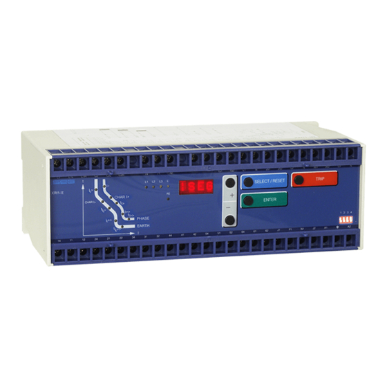
• Alphanumerical display (4 Digits) • Push buttons for setting and other operations • LEDs for measured value indication and setting Figure 3.4: Front plate XRI1-IE 3.2.2 LEDs The LEDs left from the display, L1, L2, L3, E are par- tially bi-colored, the green indicating measuring, and the red fault indication. -
Page 8: Display
Inquire password PSW? <TRIP><ENTER> Relay tripped TRIP <TRIP> or after fault tripping Secret password input XXXX <SELECT/RESET> <+><-><ENTER> System reset <SELECT/RESET> for about 3 s Table 3.1: Possible indication messages on the display, 1) only Modbus TB XRI1-IE 11.01 E... -
Page 9: Parameter Settings (See Chapter 6)
Baud rate der of the serial interface 1200; 2400; 4800; 9600 Parity bit of the serial interface Even; odd; no only Modbus protocol Table 3.2: Parameter values Additional parameters: Relay-type XRI1-IE Blocking mode Relay parameterizing Fault recorder Table 3.3 TB XRI1-IE 11.01 E... -
Page 10: Working Principle
1.25 ms (1.04 ms) for every measur- ing quantity. (16 scans per periode). Digital circuits The essential part of the XRI1-IE relay is a powerful microcontroller. All of the operations, from the analog digital conversion to the relay trip decision, are carried out by the microcontroller digitally. -
Page 11: Requirements On The Main Current Transformers
The low power consumption in the current circuit of XRI1-IE , namely <0.2 VA, has a positive effect on the selection of current transformers. It implies that, if an electromechanical relay is replaced by XRI1-IE , a high accuracy limit factor is automatically obtained by using the same current transformer. -
Page 12: General Operations And Settings
Figure 5.1: How to open the transparent cover The <TRIP>-push button is used to test the output relay circuits both for tripping and signalling. During normal operation it is also interlocked by means of the pass- word identification. TB XRI1-IE 11.01 E... -
Page 13: Indication Of Measuring Values And Fault
5.1.1 Indication of measuring values and fault data Indication in faultless condition In normal operation the display always shows |SEG. After pressing the push button <SELECT/RESET> the display switches cyclically to the next measuring value. After the measuring values had been indicated the set- ting parameters are displayed. -
Page 14: Dip Switches
Function Code Operation mode switches jumper position Password Normal position Password selection none Reset Output relays will be reset automatically Output relays will be reset manual/external/via software none Table 5.1: Summary of coding possibilities TB XRI1-IE 11.01 E... -
Page 15: Reset
Switch on dip switch 1. After power on and pressing <ENTER> then a password "-E+S" means pressing push buttons any push button, the relay XRI1-IE inquires for a new password. The text "PSW?" appears on the display. according to the follwing sequence: <->... -
Page 16: Relay Setting Principle
• High-range blockage input terminal C1/C1H • High-range reset input terminal C2/C2H 5.5.2 Blocking the protection function The blocking function of the XRI1-IE -relays can be set according to requirement. When pressing push buttons <ENTER> and <TRIP> at the same time the blocking mode is entered. -
Page 17: Operations And Settings
After pressing the <SELECT> push button, the present time delay setting value is shown on the display. The new setting value can then be changed by using <+> <-> push buttons. TB XRI1-IE 11.01 E... -
Page 18: Trip Delay For High Set Element
The CB failure protection function is deacti- vated again as soon as the phase currents have drop- ped to <1% x I within t 6.1.13 Trip delay for high set element CBFP of earth fault supervision (t IE>> (Similar to chapter 6.1.6) TB XRI1-IE 11.01 E... -
Page 19: Display Of The Activation Storage (Flsh/Nofl)
Assignment of the output relays: 6.1.19 Display of the activation storage Unit XRI1-IE has five output relays. The fifth output re- (FLSH/NOFL) lay is provided as permanent alarm relay for self su- If after an activation the existing current drops again pervision is normally on. - Page 20 1 _ _ _ IE> IE>> alarm _ _ _ 4 E>> E>> tripping 1 _ _ _ IE>> IE>> tripping _ _ _ _ CBFP Table 6.2: Example of assignment matrix of the output relay (default settings). TB XRI1-IE 11.01 E...
-
Page 21: Setting Value Calculation
L2, L3, E) and the four function LEDs (I>, I>>, IE> and The high set element is normally set to act for near-by IE>>) are equipped at XRI1-IE . If, for example an faults. A very good protective reach can be achieved... -
Page 22: Fault Recorder
• When fault recording is indicated (FLT1 etc), the Unit XRI1-IE has the following three possibilities to re- LEDs flash in compliance with the stored trip infor- set the display of the unit as well as the output relay at mation, i.e. -
Page 23: Relay Testing And Commissioning
3 seconds and all LEDs with a delay of 0.5 seconds, with the self-supervision relay dropping. Thereafter, re- set all output relays back to their normal positions by pressing the push button <SELECT/RESET> (about 3 s). TB XRI1-IE 11.01 E... -
Page 24: Test Circuit Of Xri1-Ie
Figure 7.1: Test circuit For testing relays one or three phase current test de- vices are required. Figure 7.1 shows an example of a single phase test circuit with adjustable current energiz- ing the XRI1-IE relay under test. TB XRI1-IE 11.01 E... -
Page 25: Checking The Input Circuits And Measured
In case of inverse time characteristics the injected cur- harmonics. Because the XRI1-IE relay measures only rent should be selected according to the characteristic the fundamental component of the input signals, the curve, e.g. -
Page 26: Checking The External Blocking And Reset Functions
In case of a XRI1-IE re- Remove the auxiliary supply voltage from the blocking lay with directional feature, the active and reactive input. -
Page 27: Technical Data
20% of the third harmonic; <0.08% per percent of the third harmonic up to 20% of the fifth harmonic; <0.07% per percent of the fifth harmonic Influences on delay times: no additional influences can be measured TB XRI1-IE 11.01 E... -
Page 28: Setting Ranges And Steps
CBFP 8.3.4 Interface parameter Function Parameter Modbus-Protocol RS485 Open Data Protocol Slave-Address 1 - 32 1 - 32 Baud-Rate* 1200, 2400, 4800, 9600 9600 (fixed) Parity* even, odd, no “even Parity” (fixed) * only Modbus Protocol TB XRI1-IE 11.01 E... -
Page 29: Inverse Time Overcurrent Protection Relay
Very Inverse (type B) − > Extremely Inverse (type C) − Where: = tripping time = time multiplier I> = fault current Is = Starting current TB XRI1-IE 11.01 E... -
Page 30: Inverse Time Characteristics
Very Inverse (type B) 1000 I> 0.02 t[s] t[s] I> > 10.0 0.03 I>> >> 0.03 0.05 0.01 0.01 5 6 7 8 9 10 Figure 8.4: Definite time overcurrent relay Figure 8.2: Extremely Inverse (type C) TB XRI1-IE 11.01 E... -
Page 31: Output Relays
For rated voltages 100 V, 110 V, 125 V, 220 V, 230 V Current consumption 1.5 mA DC at 360 V DC or 11.0 mA AC at 230 V DC Technical data subject to change without notice! TB XRI1-IE 11.01 E... -
Page 32: System Data And Test Specifications
10 V/m Surge immunity test as per EN 61000-4-5:EN 61000-4-5: 4 kV Radio interference suppression test as per EN 55011: limit value class B Radio interference radiation test as per EN 55011: limit value class B TB XRI1-IE 11.01 E... -
Page 33: Relay Case
Technical data subject to change without notice! Relay case Relay XRI1-IE is designed to be fastened onto a DIN-rail acc. to DIN EN 50022, the same as all units of the ROFESSIONAL The front plate of the relay is protected with a sealable transparent cover (IP40). -
Page 34: Order Form
Order form Time overcurrent relay XRI1- 3-phase measuring I>, I>> Rated current Earth current measuring Rated current RS485 Adjustable with Modbus protocol TB XRI1-IE 11.01 E... - Page 35 0.20 CBFP Nominal frequency LED Flash LED blinking after excitation FLSH Slave Address of serial interface Baud rate of the serial interface * 9600 Parity bit of the serial interface * even * only Modbus Protocol TB XRI1-IE 11.01 E...
- Page 36 I> tripping I>> alarm I>> tripping IE> alarm IE> tripping IE>> alarm IE>> tripping CBFP Assignment of the blocking functions Default settings Actual settings Function Blocked not blocked blocked not blocked I> I>> E> E>> CBFP TB XRI1-IE 11.01 E...
Need help?
Do you have a question about the XRI1-IE and is the answer not in the manual?
Questions and answers