Table of Contents
Advertisement
Quick Links
Advertisement
Table of Contents

Related Manuals for Seg MRN3


Summary of Contents for Seg MRN3
- Page 1 MRN3 Mains decoupling relay...
-
Page 2: Table Of Contents
Pre-trigger time (T 4.3.1 Selection of star or delta connection Adjustment of the clock Principle of frequency supervision Additional functions Measuring of frequency gradient (MRN3-2) 5.7.1 Setting procedure for blocking the Vector surge supervision (MRN3-1) protection functions 4.6.1 Measuring principle of vector surge... - Page 3 Checking the external blocking and reset functions Primary injection test Maintenance 7 Technical data Measuring input circuits Common data Setting ranges and steps 7.3.1 Interface parameter 7.3.2 Parameters for the fault recorder Output relays 8 Order form TB MRN3 12.00 E...
-
Page 4: Introduction And Application
• two parameter sets, • voltage supervision each with two step under-/ and Because of combination of three protectional functions in one device the MRN3 is a very compact mains de- overvoltage detection, • frequency supervision with three step under-/ or over- coupling device. -
Page 5: Design
3.1.4 Output relays The analog input voltages are galvanically decoupled The MRN3 is equipped with 5 output relays. Apart from by the input transformers of the device, then filtered and the relay for self-supervision, all protective functions can finally fed to the analog digital converter. The measur-... -
Page 6: Fault Recorder
3.1.5 Fault recorder The MRN3 has a fault value recorder which records the measured analog values as instantaneous values. The instantaneous values for star connection for delta connection are scanned at a raster of 1.25 ms (at 50 Hz) and 1.041 ms (at 60 Hz) and saved in a cyclic buffer. -
Page 7: Parameter Settings
= 07 minute m = 29 second s = 56 Table 3.6: Date and time The window for parameter setting is located behind the measured value display. The parameter window can be accessed via the <SELECT/RESET> key. TB MRN3 12.00 E... -
Page 8: Leds
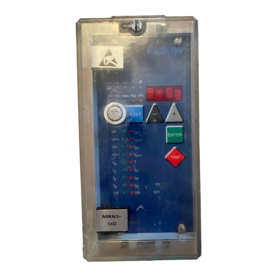
The LED marked with the letters FR is alight while the fault recorder is being adjusted. Figure 3.4: Front plate MRN3-1 Figure 3.5: Front plate MRN3-2 TB MRN3 12.00 E... -
Page 9: Working Principle
Digital circuits phases are decisive for energizing. The essential part of the MRN3 relay is a powerful mi- crocontroller. All of the operations, from the analog digi- tal conversion to the relay trip decision, are carried out by the microcontroller digitally. -
Page 10: Selection Of Star Or Delta Connection
Principle of frequency supervision connection All connections of the input voltage transformers are led The frequency element of MRN3 protects electrical to screw terminals. The nominal voltage of the device is generators, consumers or electrical operating equipment equal to the nominal voltage of the input transformers. -
Page 11: Vector Surge Supervision (Mrn3-1)
60 ms and 80 ms depending on the setting. Whereas the MRN3-1 detects mains failures within 60 ms without the restrictions described above because Vector surge supervision (MRN3-1) they are specially designed for applications where very The vector surge supervision protects synchronous gen- fast decoupling from the mains is required. -
Page 12: Measuring Principle Of Vector Surge Supervision
The mechanical shaft power is cause overfunctions, MRN3-1 should be connected balanced with the electrical feeded mains power, and separately to the busbar. - Page 13 This is named phase or vector The vector surge function of the MRN3-1 supervises vec- surge. tor surges in all three phases at the same time. Tripping of the relay can be adjusted for an one phase vector The MRN3-1 measures the cycle duration.
- Page 14 A further measure could be, that the load regulation at the utility connection point guarantees a minimum power flow of 15 - 20% of rated power. TB MRN3 12.00 E...
-
Page 15: Voltage Threshold Value For Frequency
Table 4.1: Dynamic behaviour of MRN3 functions Blocking function set in compliance with require- ments: The MRN3 has an external blocking input. By applying the auxiliary voltage to input D8/E8, the requested pro- tection functions of the relay are blocked (refer to 5.7.1). -
Page 16: Operation And Setting
Hz/s <SELECT/RESET><+><-> MRN3-2 ∆Θ + L1, L2 or L3 MRN3-1 vector surge tripping value in degree <SELECT/RESET><+><-> one time for each phase Delete failure memory wait <->... - Page 17 Inquire password PSW? <SELECT/RESET>/ <+>/<->/<ENTER> Relay tripped TRIP <TRIP> or fault tripping Secret password input XXXX <SELECT/RESET>/ <+>/<->/<ENTER> SEG System reset <SELECT/RESET> for about 3 s Table 5.1: Possible indication messages on the display TB MRN3 12.00 E...
-
Page 18: Setting Procedure
∆ ∆ ∆ ∆ /Y – Switch over 5.3.2 Depending on the mains voltage conditions, the input voltage transformers can be operated in delta or Y con- nection. Change-overs are effected via the <+> and the <-> keys and stored with <ENTER>. TB MRN3 12.00 E... -
Page 19: Setting Of Nominal Frequency
** Sample rate is variably adjusted to the momentarily measured frequency. 16 samples are always measured in one period. *** Sample rate setting is fixed to 50 Hz or 60 Hz. 16 samples per 20 ms or 16.67 ms are always measured. TB MRN3 12.00 E... -
Page 20: Display Of The Activation Storage (Flsh/Nofl)
S2_FR parameter set 2 can be activated via the blocking input and/or the fault recorder via the reset in- put. The relevant function is then activated by applying the auxiliary voltage to one of the external inputs. TB MRN3 12.00 E... -
Page 21: Protection Parameters
5.4.3 Threshold of frequency supervision 5.4.1 Parameter setting of over- and The frequency supervision of MRN3 has three frequency undervoltage supervision elements independent from each other. Acc. to setting The setting procedure is guided by two coloured LEDs. the pickup value above or below the nominal fre- During setting of the voltage thresholds the LEDs U<,... -
Page 22: Parameter Setting Of Vector Surge Supervision (Mrn3-1)
False tripping of the MRN3 in such cases is prevented If possible the test described under a) and b) should be by an adjustable voltage threshold U . - Page 23 If the fault recorder is used, the frequency should be set measured value display. The parameter window can be to f = 50 Hz or f = 60 Hz (see chapter 5.3.3). accessed via the <SELECT/RESET> key. TB MRN3 12.00 E...
- Page 24 The relays are assigned as follows: LEDs U<, U<<, U> The blocking function of the MRN3 can be set accord- ing to requirement. By applying the aux. voltage to and U>>, f1, f2, f3 are two-coloured and light up D8/E8, the functions chosen by the user are blocked.
- Page 25 1 _ _ _ tf3 red ∆Θ ∆Θ red tripping _ _ _ 4 df/dt tripping _ _ _ 4 df/dt red Tabelle 5.4: Example of assignment matrix of the output relay (default settings). TB MRN3 12.00 E...
- Page 26 L3, f) and the four function LEDs (U<, U<<, U>, U>>, dures where high positive and negative df/dt values f1, f2, f3, ∆Θ und df/dt) are equipped at MRN3. Not occur, but they do not cause any tripping due to the only fault messages are transmitted, the display also in- special measuring method.
- Page 27 Fault memory When the relay is energized or is energized or trips, all Recorded fault data: fault data and times are stored in a non-volatile memory manner. The MRN3 is provided with a fault value re- Measuring Displayed value Correspond- corder for max.
-
Page 28: Relay Testing And Commissioning
As relay input energizing quantities, three phase volt- red). An undervoltage condition has been detected after ages should be applied to MRN3 relay input circuits. power-on, because no input voltages are applied to the Depending on the system conditions and the voltage relay. -
Page 29: Secondary Injection Test
• switching device and • Test leads and tools Example of test circuit For testing of the MRN3 relay, a three phase voltage source with adjustable voltage and frequency is re- quired. Figure 6.1 shows an example of a three-phase test circuit energizing the MRN3 relay during test. -
Page 30: Checking The Input Circuits And Measuring Functions
The vector surge is indicated on the display in degrees of the over/undervoltage functions (for MRN3-1): LED ∆Θ (Indication ∆Θ in °) To check the relay's operating time, a timer must be The rate of change of frequency (LED df) is indicated on... -
Page 31: Checking The Relay Operating Time Of The Over/Underfrequency Functions
R may be assumed zero. Thus, the value of R obtained to test the vector surge function of MRN3 re- may be calculated using the following simplified for- lay. If there is no such testing facility available, a very... -
Page 32: Checking The External Blocking And Reset Functions
• The combined measuring functions of MRN3 relays enable supervision the relay functions during service. Primary injection test • The combined TRIP test function of the MRN3 relay al- lows to test the relay output circuits. Generally, a primary injection test could be carried out... -
Page 33: Technical Data
Aux. voltage: in the range <0.8 U <1.2 no additional influences to be measured Frequency: no influences Influences on delay time: no additional influences to be measured GL-Approbation: 98776-96HH Bureau Veritas Approbation: 2650 6807 A00 H TB MRN3 12.00 E... -
Page 34: Setting Ranges And Steps
12...230 V = 400 V: 20...400 V Table 7.1: Setting ranges and steps At 50 Hz rated frequency At 60 Hz rated frequency min. time delay; t = (T+1) x 20 ms only Modbus f,min f,min TB MRN3 12.00 E... -
Page 35: Interface Parameter
Table 7.2: Parameters for the fault recorder * is written over when a new trigger signal arrives Output relays Relay type Trip relays / change-over contacts Alarm relays / change-over contacts MRN3 Table 7.3: Output relays TB MRN3 12.00 E... -
Page 36: Order Form
Voltage, frequency and df/dt-supervision Rated voltage 100 V 230 V 400 V Housing (12TE) 19“-rack Flush mounting RS485 Alternatively with Modbus Protocol Technical data subject to change without notice! TB MRN3 12.00 E... - Page 37 10/23/40* measuring (or df/dt) Slave address of the serial interface RS** Baud-Rate 9600 RS** Parity-Check even * thresholds dependent on rated voltage 100 V / 230 V / 400 V ** only Modbus TB MRN3 12.00 E...
- Page 38 U< alarm tripping U< U<< alarm tripping U<< U> alarm tripping U> U>> alarm tripping U>> f1 alarm tf1 tripping f2 alarm tf2 tripping f3 alarm tf3 tripping ∆Θ tripping df/dt tripping TB MRN3 12.00 E...
- Page 39 All settings must be checked at site and should the occasion arise, adjusted to the object/item to be protected. This technical manual is valid for software version number: D01-8.08 (MRN3-1) D04-8.08 (MRN3-2) Modbus version number: D51-1.13 (MRN3-1) D54-1.13 (MRN3-2) TB MRN3 12.00 E...
- Page 40 TB MRN3 12.00 E...
Need help?
Do you have a question about the MRN3 and is the answer not in the manual?
Questions and answers