Table of Contents
Advertisement
Quick Links
Advertisement
Table of Contents

Related Manuals for Seg MRU3-1


Summary of Contents for Seg MRU3-1
- Page 1 MRU3-1 AC voltage relay –...
-
Page 2: Table Of Contents
8 Order form Parameter for the fault recorder 5.5.1 Adjustment of the fault recorder 5.5.2 Number of the fault recordings 5.5.3 Adjustment of trigger occurences 5.5.4 Pre-trigger time (T Date and time 5.6.1 Adjustment of the clock TB MRU3-1 12.00 E... -
Page 3: Introduction And Application
Introduction and application Features and characteristics • Microprocessor technology with watchdog, The voltage supervision relay MRU3-1 protects electri- • digital filtering of the measured values by using dis- cal power generators, consumers or operating com- ponents generally against over- or undervoltages. -
Page 4: Design
Design Connections Figure 3.1: Connection of the MRU3-1 to phase-to-phase voltage Note: Connection of phase-to-neutral voltage is possible too. 3.1.1 Analog input circuits The external wiring of the measuring circuits are shown in the connection diagram. The analog input voltages... -
Page 5: Output Relays
3.1.5 Fault recorder The MRU3-1 has a fault value recorder which records the measured analog values as instantaneous values. The instantaneous values Figure 3.3: Division of the memory into 8 segments, for example... -
Page 6: Parameter Settings
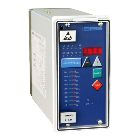
Year Y = 00 Month M = 04 D = 18 Hour h = 07 Minute m = 59 Second s = 23 Additional functions Blocking function Relay configuration Figure 3.5: Front plate MRU3-1 Fault memory TB MRU3-1 12.00 E... -
Page 7: Working Principle
Digital circuits ated for overvoltage supervision and the lowest volt- age for undervoltage supervision. The essential part of the MRU3-1 relay is a powerful microcontroller. All of the operations, from the analog A distinction is made between 1-phase and 3-phase digital conversion to the relay trip decision, are carried tripping. -
Page 8: Selection Of Star Or Delta Connection
Table 4.1: Dynamic behaviour of MRU3-1 functions > Blocking function set in compliance with require- ments: The MRU3-1 has an external blocking input. By apply- ing the auxiliary voltage to input D8/E8, the re- )& quested protection functions of the relay are blocked (refer to chapter 5.9.1) -
Page 9: Operations And Settings
Inquire password PSW? <SELECT/RESET>/ <+>/<->/<ENTER> Relay tripped TRIP <TRIP> or fault tripping Secret password input XXXX <SELECT/RESET>/ <+>/<->/<ENTER> SEG System reset <SELECT/RESET> for about 3 s only Modbus Table 5.1: Possible indication messages on the display TB MRU3-1 12.00 E... -
Page 10: Setting Procedure
** Sample rate is variably adjusted to the momentarily measured frequency. 16 samples are always measured in one period. *** Sample rate setting is fixed to 50 Hz or 60 Hz. 16 samples per 20 ms or 16.67 ms are always measured. TB MRU3-1 12.00 E... -
Page 11: Display Of The Activation Storage
Parameter switch B_FR External trigger- Reset input Note ing of the fault When the MRU3-1 is to be used for measuring the re- recorder sidual voltage in systems with isolated or compensated R_FR Blocking input External trigger- neutral or as generator earth fault protection, the... -
Page 12: Parameter Setting Of Over- And Under
The undervoltage supervision (U< and U<<) as well as the overvoltage supervision (U> and U>>) can be de- The MRU3-1 is equipped with a fault recorder (see activated by setting the threshold to "EXIT". chapter 3.1.5). Three parameters can be determined. -
Page 13: Adjustment Of Trigger Occurences
M=01 front plate optically. For this purpose, the three LEDs D=01 (L1, L2, L3) and the four function LEDs (U<, U<<, U>, U>>) are equipped at MRU3-1. Not only fault mes- Time : Hour h=00 sages are transmitted, the display also indicates the... -
Page 14: Fault Memory
Fault memory When the relay is energized or is energized or trips, Recorded fault data: all fault data and times are stored in a non-volatile memory manner. The MRU3-1 is provided with a fault Measuring Displayed value Correspond- value recorder for max. five fault occurrences. In the... -
Page 15: Additional Functions
5.9.1 Setting procedure for blocking the protection functions The blocking function of the MRU3-1 can be set ac- The relays are assigned as follows: LEDs U<, U<<, U> cording to requirement. By applying the aux. voltage and U>> are two-coloured and light up green when... -
Page 16: Reset
Tripping 1 _ _ _ tU> red U>> Alarm _ _ _ _ U>> green tU>> Tripping _ 2 _ _ tU>> red Table 5.5: Example of assignment matrix of the output relay (defaults settings) TB MRU3-1 12.00 E... -
Page 17: Relay Testing And Commissioning
3 s to reset the LEDs and "TRIP" message. measured and evaluated. (see chapter 5.9.1) NOTE! For MRU3-1 relay used for earth fault protection be sure that the frequency set value (f=50/60) has been selected correctly according to your system frequency (50 or 60 Hz). -
Page 18: Secondary Injection Test
• Test leads and tools 6.4.2 Example of the test circuit For testing of the MRU3-1 relay, a three phase voltage source is required. Figure 6.1 shows an example of a three-phase test circuit energizing the MRU3-1 relay during test. The three phase voltages are applied to the relay in Y-connection. -
Page 19: Checking The Input Circuits And Measuring Functions
Furthermore, gradually decrease (increase) the volt- ages until the relay resets, i.e. the voltage alarm output relay is disengaged. Check that the dropout to pickup ratio is greater than 0.97 (for overvoltage function) or smaller than 1.03 (for undervoltage). TB MRU3-1 12.00 E... -
Page 20: Primary Test
In actual service, for example, the measured voltage values on the MRU3-1 relay display may be com- pared phase by phase with the concerned indications of the instruments of the switchboard to verify that the relay works and measures correctly. -
Page 21: Technical Data
20 % of the 3rd harmonic <0.1 % per percent of the 3rd harmonic up to 20 % of the 5th harmonic <0.05 % per percent of the 5th harmonic GL-Approbation: 98776-96HH Bureau Veritas Approbation: 2650 6807 A00 H TB MRU3-1 12.00 E... -
Page 22: Setting Ranges And Steps
(60 Hz) Savings of the recording at the occurence P_UP; TRIP; A_PI; TEST Pre-trigger-time 0.05 s – 8.00 s *is written over when a new trigger signal arrives Output relays Trip relays/change-over contacts Alarm relaya/change-over contacts MRU3 TB MRU3-1 12.00 E... -
Page 23: Order Form
Rated voltage 100 V 230 V 400 V Housing (12TE) 19“-rack Flash mounting RS 485 Alternatively with Modbus protocol Technical data subject to change without notice! TB MRU3-1 12.00 E... - Page 24 120/270/480* Tripping delay for overvoltage element 0.04 U>> Slave address of the serial interface RS** Baud-Rate 9600 RS** Parity-Check even * thresholds dependent on rated voltage 100 V / 230 V / 400 V **only Modbus TB MRU3-1 12.00 E...
- Page 25 Relay 3 Relay 4 Default Actual Default Actual Default Actual Default Actual settings settings settings settings settings settings settings settings U< alarm tripping U< U<< alarm tripping U<< U> alarm tripping U> U>> alarm tripping U>> TB MRU3-1 12.00 E...
- Page 26 Low/High-range for reset input Low/High-range for blockage input Default settings Actual settings Default settings Actual settings Low=plugged High=not plugged This technical manual is valid for For software-Version number: D06-7.01 (MRU3-1) D07-8.01 (MRU3-2) Modbus-version number: D56-1.01 (MRU3-1-M) D57-1.01 (MRU3-2-M) TB MRU3-1 12.00 E...
Need help?
Do you have a question about the MRU3-1 and is the answer not in the manual?
Questions and answers