Table of Contents
Advertisement
Quick Links
Advertisement
Table of Contents

Related Manuals for Seg XRN2


Summary of Contents for Seg XRN2
- Page 1 XRN2 Mains decoupling relay...
-
Page 2: Table Of Contents
7.4.2 Example of test circuit Measuring of frequency gradient 7.4.3 Checking the input circuits and (XRN2-2) measuring functions Vector surge supervision (XRN2-1) 7.4.4 Checking the operating and resetting 4.6.1 Measuring principle of vector surge values of the over/undervoltage supervision functions Voltage threshold value for frequency 7.4.5... -
Page 3: Introduction And Application
• Voltage supervision each with two step under-/ and Because of combination of three protectional functions overvoltage detection in one device the XRN2 is a very compact mains de- • Frequency supervision with three step under-/ or coupling device. Compared to the standardly used... -
Page 4: Design
3.1.1 Analog input circuits 3.1.4 Output relays The analog input voltages are galvanically decoupled The XRN2 has 5 output relays. One trip relay with two by the input transformers of the device, then filtered and changeover contacts. One alarm relay with two finally fed to the analog digital converter. -
Page 5: Data Communication
HTL/PL-Soft3, which will be provided on request to- gether with the relay. The XRN2 can be connected to other units of the via interface. If there are more than ROFESSIONAL one relay in the system, the last relay of the chain has to be provided with a line termination resistor. -
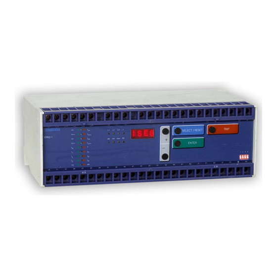
Page 6: Front Plate
Front plate 3.2.1 Indication- and operation elements The front plate of the XRN2-protection relay comprises the following operation and indication elements: • Alphanumerical display (4 Digits) • Push buttons for setting and other operations • LEDs for measured value indication and setting Fig. -
Page 7: Display
LED of blocked parameter f, ∆Θ, df Undervoltage blocking of setting value in Volt <SELECT/RESET><+><-> frequency and vector surge meas- uring (df/dt for XRN2-2) Slave address of serial interface 1 - 32 <SELECT/RESET><+><-> Recorded fault data: tripping values in Volt <SELECT/RESET><+><->... -
Page 8: Leds
The LED marked with letters RS lights up during setting of the slave address of the device for serial data com- munication. 3.2.4 Front plate XRN2-1 3.2.5 Front plate XRN2-2 TB XRN2 02.00 E... -
Page 9: Parameter Settings
3.2.6 Parameter settings Setting XRN2-1 XRN2-2 parameter ∆/Y U< U< U<< U<< U> U> U>> U>> ∆Θ < RS485/ Slave Table 3.2: Sequence of parameter setting of the two relay types TB XRN2 02.00 E... -
Page 10: Working Principle
Digital circuits phases are decisive for energizing. The essential part of the XRN2 relay is a powerful mi- crocontroller. All of the operations, from the analog digital conversion to the relay trip decision, are carried out by the microcontroller digitally. -
Page 11: Selection Of Star Or Delta Connection
4.3.1 Selection of star or delta connection Principle of frequency supervision All connections of the input voltage transformers are led The frequency element of XRN2 protects electrical to screw terminals. The nominal voltage of the device is generators, consumers or electrical operating equip- equal to the nominal voltage of the input transformers. -
Page 12: Vector Surge Supervision (Xrn2-1)
0.5 Hz/s up to over reclosings is not possible with this kind of relay. 2 Hz/s. The XRN2 detects the instantaneous frequency gradient df/dt of each mains voltage period in an in- Frequency relays are partial unsuitable because only a highly loaded generator decreases its speed within terval of one half period each. -
Page 13: Measuring Principle Of Vector Surge
The mechanical shaft power is cause overfunctions, XRN2-1 should be connected balanced with the electrical feeded mains power, and separately to the busbar. - Page 14 This is named phase or vector The vector surge function of the XRN2-1 supervises vec- surge. tor surges in all three phases at the same time. Tripping of the relay can be adjusted for an one phase vector The XRN2-1 measures the cycle duration.
- Page 15 A further measure could be, that the load regulation at the utility connection point guarantees a minimum power flow of 15 - 20% of rated power. TB XRN2 02.00 E...
-
Page 16: Voltage Threshold Value For Frequency Measuring
Table 4.1: Dynamic behaviour of XRN2 functions Blocking function set in compliance with require- ments : The XRN2 has an external blocking input. By applying the auxiliary voltage to input C1/C1L or C1/C1H, the requested protection functions of the relay are blocked (refer to 6.2.10). -
Page 17: Operation And Setting
(see 5.4.2). The <TRIP>-push button is used to test the output relay circuits both for tripping and signalling. During normal operation it is also interlocked by means of the pass- word identification. TB XRN2 02.00 E... -
Page 18: Indication Of Measuring Values And
5.1.1 Indication of measuring values and fault data Indication in faultless condition In normal operation the display always shows |SEG. After pressing the push button <SELECT/RESET> the display switches cyclically to the next measuring value. After the measuring values had been indicated the set- ting parameters are displayed. -
Page 19: Dip Switches
DIP switches Dip switch 3 OFF: On the front plate of the XRN2-relay there is one DIP switch to preset the following functions: All output relays will be reset automatically after the • Password programming fault has been rectified, (e.g. when the fault current is •... -
Page 20: Reset
Apply dip switch 1. After power on and pressing any <+> <ENTER> push button, the relay XRN2 inquires for a new pass- then a password "-E+S" means pressing push buttons word. The text "PSW?" appears on the display. The new password is entered by any combination of the according to the follwing sequence: <->... -
Page 21: Relay Setting Principle
5.5.1 Setting of default parameters voltage. The operating threshold of the blocking and reset inputs, however, has to be defined by taking the Setting of the XRN2 default parameters can be done supply voltage into account. The following two different as follows: operating thresholds can be adjusted: •... -
Page 22: Special Settings
When setting the tripping delay to "EXIT" the value is in- finit meaning only warning, no tripping. XRN2-1 only: Vector surge tripping 1-of-3/3-of-3 ∆Θ Pickup value for vector surge in degree TB XRN2 02.00 E... -
Page 23: Setting Of Nominal Frequency
First the nominal frequency (50 or 60 Hz) has to be The frequency supervision of XRN2 has three frequency correctly set before unit XRN2 is put into operation. elements independent from each other. Acc. to setting All frequency functions are determined by setting the the pickup value above or below the nominal fre- nominal frequency, i.e. -
Page 24: Parameter Setting Of Vector Surge
If possible the test described under a) and b) should be False tripping of the XRN2 in such cases is prevented double checked by a real auto reclosing. by an adjustable voltage threshold U . -
Page 25: Setting Procedure For Blocking The Protection Functions
6.2.10 Setting procedure for blocking the protection functions Min./max. frequency measuring : The blocking function of the XRN2 can be set accord- The XRN2 ascertains the actual frequency from each ing to requirement. By applying the aux. voltage to C1/C1L or C1/C1H, the functions chosen by the user cycle of the system voltage. -
Page 26: Reset
<SELECT/RESET> push button (see also communica- tion protocol of RS485 interface) The display can only be reset when the pickup is not present anymore (otherwise "TRIP" remains in display). During resetting of the display the parameters are not affected. TB XRN2 02.00 E... -
Page 27: Relay Testing And Commissioning
As relay input energizing quantities, three phase volt- "TRIP" on the display and LED L1, L2, L3 and U< light ages should be applied to XRN2 relay input circuits. up red). An undervoltage condition has been detected Depending on the system conditions and the voltage... -
Page 28: Secondary Injection Test
• Switching device • Test leads and tools 7.4.2 Example of test circuit For testing of the XRN2 relay, a three phase voltage source with adjustable voltage and frequency is re- quired. Figure 7.1 shows an example of a three-phase test circuit energizing the XRN2 relay during test. -
Page 29: Checking The Input Circuits And
(system frequency = 50.01Hz, Indication = 5001) The vector surge is indicated on the display in degrees (for XRN2-1): LED ∆Θ (Indication ∆Θ in °) 7.4.5 Checking the relay operating time of The rate of change of frequency (LED df) is indicated... -
Page 30: Checking The Relay Operating Time Of
(vector surge) on the voltage signal can be C, says 3 µF (400 VAC), the value of R may be calcu- obtained to test the vector surge function of XRN2 re- lated using the following simplified formula: lay. If there is no such testing facility available, a very simple simulation circuit may be used to test the vector ∆Θ... -
Page 31: Checking The External Blocking And Reset Functions
• the combined measuring functions of the XRN2 relay Primary injection test enable supervision the relay functions during service. • the combined TRIP test function of the XRN2 relay al- Generally, a primary injection test could be carried out lows to test the relay output circuits. -
Page 32: Technical Data
Aux. voltage: in the range <0.8 U <1.2 no additional influences to be measured Frequency: no influences Influences on delay time: no additional influences to be measured GL-Approbation: 98776-96HH Bureau Veritas Approbation: 2650 6807 A00 H TB XRN2 02.00 E... -
Page 33: Setting Ranges And Steps
= 400 V: 20...400 V Serial Interface 1 - 32 Table 7.1: Setting ranges and steps At 50 Hz rated frequency At 60 Hz rated frequency = (T+1) ⋅ 20 ms min. time delay; t f,min f,min TB XRN2 02.00 E... -
Page 34: Output Relays
Current consumption 1 mA DC bei 24 V High-range: ≥70 V ≤60 V For rated voltages 100 V, 110 V, 125 V, 220 V, 230 V Current consumption 1.5 mA DC 270 V or 11.0 mA AC TB XRN2 02.00 E... -
Page 35: System Data And Test Specifications
10 V/m Surge immunity test as per EN 61000-4-5: EN 61000-4-5: 4 kV Radio interference suppression test as per EN 55011: limit value class B Radio interference radiation test as per EN 55011: limit value class B TB XRN2 02.00 E... -
Page 36: Relay Case
Technical data subject to change without notice! Relay case Relay XRN2 is designed to be fastened onto a DIN-rail acc. to DIN EN 50022, the same as all units of the ROFESSIONAL The front plate of the relay is protected with a sealable transparent cover (IP40). -
Page 37: Order Form
Order form Mains decoupling relay XRN2- with voltage-, frequency and vector surge supervision Voltage, frequency and df/dt-supervision Rated voltage: 100 V 230 V 400 V TB XRN2 02.00 E... - Page 38 ° < voltage threshold value for frequency and vector 10/23/40* surge measuring (or df/dt) Slave address of the serial interface * thresholds dependent on rated voltage 100 V / 230 V / 400 V TB XRN2 02.00 E...
- Page 39 Default setting BLOC BLOC NO_B NO_B BLOC BLOC NO_B BLOC BLOC Actual setting Setting of dip switches Dip switch Default Actual Default Actual Default Actual Default Actual setting setting setting setting setting setting setting setting TB XRN2 02.00 E...
- Page 40 TB XRN2 02.00 E...
Need help?
Do you have a question about the XRN2 and is the answer not in the manual?
Questions and answers