
Related Manuals for Seg HighTECH Line MRM3


Summary of Contents for Seg HighTECH Line MRM3
- Page 1 MANUAL HighTECH Line PROTECTION TECHNOLOGY MADE SIMPLE MRM3 MOTOR PROTECTION RELAY MOTOR PROTECTION RELAY Original document English Revision: B...
- Page 2 SEG Electronics GmbH Manual MRM3-2 SEG Electronics reserves the right to update any portion of this publication at any time. Information provided by SEG Electronics is believed to be correct and reliable. However, no responsibility is assumed by SEG Electronics unless otherwise expressly undertaken.
-
Page 3: Table Of Contents
Manual MRM3-2 SEG Electronics GmbH Contents Introduction and Application ..............6 Characteristics and Features ..............7 Design ......................8 Connections ........................8 3.1.1 Analog Inputs ........................9 3.1.2 Output Relays ........................9 3.1.3 Digital Inputs ........................10 3.1.4 Low/High Range of the Digital Inputs ................10 Front plate ......................... - Page 4 SEG Electronics GmbH Manual MRM3-2 5.5.7 Start-up recognition time or Motor Running time ............28 5.5.8 Stopping time ........................ 28 Interface Parameters ......................28 5.6.1 Adjustment of the Slave-Address (RS) ................. 28 5.6.2 Adjustment of the Baud-Rate (only for Modbus Protocol) ..........28 5.6.3...
- Page 5 Manual MRM3-2 SEG Electronics GmbH 7.4.3 Initial load factor ......................54 7.4.4 Tripping of t2x and t6x - times ..................55 7.4.5 Inverse time over current protection................56 7.4.6 Trip characteristics ......................57 7.4.7 Inverse Time Characteristic for Load Unbalance ............61 Output relays ........................
-
Page 6: Introduction And Application
SEG Electronics GmbH Manual MRM3-2 1. Introduction and Application The motor protection relay MRM3-2 offers reliable protection for LV and MV motors which are ei- ther operated via power contactors or power circuit breakers. The following functions are integrated into this relay: ... -
Page 7: Characteristics And Features
Manual MRM3-2 SEG Electronics GmbH 2. Characteristics and Features Microprocessor technology with self-supervision, Measuring of phase currents as RMS value, Digital filtering of the earth current with discrete Fourier analysis, by which the influence of interference signals, such as harmonics and transient DC components during an earth- fault are suppressed. -
Page 8: Design
SEG Electronics GmbH Manual MRM3-2 3. Design Connections Figure 3.1: Connection Diagram MRM3-2 Figure 3.2: Measuring of phase currents and earth current detection in Holmgreen connection (IE) This kind of connection can be used where three phase CTs are available and a combination of phase and earth current measuring is required. -
Page 9: Analog Inputs
Manual MRM3-2 SEG Electronics GmbH Figure 3.3: Measuring of earth current with core-type CT (IE) With the combination of phase and earth current measuring, CTs to be connected according to Figure 3.2. and Figure 3.3. 3.1.1 Analog Inputs The analog input signals of the phase currents I... -
Page 10: Digital Inputs
SEG Electronics GmbH Manual MRM3-2 3.1.3 Digital Inputs The MRM3-2 has 7 digital inputs with fixed functions. All inputs have a common reference point : Terminal D8. (See Chapter 3.1) Terminal Function Coding Plug External reset External blocking Parameter set change-over switch External trigger for the fault recorder Identification „Motor Running“... -
Page 11: Front Plate
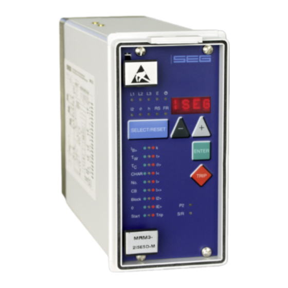
Manual MRM3-2 SEG Electronics GmbH Front plate Figure 3.5: Front plate MRM3-2-IE Figure 3.6: Front plate MRM3-2-I DOK-TD-MRM3-2, Rev. B... -
Page 12: Indicating Leds
SEG Electronics GmbH Manual MRM3-2 The LEDs , h, RS and FR on the MRM3-2 emit a yellow light, all other LEDs are bi-colored. The LEDs at the left next to the alphanumerical display give a green light during measuring and a red one when a fault signal occurs. -
Page 13: Digital Part
Manual MRM3-2 SEG Electronics GmbH Digital part The protection relay is equipped with a powerful micro-controller, being the core element of the pro- tection unit. With this micro-controller all tasks are completely digitally processed, from discretisa- tion of the measuring quantities to protective tripping. -
Page 14: Working Principle
SEG Electronics GmbH Manual MRM3-2 4. Working Principle Start Recognition The MRM3-2 monitors the flow of the current from which the following operational conditions of the motor are gathered. STOP START RUNNING Figure 4.1: Different Start-Up Behavior of Motors STOP - Condition: If no current can be measured (I <... - Page 15 Manual MRM3-2 SEG Electronics GmbH Overload Threshold: This corresponds to the permissible thermal continuous current k x IB and is adjusted by the parameter of the thermal image. Starter Recognition Time: This adjustable time has only to be extended for special start procedures in order to prevent that the RUNNING conditions are indicated too early in advance.
-
Page 16: Criteria For Blocking The Start
SEG Electronics GmbH Manual MRM3-2 4.1.1 Criteria for Blocking the Start Number of monitored starts : The MRM3-2 is equipped with a flexible supervision element which can limit the sequence of pos- sible starts. A start should be prevented if it is obvious that it is likely to be interrupted due to overload so that in total the down-time can be curtailed. - Page 17 Manual MRM3-2 SEG Electronics GmbH Figure 4.4: Relation Start Period/Start Blocking Time with firm Start Blocking Time Thermal Image A start is always possible as long as there is enough thermal reserve for a start. This start limitation is a dynamic one and is orientated on the data the thermal image is parameterized with. For this the MRM3-2 detects the average thermal load of the latest starts.
-
Page 18: Starting Time
SEG Electronics GmbH Manual MRM3-2 Starting time With certain applications it is possible that the starting phase of the engines is extended. One rea- son for this insufficient terminal voltage which may be caused by the high starting current or by a high grid load in general. -
Page 19: Requirement On The Main Current Transformers
Manual MRM3-2 SEG Electronics GmbH Requirement on the Main Current Transformers The CTs chosen have a considerable influence on the accuracy of the protective system. In order to select the right type of transformer, the requirements and conditions on site have to be consid- ered carefully. -
Page 20: Operation And Adjustments
SEG Electronics GmbH Manual MRM3-2 5. Operation and Adjustments Displayed text for parameter settings Function Displayed Text Related LED References Normal operation Exceeding the measuring range max. Sec. transf. currents indication L1, L2, L3,E Chap. 5.3.1 Rated frequency f = 50 / f = 60 Chap. -
Page 21: Setting Procedure
Manual MRM3-2 SEG Electronics GmbH Setting Procedure <SELECT/RESET> short advancing the indication long reset <ENTER> Saving of an entry Before parameters can be set a password is inquired (see chapter 4.4 of description ”MR – Digital Multifunction Relay”). System parameters 5.3.1 Presentation of Measuring Values as Primary Quantities on the Dis-... -
Page 22: Parameter Set Changeover Switch (P2)
SEG Electronics GmbH Manual MRM3-2 5.3.6 Parameter Set Changeover Switch (P2) By means of this switch two different parameter sets can be activated. The changeover procedure can be realized either by the software or via the digital input (A2). If the parameter set changeover switch is adjusted to ”SET2“, the active parameter set can be changed to ”SET1“... -
Page 23: T2X And T6X Minimal Trip Time During The Starting Process
Manual MRM3-2 SEG Electronics GmbH 5.4.5 t2x and t6x Minimal Trip Time During the Starting Process. With this parameter the fastest trip time during the start-up phase is limited for the thermal image. If the selected pick-up value k x I is exceeded by two times or six times, the characteristic breaks to definite time. -
Page 24: Tripping Time Or Time Factor For The Phase Over Current Element (I>+T>)
SEG Electronics GmbH Manual MRM3-2 5.4.9 Tripping Time or Time Factor for the Phase Over current Element (I>+t>) Normally, after change of the trip characteristics, the tripping time or the time factor also has to be changed accordingly. In order to avoid an unsuitable combination between trip characteristics and tripping time or time factor, the following measures are initiated by the MRM3-2: The LED for adjustment of the tripping time or time factor (I>... -
Page 25: Negative Phase Sequence
Manual MRM3-2 SEG Electronics GmbH 5.4.12 Negative Phase Sequence Load unbalance can, for example, be caused by a phase failure or fault in a one motor winding. Load unbalances give rise to negative phase sequence currents in the stator, causing odd harmon- ics in the stator winding and even harmonics in the rotor winding. -
Page 26: Tripping Time Or Time Factor For The Earth Fault Element (Ie>+T>)
SEG Electronics GmbH Manual MRM3-2 5.4.16 Tripping Time or Time Factor for the Earth Fault Element (IE>+t>) The setting procedure outlined in chapter 5.4.9 applies here as well. 5.4.17 Reset Time for the Earth Fault Element (IE>+CHAR+t>) The setting procedure outlined in chapter 5.4.10 applies here as well. -
Page 27: Start Supervision
Manual MRM3-2 SEG Electronics GmbH Start Supervision The MRM3-2 can offer two start supervision methods: Automatically by means of the thermal load By a limited number of starts per time interval 5.5.1 Duration of a Start Cycle (No.+Start) -
Page 28: Maximal Start Time (Start+T>)
SEG Electronics GmbH Manual MRM3-2 5.5.6 Maximal Start Time (Start+t>) Exceedingly long acceleration can only be recognized if the threshold k*I is once overshot after the STOP threshold was exceeded. With the setting "DEFT" The time meter for the max. start time is activated upon exceeding of the threshold k*I >. -
Page 29: Recorder (Fr)
Manual MRM3-2 SEG Electronics GmbH Recorder (FR) 5.7.1 Fault Recorder or Disturbance Recorder The existing store can be utilized in two ways: Not to be overwritten Previous recordings will not be overwritten. When there is no memory space left, further recordings are not possible. -
Page 30: Number Of Fault Recordings
SEG Electronics GmbH Manual MRM3-2 Each of the storage segments have a fixed storage time where the time before the trigger event can be defined. Via the RS485 interface the data can be read out by means of a PC provided with HTL/PL-Soft4. -
Page 31: Pre-Trigger Time
Manual MRM3-2 SEG Electronics GmbH Setting of the Clock When date and time are set, the LED „ “ is on. The following method is used: Date: year Y=00 month M=00 D=00 time: hour h=00 minute m=00 second s=00 Immediately when the supply voltage is applied the clock starts with the respective date and time. -
Page 32: Additional Functions
SEG Electronics GmbH Manual MRM3-2 Additional Functions 5.9.1 Blocking of the Protective Functions Blocking of the protective functions After voltage has been applied to blocking input D8/E8, the intended reaction for each of the protective functions can be defined individually. (Observe voltage adjustment !) See chapter 3.1.4... -
Page 33: Allocation Of The Reset Functions
Manual MRM3-2 SEG Electronics GmbH 5.9.2 Allocation of the Reset Functions When setting of the parameters for the blocking function is completed you are in the allocation mode for the reset functions. Whether the assigned relay should be reset manually or automatically after activation or trip can be allocated to each of the activation or trip elements. -
Page 34: Allocation Of The Output Relays
SEG Electronics GmbH Manual MRM3-2 5.9.3 Allocation of the Output Relays The MRM3-2 has five output relays. The fifth output relay is an alarm relay for the self-supervision and its al-location is fixed; it is operated acc. to the closed circuit principle. - Page 35 Manual MRM3-2 SEG Electronics GmbH Relay functions Output relays Displayed Corresponding LED figures Symbol Function > > red Alarm _ 2 _ _ > x k Alarm _ 2 _ _ > green > x k Tripping 1 _ _ _ >...
-
Page 36: Measuring Value And Fault Indications
SEG Electronics GmbH Manual MRM3-2 5.10 Measuring Value and Fault Indications 5.10.1 Measuring Value Indications The following measuring values can be displayed during normal operation: Current in phase 1 (LED L1 green), Current in phase 2 (LED L2 green), ... -
Page 37: Fault Memory
Manual MRM3-2 SEG Electronics GmbH 5.10.4 Fault Memory In case of actuation or tripping of the relay, the fault values and times are stored in a voltage fail- safe way. The MRM3-2 has a fault value memory covering up to 25 fault events. If this number is exceeded, the eldest data set is then overwritten. -
Page 38: Reset
SEG Electronics GmbH Manual MRM3-2 3. Values recorded after a tripping action Tripping current in Phase 1, Tripping current in Phase 2, Tripping current in Phase 3, Tripping value for earth current E, Tripping value for load-unbalance current I2, ... -
Page 39: Digital Inputs
Manual MRM3-2 SEG Electronics GmbH 5.12 Digital Inputs 5.12.1 Parameter Set Changeover Switch When voltage is applied to this input it is changed over to the other parameter set. 5.12.2 External Trigger of the Fault Recorder Via this input fault recording can be triggered without the MRM3-2 necessarily recognizing a trip. -
Page 40: Notes On Relay Tests And Commissioning
SEG Electronics GmbH Manual MRM3-2 6. Notes on Relay Tests and Commissioning Connection of the auxiliary voltage To prevent destruction of the relay during tests the following has to be observed: The aux. voltage supply of the relay must be within the permissible ranges. -
Page 41: Test Circuit For Mrm3-2
Manual MRM3-2 SEG Electronics GmbH Test circuit for MRM3-2 For testing the MRM3-2 relays only one power source is necessary. Figure 6.1 shows a simple ex- ample of a single-phase testing circuitry with controllable power source for testing the unit. -
Page 42: Testing The Pick-Up And Disengaging Values
SEG Electronics GmbH Manual MRM3-2 6.3.3 Testing the Pick-Up and Disengaging Values For optimal protection many functions in this motor protection relay are interlinked and hence it is not possible to have all protective elements tested independently from each other. -
Page 43: Primary Test
Manual MRM3-2 SEG Electronics GmbH Primary Test As a rule, tests with currents at the CT primary side (real test) can be performed in the same way as tests with secondary currents. It is recommended to carry out primary tests only as an exception and only if it is absolutely necessary (for very essential protective facilities) because in some cases the costs involved and the strain on the system can be rather high. -
Page 44: Technical Data
SEG Electronics GmbH Manual MRM3-2 7. Technical Data Measuring input Rated data: Rated current I 1A or 5A Rated frequency f 50/60 Hz adjustable Power consumption in current path: at I = 1 A 0.2 VA at I = 5 A 0.1 VA... -
Page 45: Setting Ranges And Steps
Manual MRM3-2 SEG Electronics GmbH Setting ranges and steps 7.3.1 System parameter *) One parameter can be marked by several LEDs Parameter LED * Setting range Range Step Tole- rance Transformer ratio L1 L2 L3 SEK Displayed in x I 0.002-0.200... -
Page 46: Time Over Current Protection
SEG Electronics GmbH Manual MRM3-2 7.3.2 Time over current protection Parameter Setting range Notes Range Step Tolerance 3% of setting Therm. Permissi- 0.20...4.00 0.01; ble contin. current EXIT Step switched 0.02; value or 10mA k x I 0.05; 0.1 x I Overload factor 0.80...1.20... - Page 47 Manual MRM3-2 SEG Electronics GmbH Parameter Setting range Notes Range Step Tolerance VINV very inverse EINV extremely in- RINV verse LINV RI-inverse Long-term in- verse 3% of the set- Time delay I>+t> at DEFT: 0.04-1.00 0.02 0.04 ...260 Time delay in s 1.00-2.00...
-
Page 48: Load Unbalance Protection
SEG Electronics GmbH Manual MRM3-2 7.3.3 Load Unbalance Protection Parameter Setting Notes Range Step Tolerance range 3% of setting Load unbalance I2> Pick-up value nega- 0.020 0.050 0.001 0,02...1,00 tive phase sequence 0.050 - 0.100 0.002 value or 10mA EXIT system 0.100 - 0.200... -
Page 49: Earth Fault Protection
Manual MRM3-2 SEG Electronics GmbH 7.3.4 Earth fault protection Parameter Setting Notes Range Step Tolerance range 3% of the set- Earth fault 0,01...2,0 pickup value x I 0.010 - 0.050 0.001 E> protection EXIT element blocked 0.050 - 0.100 0.002 ting value or 0.5% of the... -
Page 50: Circuit Breaker Failure Protection
SEG Electronics GmbH Manual MRM3-2 7.3.5 Circuit breaker failure protection Parameter Setting Notes Range Step Tolerance range CB+t> 0.1...2.00 CB time 0.10-1.00 0.02 EXIT Step switched off 1.00-2.00 0.05 7.3.6 External trip delay Parameter Setting Notes Range Step Tolerance range 3% of the set-... -
Page 51: Start Parameter
Manual MRM3-2 SEG Electronics GmbH 7.3.8 Start parameter Parameter LED * Setting Notes Range Step Tolerance range 2s for one Start blocking Start+N AUTO* Supervision by ther- start cycle reserve Supervision by inter- 1.0... 60.0 val time: Duration of the start... -
Page 52: Interface Parameter
SEG Electronics GmbH Manual MRM3-2 7.3.9 Interface parameter Parameter LED * Setting range Notes Step Tolerance 1 - 32 Slave-Address Baud-Rate 2400 4800 9600 */** Parity even even*/** odd* none* * selectable when Modbus Protocol is used ** fixed setting for RS485 7.3.10 Fault recorder parameter... -
Page 53: Tripping Characteristics
Manual MRM3-2 SEG Electronics GmbH Tripping characteristics 7.4.1 Tripping characteristic for max. starting time The formula for calculating the tripping characteristic is: Inverse Time Characteristic �� ∙ �� this applies if I/I_Start > = 0,707 ������ �� �� ��_���������� = 2 x ts this applies if I/I_Start<... -
Page 54: Thermal Image
SEG Electronics GmbH Manual MRM3-2 7.4.2 Thermal image The formula for calculating the trip characteristics is as follows: − p ∗ k ) = ∙ In [ �� ] for p < ∩ p ≤ 1 ������ ∙ k ) −... -
Page 55: Tripping Of T2X And T6X - Times
Manual MRM3-2 SEG Electronics GmbH 7.4.4 Tripping of t2x and t6x - times 1000,0 [min] 100,0 = 180 min = 100 min 10,0 = 10 min = 1 min = 0.5 min I / I Figure 7.3: Limitation of tripping time 2 x I... -
Page 56: Inverse Time Over Current Protection
SEG Electronics GmbH Manual MRM3-2 7.4.5 Inverse time over current protection Trip characteristics acc. to IEC 255-4 or BS 142 Normal inverse (Type A) 0.14 > [ �� ] �� = ∙ �� �� 0.02 �� − 1 �� ��... -
Page 57: Trip Characteristics
Manual MRM3-2 SEG Electronics GmbH 7.4.6 Trip characteristics 1000 I> 20.0 10.0 t[s] 0.05 5 6 7 8 910 Figure 7.5: Normal Inverse (Type A) 1000 I> 20.0 t[s] 10.0 0.05 5 6 7 8 910 Figure 7.6: Very Inverse (Type B) - Page 58 SEG Electronics GmbH Manual MRM3-2 10000 1000 t[s] I> 20.0 10.0 0.05 0.05 0.01 5 6 7 8 910 Figure 7.7: Extremely inverse (Type C) 10000 1000 I> t[s] 10.0 0.05 5 6 7 8 910 Figure 7.8: Long time inverse...
- Page 59 Manual MRM3-2 SEG Electronics GmbH I> 20.0 10.0 t[s] 0.05 5 6 7 8 910 Figure 7.9: RI-inverse I> 20.0 10.0 t[s] 0.05 5 6 7 8 910 Figure 7.10: RXIDG-characteristic DOK-TD-MRM3-2, Rev. B...
- Page 60 SEG Electronics GmbH Manual MRM3-2 I> I> 0.02 0.02 t[s] > > 0.04 0.04 I>> I>> 40 40 10 10 >> >> 0.04 0.04 0.01 Figure 7.11: Definite trip characteristic DOK-TD-MRM3-2, Rev. B...
-
Page 61: Inverse Time Characteristic For Load Unbalance
Manual MRM3-2 SEG Electronics GmbH 7.4.7 Inverse Time Characteristic for Load Unbalance Inverse current time protection �� �� = ( �� /�� − 1 2�� With: t = tripping time [s] T = thermal time constant = measured load unbalance in relation to IN... -
Page 62: Order Form
SEG Electronics GmbH Manual MRM3-2 8. Order form Motor protection relay MRM3- with thermal image With additional features such as characteristic for maximum starting time, tripping delay of the thermal overload, tripping/warning for thermal overload Phase current rated current Earth fault current... - Page 63 Manual MRM3-2 SEG Electronics GmbH Setting list for MRM3-2 Project: Job.-No.: Functional group: = Location: + Relay code: - Relay functions: Password: Date: All settings have to be checked at site and perhaps adjusted to the object to be protected.
- Page 64 SEG Electronics GmbH Manual MRM3-2 Protection parameters Unit Default Actual setting setting Function Set1/Set 2 Set1 Set 2 Parameter set change-over switch SET1 > Basic current of the thermal overload 0.20 protection Constant 1.00 > + t> Excitation delay of the I >*k - steps...
- Page 65 Manual MRM3-2 SEG Electronics GmbH Protection Parameters (Contin.) Unit Default Actual setting setting Function Set1/Set2 Set1 Set2 I>> + Pick-up value for the phase short-circuit 0.50 Start element at start I>> + Tripping time of the phase short-circuit 0.04 Start + t>...
- Page 66 SEG Electronics GmbH Manual MRM3-2 Start parameters Unit Default Actual Function setting setting Function Set1/Set2 Set1 Set2 No.+Start Duration of a start cycle min. Number of starts per cycle Start+Bloc Start blocking time k+t> Start + Characteristic for the starting time...
- Page 67 Manual MRM3-2 SEG Electronics GmbH Assignment of the blocking functions Function Default setting* Actual setting Set 1 Set 2 Set 1 Set 2 > Overload warning NO_B NO_B > + Overload element NO_B NO_B I< Undercurrent element NO_B NO_B I>...
- Page 68 SEG Electronics GmbH Manual MRM3-2 Assignment of the Output Relays Function Relay 1 Relay 2 Relay 3 Relay 4 Default Actual Default Actual Default Actual Default Actual setting setting setting setting setting setting setting setting > > Actua- tion >...
- Page 69 Manual MRM3-2 SEG Electronics GmbH Setting of the Coding Plugs Coding plug Default Actual Default Actual Default Actual setting setting setting setting setting setting Plugged-in Unplugged No function No function Digital inputs Coding plug Function Low/High range for blocking input...
- Page 70 SEG Electronics GmbH reserves the right to update any portion of this publication at any time. Information provided by SEG Electronics GmbH is believed to be correct and reliable. However, SEG Electronics GmbH assumes no responsibility unless otherwise expressly undertaken.
Need help?
Do you have a question about the HighTECH Line MRM3 and is the answer not in the manual?
Questions and answers