
Related Manuals for Seg HighTECH MRU3-2


Summary of Contents for Seg HighTECH MRU3-2
- Page 1 MANUAL HighTECH Line PROTECTION TECHNOLOGY MADE SIMPLE MRU3-2 VOLTAGE RELAY WITH EVALUATION OF SYMMETRICAL COMPONENTS VOLTAGE RELAY WITH EVALUATION OF SYMMETRICAL COMPONENTS Original document English Revision: B...
- Page 2 SEG Electronics GmbH Manual MRU3-2 SEG Electronics reserves the right to update any portion of this publication at any time. Information provided by SEG Electronics is believed to be correct and reliable. However, no responsibility is assumed by SEG Electronics unless otherwise expressly undertaken.
-
Page 3: Table Of Contents
Manual MRU3-2 SEG Electronics GmbH Contents Introduction and application ............... 5 Features and characteristics ..............5 Design ......................6 Connections ........................6 3.1.1 Analog input circuits ......................7 3.1.2 Blocking input ........................7 3.1.3 External reset input ......................7 3.1.4 Output relays ........................ - Page 4 SEG Electronics GmbH Manual MRU3-2 5.9.1 Setting procedure for blocking the protection functions ..........27 5.9.2 Reset ..........................28 5.9.3 Erasure of fault storage ....................29 Relay testing and commissioning ............30 Power-On .......................... 30 Testing the output relays ....................30 Checking the set values ....................
-
Page 5: Introduction And Application
Manual MRU3-2 SEG Electronics GmbH 1. Introduction and application The MRU3-2 is a relay for voltage supervision with universal application, it protects the three-phase network against voltage unbalance or earth faults in isolated networks. Beside the pure rms value measurement of the line voltage the MRU3-2 evaluates the symmetrical components (positive-, negative- and zero sequence system). -
Page 6: Design
SEG Electronics GmbH Manual MRU3-2 3. Design Connections Figure 3.1: Star connection of the voltage transformers Figure 3.2: Delta connection of the voltage transformers Attention! If the input transformers are connected in delta circuit no detection of zero phase sequence (U0) is possible. -
Page 7: Analog Input Circuits
Manual MRU3-2 SEG Electronics GmbH 3.1.1 Analog input circuits The analog input voltages are galvanic ally decoupled by the input transformers of the device, then filtered and finally fed to the analog digital converter. Depending upon the demands the MRU3-2 can be connected directly to the mains or via external voltage transformers in star- or delta connec- tion. -
Page 8: Fault Recorder
SEG Electronics GmbH Manual MRU3-2 3.1.5 Fault recorder The MRU3-2 has a fault value recorder which re-cords the measured analog values as instantane- ous values. The instantaneous values UL1; UL2; UL3 for star connection orU12; U23; U31 for delta connection are scanned at a raster of 1.25 ms (at 50 Hz) and 1.041 ms (at 60 Hz) and saved in a... -
Page 9: Parameter Settings
Manual MRU3-2 SEG Electronics GmbH Since memory spaces 6, 7 and 8 are occupied, this example shows that the memory has been as- signed more than eight recordings. This means that No. 6 is the oldest fault recording and No. 4 the most recent one. -
Page 10: Display
SEG Electronics GmbH Manual MRU3-2 Parameters for the fault recorder Number of disturbance events Trigger events Pre-trigger time T Date and time Year Y = 00 Month M = 04 D = 18 Hour h = 07 Minute m = 59... -
Page 11: Front Plate
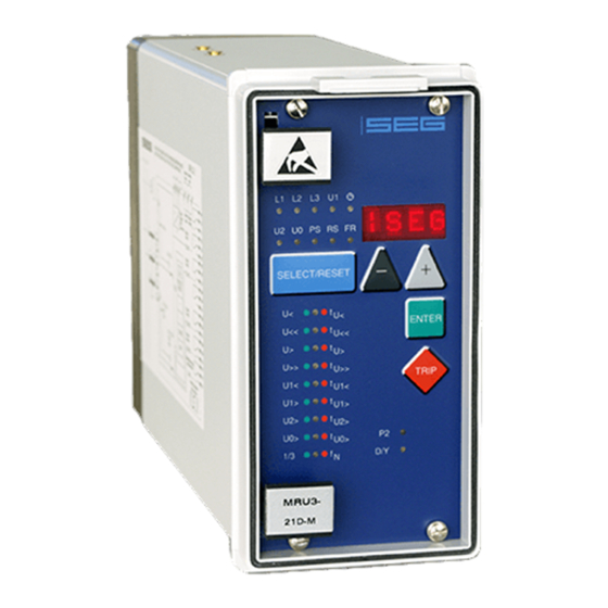
Manual MRU3-2 SEG Electronics GmbH Front plate Figure 3.5: Front plate MRU3-2 DOK-TD-MRU3-2, Rev. B... -
Page 12: Working Principle
SEG Electronics GmbH Manual MRU3-2 4. Working principle Analog circuits The input voltages are galvanic ally insulated by the input transformers. The noise signals caused by inductive and capacitive coupling are suppressed by an analog R-C filter circuit. The analog voltage signals are fed to the A/D-converter of the microprocessor and transformed to digital signals through Sample- and Hold- circuits. -
Page 13: Selection Of Star Or Delta Connection
Manual MRU3-2 SEG Electronics GmbH Selection of star or delta connection All six connections of the input voltage transformers are led to screw terminals. The nominal volt- age of the device is equal to the nominal voltage of the input transformers. Dependent on the appli- cation the input transformers can be connected in either delta or star. -
Page 14: Voltage Supervision
SEG Electronics GmbH Manual MRU3-2 Voltage supervision 4.4.1 1-phase/3-phase supervision The voltage relay MRU3-2 protects electrical generation systems, consumers and appliances in general against over- and/or under voltage. The re-lay is equipped with an independent, 2-step over- (U>, U>>) and under voltage supervision (U<, U<<) with separately adjustable tripping values and de-lay times. -
Page 15: Measuring Principle
Manual MRU3-2 SEG Electronics GmbH 4.4.3 Measuring principle Any rotating three-phase system (original system) can be replaced by three symmetrical systems acc. to the method of the "symmetrical components", a positive sequence system, a negative se- quence system and a zero sequence system. -
Page 16: Negative Sequence System Of A Symmetrical Voltage System
SEG Electronics GmbH Manual MRU3-2 4.4.4 Negative sequence system of a symmetrical voltage system Figure 4.3: Graphical determination of the negative sequence system in a symmetrical system Figure 4.3 shows a symmetrical vector system. As indicated in the calculation the MRU3-2 forms the negative sequence system. -
Page 17: Zero Sequence System
Manual MRU3-2 SEG Electronics GmbH 4.4.6 Zero sequence system To decide whether a vector system is symmetrically, the point, the symmetry has to refer to, is al- ways to be mentioned. Usually this point is the earth potential. When an earth fault occurs in an isolated or compensated grid, it does not influence the relative position of the three voltage vectors to each other, mains operation can be maintained. -
Page 18: Operations And Settings
SEG Electronics GmbH Manual MRU3-2 5. Operations and settings Display Function Display shows Pressed pushbutton Corre- sponding Normal operation Measured operating val- Actual measured value <SELECT/RESET> L1, L2, L3, one time for each value U1, U2, U0 Phasenfolge 123; 321 Transformer ratio of the (SEK) 1.01-6500=prim... -
Page 19: Setting Procedure
Manual MRU3-2 SEG Electronics GmbH Function Display shows Pressed pushbutton Corre- sponding U1<, U1>, U2>, U0> Delta-connection: L1/L2, Tripping values in volt <SELECT/RESET><+><-> L1, L2, L3, L2/L3, L3/L1 one time for each phase U1, U2, U<, symmetrical components: U<<, U>, U1, U2 U>>, U1<,... -
Page 20: System Parameter
SEG Electronics GmbH Manual MRU3-2 System parameter 5.3.1 Display of residual voltage UE as primary quantity (U prim The residual voltage can be shown as primary measuring value. For this parameter the transfor- mation ratio of the VT has to be set accordingly. If the parameter is set to "sec", the measuring val- ue is shown as rated secondary voltage. -
Page 21: Display Of The Activation Storage
Manual MRU3-2 SEG Electronics GmbH Setting v = 50 f = 50 v = 60 f = 60 Rated frequency 50 Hz 50 Hz 60 Hz 60 Hz Influence on voltage none 0,5..1%/Hz none 0,5..1%/Hz measurement (refer to table 5.1) (refer to table 5.1) -
Page 22: Protection Parameters
SEG Electronics GmbH Manual MRU3-2 Protection parameters 5.4.1 1-phase or 3-phase U</U>-tripping Switching-over of the parameter permits selection between 1-phase and 3-phase tripping of the U</U> steps. Keys <+> or <-> are used to change the value and <ENTER> to store it. -
Page 23: Setting Of Baud-Rate (Applies For Modbus-Protocol Only)
Manual MRU3-2 SEG Electronics GmbH 5.4.7 Setting of Baud-rate (applies for Modbus-Protocol only) Different transmission rates (Baud rate) can be set for data transmission via Modbus Protocol. The rate can be changed by push buttons <+> and <-> and saved by pressing <ENTER>. -
Page 24: Date And Time
SEG Electronics GmbH Manual MRU3-2 Date and time 5.6.1 Adjustment of the clock When adjusting the date and time, LED lights up. The adjustment method is as follows: Date : Year Y=00 Month M=01 D=01 Time : Hour h=00... -
Page 25: Indication Of Measuring Values
Manual MRU3-2 SEG Electronics GmbH Indication of measuring values 5.7.1 Measuring indication In normal operation the following measuring values can be displayed. Voltages (LED L1, L2, L3 green) In star connection all phase-to-neutral voltages In delta connection all phase-to-phase voltages ... -
Page 26: Indication Of The Phase Sequence
SEG Electronics GmbH Manual MRU3-2 5.7.5 Indication of the phase sequence The indication refers to the designation of the volt-age input terminals. The sequence can be "123" or "321". Which phase sequence is the correct one depends upon the given case of application. -
Page 27: Additional Funktion
Manual MRU3-2 SEG Electronics GmbH Additional Funktion 5.9.1 Setting procedure for blocking the protection functions The blocking function of the MRU3-2 can be set according to requirement. By applying the aux. voltage to D8/E8, the functions chosen by the user are blocked. Setting of the parameter should be done as follows: ... -
Page 28: Reset
SEG Electronics GmbH Manual MRU3-2 After the assignment mode has been activated, first LED U< lights up green. Now one or several of the four output relays can be assigned to under volt-age element U< as alarm relays. At the same time the selected alarm relays for under voltage element 1 are indicated on the display. -
Page 29: Erasure Of Fault Storage
Manual MRU3-2 SEG Electronics GmbH 5.9.3 Erasure of fault storage To delete the trip store, the push button combination <SELECT/RESET> and <->, has to be pressed for about 3s. The display shows “wait”. Relay function Output relays Display- Corresponding Indication U<... -
Page 30: Relay Testing And Commissioning
SEG Electronics GmbH Manual MRU3-2 6. Relay testing and commissioning The following test instructions should help to verify the protection relay performance before or dur- ing commissioning of the protection system. To avoid a relay damage and to ensure a correct relay operation, be sure that: ... -
Page 31: Checking The Set Values
Manual MRU3-2 SEG Electronics GmbH Checking the set values By repeatedly pressing the push button <SELECT>, all relay set values may be checked. Set value modification can be done with the push button <+><-> and <ENTER>. For detailed information about that, please refer to chapter 4.3 of the description “MR – Digital multifunctional re-lays”. -
Page 32: Secondary Injection Test
SEG Electronics GmbH Manual MRU3-2 Secondary injection test 6.4.1 Test equipment Voltmeter with class 1 or better Auxiliary power supply with the voltage corresponding to the rated data on the type plate Three-phase voltage supply unit with frequency regulation (Voltage: adjustable from 0 to 2 x U ... -
Page 33: Checking The Input Circuits And Measuring Functions
Manual MRU3-2 SEG Electronics GmbH 6.4.3 Checking the input circuits and measuring functions Apply three voltages of rated value to the voltage input circuits (terminals A3 - A8) of the relay. Check the measured voltages, frequency and vector surge on the display by pressing the push but- ton <SELECT/RESET>... -
Page 34: Test Of The Symmetrical Components Values
SEG Electronics GmbH Manual MRU3-2 6.4.4 Test of the symmetrical components values The following tests describe basically the indicating values and voltages of the symmetrical com- ponents with which the measuring functions of the MRU3-2 can be tested. If simultaneously the tripping function is to be tested, the corresponding parameter must be set between the rated volt- age and the theoretical value accept to the table. - Page 35 Manual MRU3-2 SEG Electronics GmbH Phase failure The MRU3-2 is now to be connected with the two phases L2 and L3 and with the neutral conduc- tor. The two phases must be assigned correctly. The measuring input of phase L1 is connected with the star point of the relay in order to prevent interference voltages at the input.
-
Page 36: Checking The Operating And Resetting Values Of The Over/Under Voltage Functions
SEG Electronics GmbH Manual MRU3-2 6.4.5 Checking the operating and resetting values of the over/under voltage functions Apply three voltages with the rated value and gradually increase (decrease) the voltages until the relay starts, i.e. at the moment when the LED U> (or U<) lights up or the voltage alarm output relay (contact terminals D4/E4) is activated. -
Page 37: Primary Test
Manual MRU3-2 SEG Electronics GmbH Primary test Generally, a primary injection test could be carried out in the similar manner as the secondary in- jection test described above. With the difference that the protected power system should be, in this case, connected to the installed relays under test „on line“, and the test voltages should be injected... -
Page 38: Technical Data
SEG Electronics GmbH Manual MRU3-2 7. Technical Data Measuring input circuits Rated data: Nominal voltage 100 V, 230 V, 400 V Nominal frequency 40 - 70 Hz Power consumption in voltage circuit: < 1 VA per phase at U Thermal withstand in... -
Page 39: Setting Ranges And Steps
Manual MRU3-2 SEG Electronics GmbH Setting ranges and steps Function Parameter Setting range Step Pickup tolerance Transformer (sek) 1.01...6500 0.01; 0.02; 0.05; 0.1; prim ratio 0.2; 0.5; 1.0; 2.0; 5.0; 10; 20; 50 Switch group D = DELT/Y = Y... -
Page 40: Parameter For The Fault Recorder
SEG Electronics GmbH Manual MRU3-2 7.3.2 Parameter for the fault recorder Function Parameter Adjustment example Number of recordings (1)*2 x 8 s; (3)*4 x 4 s; (7)*8 x 2 s (50 Hz) (1)*2 x 6.66 s, (3)*4 x 6.66 s, (7)*8 x 1.66 s (60 Savings of the recording at the occurrence P_UP;... -
Page 41: Order Form
Manual MRU3-2 SEG Electronics GmbH 8. Order form Mains decoupling relay MRU3- Standard incl. measuring of the positive phase-sequence, negative phase-sequence and zero phase- sequence system component Rated voltage 100 V 230 V 400 V 19“- rack Housing (12TE) Flash mounting... - Page 42 SEG Electronics GmbH Manual MRU3-2 Setting list MRU3-2 Project: Job.-No.: Function group:= Location:+ Relay code: - Relay functions: Password: Date: All settings must be checked at site and should the occasion arise, adjusted to the object/item to be protected. Setting of the parameters...
- Page 43 Manual MRU3-2 SEG Electronics GmbH Protection parameter Default setting Actualsetting Set 1/Set 2 Set1/Set2 Function Unit 1-phase/3-phase tripping U<>1 U< Pickup value for under voltage element 90/210/360* Tripping delay for under voltage element 0.04 U< U<< Pickup value for under voltage element 80/190/320* <<...
- Page 44 SEG Electronics GmbH Manual MRU3-2 Fault recorder Default Actual Function Unit setting setting Number of recordings Saving of the recording at the occurrence TRIP Time prior to trigger impulse 0,05 Year setting year Y=00 Month setting month M=01 Day setting...
- Page 45 Manual MRU3-2 SEG Electronics GmbH Setting of code jumpers Code jumper Default Actual Default Actual Default Actual settings settings settings settings settings settings Plugged Not plugged No function Code jumper Low/High-range for reset input Low/High-range for blockage input Default settings...
- Page 46 SEG Electronics GmbH reserves the right to update any portion of this publication at any time. Information provided by SEG Electronics GmbH is believed to be correct and reliable. However, SEG Electronics GmbH assumes no responsibility unless otherwise expressly undertaken.
Need help?
Do you have a question about the HighTECH MRU3-2 and is the answer not in the manual?
Questions and answers