Table of Contents
Advertisement
Quick Links
Advertisement
Table of Contents

Related Manuals for Seg MRF3


Summary of Contents for Seg MRF3
- Page 1 MRF3 - Frequency Relay...
-
Page 2: Table Of Contents
Parameter for the fault recorder This manual is valid for software version D01-6.00. 5.5.1 Adjustment of the fault recorder 5.5.2 Type of fault recorder 5.5.3 Number of the fault recordings 5.5.4 Adjustment of trigger occurences 5.5.5 Pre-trigger time (T TB MRF3 04.01 E... -
Page 3: Introduction And Application
Introduction and application Features and characteristics • Microprocessor technology with watchdog The MRF3 is a universal frequency relay and contains • effective active low pass filter for suppressing of the protective functions required by most electrical utili- ties for mains parallel operation of power stations: harmonics, •... -
Page 4: Design
Design Connections Figure 3.1: Connection diagram MRF3 Note: Phase voltages can also be connected to A3/A4 TB MRF3 04.01 E... -
Page 5: Analog Input Circuits
3.1.4 External reset input Refer chapter 5.9.1 3.1.2 Output relays The MRF3 has 5 output relays with change-over con- tacts: Output relay 1: C1, D1, E1 and C2, D2, E2 Output relay 2:... -
Page 6: Fault Recorder
When 1, 3 or 7 recordings are chosen, the corre- Figure 3.3: Standard structure of fault recording sponding number of subranges is reserved in the store. If the store is full, the first-in recording will always be written over by the latest one. TB MRF3 04.01 E... -
Page 7: Parameter Settings
2 Pickup value for the frequency changing speed of the df/dt stage 2 Time difference cum value of the trip counter of the df/dt stage 2 Blocking of frequency measuring Bmin Release of frequency measuring Bmax TB MRF3 04.01 E... -
Page 8: Leds
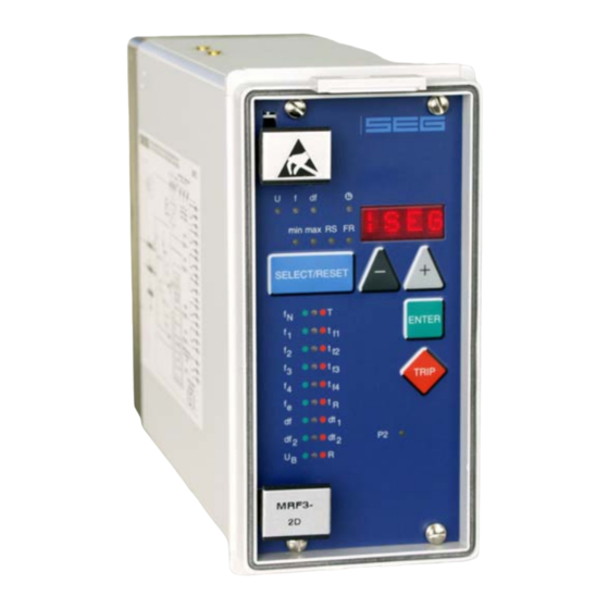
The LED marked with the letters RS lights up green dur- ing setting of the slave address for the serial interface (RS485) of the unit. Figure 3.4: Front plate MRF3 TB MRF3 04.01 E... -
Page 9: Working Principle
Principle of frequency supervision Analog circuits The input voltage is galvanically insulated via the input Frequency relay MRF3 protects electrical generators, voltage transformer. The noise signals caused by the consumers or electrical operating equipment in general influence of inductive and capacitive couplings are against over- or underfrequency. -
Page 10: Measurement Of The Frequency Gradient
The MRF3 can be used for defined load shedding in On account of the above-mentioned disadvantages order to re-stabilise the grid. only the consideration of the average value of the fre-... - Page 11 Application example: f The df/dt function of the MRF3 for load shedding is only active as from an adjustable frequency threshold value f . If the measured system frequency drops be- low f , a time counter is started (adjustment value dt in periods).
-
Page 12: Operation And Settings
EXIT <SELECT/RESET><+><-> LED of blocked green parameters Blocking for the frequency measuring Setting value in Volt <SELECT/RESET><+><-> green yellow The MRF3 is operating with the df/dt function Setting is only possible in case of dt/df trip TB MRF3 04.01 E... - Page 13 Inquire password PSW? <SELECT/RESET>/ <+>/<->/<ENTER> Relay tripped TRIP <TRIP> or fault tripping Secret password XXXX <SELECT/RESET>/ <+>/<->/<ENTER> SEG System reset <SELECT/RESET> for about 3 s only Modbus Protocol Table 5.1: Possibilities for indications by the display TB MRF3 04.01 E...
-
Page 14: Setting Procedure
First the nominal frequency (50 or 60 Hz) has to be then be used as external RESET or BLOCKING inputs. set before unit MRF3 is put into operation. All frequency functions are determined by setting the At setting B_S2 the BLOCKING input (D8/E8) can be nominal frequency, i.e. -
Page 15: Number Of Measuring Repetitions(T)
In order to avoid false tripping of the unit at short volt- age drops of the system voltage or interference volt- f,min ages, MRF3 works with an adjustable measuring repe- 2..49 (T+1)·20 ms tition. When the instantaneous frequency measuring 50..69... -
Page 16: Parameter For Frequency Gradient Supervision Df/Dt At Load Shedding
= 49.2 Hz. Tripping of MRF3 is to follow when a mean frequency gradient 5.4.10 Voltage threshold for frequency of df =1Hz/s is exceeded before the critical fre-... -
Page 17: Setting Of Parity (Applies For Modbus Protocol Only)
Parameter for the fault recorder “Test”. 5.5.1 Adjustment of the fault recorder 5.5.5 Pre-trigger time (T The MRF3 is equipped with a fault recorder (see chap- ter 3.1.5). Three parameters can be determined. By the time T it is determined which period of time prior to the trigger occurence should be stored as well. -
Page 18: Additional Functions
Additional functions 5.7.1 Setting procedure for blocking the protection functions The blocking function of the MRF3 can be set accord- ing to requirement. By applying the aux. voltage to D8/E8, the functions chosen by the user are blocked. Setting of the parameter should be done as follows: •... - Page 19 , tf , tf , dt and dt red as not apply for MRF3. For relays without assignment tripping relays. mode this jumper is used for parameter setting of Definition: alarm relays (activation at pickup or tripping). A form is attached to this description where the setting Definition: requested by the customer can be filled-in.
-
Page 20: Measuring Values
Measuring values 5.8.1 Instantaneous values Min.-/max. measurement of the frequency: Unit MRF3 calculates from each cycle of the mains The indication of the instantaneous measuring values is voltage the instantaneous frequency. These measuring described in the general description "MR - Digital Mul- values are written into the min.-/max.-storage. -
Page 21: Reset
5.9.1 Reset • Normal measuring values are selected by pressing MRF3 has the following 3 possibilities to reset the dis- the <SELECT/RESET> button. play as well as the output relays at jumper position • When then the <-> button is pressed, the latest fault J3 = ON. -
Page 22: Dynamic Behaviour Of The Relay Functions
Short time voltage drop no tripping no tripping no tripping no tripping Table 5.5: Dynamic behaviour of MRF3-Functions * There is a free choice of parameters for the setting (see chapter 5.7.1). TB MRF3 04.01 E... -
Page 23: Relay Testing And Commissioning
(watchdog) is en- relay set values may be checked. Set value modifica- ergized (Contact terminals D7 and E7 closed). tion can be done with the push button <+><-> and <ENTER>. TB MRF3 04.01 E... -
Page 24: Secondary Injection Test
Secondary injection test 6.4.2 Test circuit 6.4.1 Test equipment For testing MRF3 the connection of a voltage source with adjustable frequency is required. Fig. 6.1 shows • Voltmeter and frequency meter with class 1 or better a simple example of a test circuit. For checking the •... -
Page 25: Checking The Input Circuits And Measuring Values
The external blocking input blocks the underfrequency releases. and df/dt functions of the MRF3 which are selected in The reset value for overfrequency must be smaller than the assignment mode (please refer to tab. 5.2 , page the setting value of fx+R, for underfrequency it must be larger than the setting value of fx+R. -
Page 26: Primary Injection Test
For digital relays like MRF3, system. this interval can be substantially longer. This is be-... -
Page 27: Technical Data
Influences on delay time: no additional influences to be measured GL-Approbation: 98776-96HH Bureau Veritas Approbation: 2650 6807 A00 H For additional common data of all MR-relays please refer to manual "MR - Digital Multifunctional relays". TB MRF3 04.01 E... -
Page 28: Setting Ranges And Steps
= 50 Hz for setting f = 60 Hz setting „VARI“: df/dt – measurement for mains decoupling „Setting values“: df/dt – measurement for load shedding schemes Parameters appear with setting "VARI" at overfrequency setting / at underfrequency setting TB MRF3 04.01 E... -
Page 29: Order Form
Order form Frequency relay MRF3- Rated voltage: 100 V 230 V 400 V Housing (12TE): 19“-rack Flush mounting Technical data subject to change without notice! TB MRF3 04.01 E... - Page 30 Blocking of the frequency measurement 10/23/40* Bmin Releasing for the frequency meauring Bmax Slave address of the serial interface *threshold dependent on rated voltage 100 V / 230 V / 400 V **Parameters appear with setting „VARI“ TB MRF3 04.01 E...
- Page 31 Assignment of the output relays: Function Relay 1 Relay 2 Relay 3 Relay 4 Default Actual Default Actual Default Actual Default Actual settings settings settings settings settings settings settings settings pick-up tripping pick-up tripping pick-up tripping pick-up tripping tripping tripping TB MRF3 04.01 E...
- Page 32 Code jumper Low/High-range for Reset input Low/High-range for blockage input Default settings Actual settings Default settings Actual settings Low=plugged High=not plugged This technical manual is valid for Software version number: D01-8.10 (MRF3) Modbus version number: D51-1.10 (MRF3-M) TB MRF3 04.01 E...
Need help?
Do you have a question about the MRF3 and is the answer not in the manual?
Questions and answers