Table of Contents
Advertisement
Quick Links
Advertisement
Table of Contents

Related Manuals for Seg MRM3


Summary of Contents for Seg MRM3
- Page 1 MRM3 Motor Protection Relay –...
-
Page 2: Table Of Contents
Phase Short-Circuit Trip (I>>) and (I>>+Start) 5.4.10 Negative Phase Sequence 5.4.11 Earth Fault Element (I >) 5.4.12 Trip Characteristics for the Earth Fault Element (I >+CHAR) 5.4.13 Tripping Time or Time Factor for the Earth Fault Element (IE>+t>) TB MRM3 07.01 E... - Page 3 6 Notes on Relay Tests and Commissioning Connection of the auxiliary voltage Testing of Output Relays and LEDs Test circuit for MRM3 6.3.1 Checking of Input Circuits and of the Measuring Values 6.3.2 Testing the START-STOP-RUNNING Recognition 6.3.3 Testing the Pick-Up and Disengaging Values 6.3.4...
-
Page 4: Introduction And Application
• Measuring of the phase currents during short-circuit The MRM3 is available with rated currents of 1A or free operation, • Blocking of the individual protective elements or the trip elements can be set freely, •... -
Page 5: Design
Design Connections Figure 3.1: Connection Diagram MRM3 L1.1 L1.2 L2.1 L2.2 L3.1 L3.2 Figure 3.2: Measuring of phase currents and earth current detection Figure 3.3: Measuring of earth current with core-type CT (IE) in Holmgreen connection (IE) This kind of connection can be used where three... -
Page 6: Analog Inputs
High Open <= 60V >= 70V The MRM3 has 5 output relays. Two of these relays with two change-over contacts and three relays with one change-over contact each are used for signalling. The protective functions can be freely allocated except of those for the self-supervision relay. -
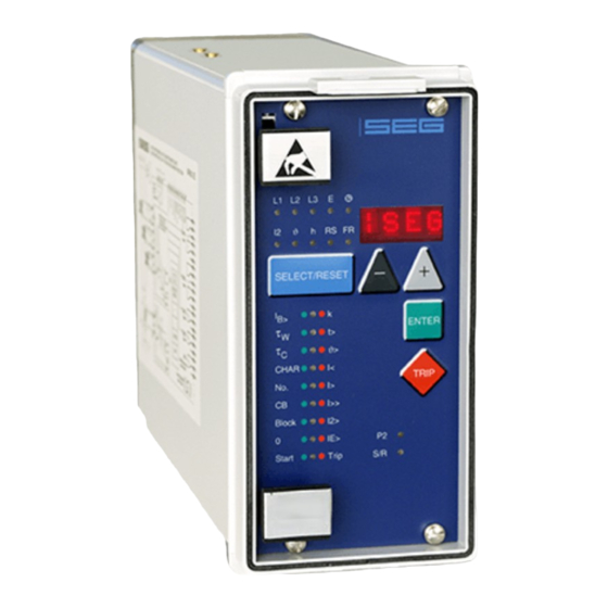
Page 7: Front Plate
Front plate The LEDs ϑ, h, RS and FR on the MRM3 emit a yellow light, all other LEDs are bi-coloured. The LEDs at the left next to the alphanumerical display give a green light during measuring and a red one when a fault signal occurs. -
Page 8: Analog Part
"Hardware-Watchdog". Processor failure is unit. With this micro-controller all tasks are completely signalled by the “Selfsupervision” output relay. digitally processed, from discretization of the measur- ing quantities to protective tripping. Figure 3.7: Block Diagram of Protective Functions TB MRM3 07.01 E... -
Page 9: Working Principle
Working Principle Start Recognition The MRM3 monitors the flow of the current from which the following operational conditions of the motor are gathered. • STOP • START • RUNNING Figure 4.1: Different Start-Up Behaviour of Motors STOP - Condition: START-Condition: If no current can be measured (I <... -
Page 10: Criteria For Blocking The Start
4.1.1 Criteria for Blocking the Start Number of monitored starts : The protective element can either be tied to the thermal The MRM3 is equipped with a flexible supervision image or be manually defined by the number of starts and cycle duration. - Page 11 For this the MRM3 de- tects the average thermal load of the latest starts. With the motor shut down, the start blocking relay is acti-...
-
Page 12: Thermal Image
For the nominal range or the lower load range it has ⋅ to be taken into account that not only the basic accu- racy of the MRM3 has to be considered but also the Note: transformer accuracy. This applies especially for cases... -
Page 13: Operation And Adjustments
= 12, m = 2, s = 12 Slave address of the serial interface 1-32 Chap. 5.6.1 Baud-Rate 1200-9600 Chap. 5.6.2 Parity-Check even odd no Chap. 5.6.3 Table 5.1: Indication Possibilities via the Display Modbus only TB MRM3 07.01 E... -
Page 14: Settting Procedure
5.3.2 Rated -Frequency The FFT-Algorithm used for the data acquisition needs the set point of the rated frequency, i.e. 50 Hz or 60 Hz, for correct digital filtering of the earth current. TB MRM3 07.01 E... -
Page 15: Protection Parameters
(I> + t>) starts to flash after the trip characteristics have changed. By this warning signal the operator is The MRM3 trips if after a successful start the current reminded to adjust the tripping time or time factor to... -
Page 16: Reset Mode For The Trip Characteristics
The current in the negative phase sequence system is turned again. the measure for the load unbalance quantity. The ef- fective value of the current of the negative phase se- is calculated by the MRM3. 5.4.9 Phase Short-Circuit Trip (I>>) and quence system I (I>>+Start) -
Page 17: Element (I E >+Char)
DEFT Definite Time (definite time over- short-circuit currents. In such a case no function of the current protection) MRM3 must initiate tripping. The trip function is then NINV Normal inverse (Type A) allocated to a preceding protective element (e.g. VINV Very inverse (Type B) fuse). -
Page 18: Start Blocking Time (Start+Block+T>)
This example shows that the store was used for more than 8 recordings because store spaces 6, 7 and 8 are used. From this it follows that no. 6 was the eldest recording and no. 4 the latest one. TB MRM3 07.01 E... -
Page 19: Number Of Fault Recordings
Access to the window via push- There is the choice between four different trigger button <SELECT/RESET>. events: P_UP (PickUP) Data saving begins when a general activation is recognised. TRIP Data saving begins when a general trip is recognised. TB MRM3 07.01 E... -
Page 20: Additional Functions
Earth current element NO_B NO_B ; PR_B ; TR_B > red tCBFP CB failure protection NO_B NO_B ; BLOC CB green Trip External trip NO_B NO_B ; BLOC Trip red Table 5.4: Default Setting of the Blocking Functions TB MRM3 07.01 E... -
Page 21: Allocation Of The Reset Functions
AUTO HAND ; AUTO > red / t> red tCBFP CB failure protection AUTO HAND ; AUTO CB green Trip External trip AUTO HAND ; AUTO Trip red Table 5.5: Default setting of the Reset Functions TB MRM3 07.01 E... -
Page 22: Allocation Of The Output Relays
5.9.3 Allocation of the Output Relays The MRM3 has five output relays. The fifth output relay By pressing push-buttons <+> and <-> all possible combinations can be realised. The selected allocation is an alarm relay for the self-supervision and its alloca- can be saved by <ENTER>... -
Page 23: Measuring Value And Fault Indications
• Number of motor starts (LED No. green) • Time until tripping in min. (LED Trip/t> red) • Remaining time of start blocking in min. (LED Start/Block green and t> red) • Date and time (LED green) TB MRM3 07.01 E... -
Page 24: Units Of The Displayed Measuring Values
All fault events acquired by the relay are optically indi- The fault memory can be cleared by pressing the button cated on the front cover. For the MRM3 the four LEDs combination <SELECT/RESET> and <-> for about 3s. In (L1, L2, L3, I2; E) and the functional LEDs (ϑ>; I >;... -
Page 25: Reset
5.11 Reset 5.12 Digital Inputs The MRM3 offers the following three ways to reset the 5.12.1 Parameter Set Changeover Switch displayed indications as well as the output relay. When voltage is applied to this input it is changed over • Manual reset to the other parameter set. - Page 26 Release of self-test relay Pick-up of all output relays Test of all LEDs <Select/ |SEG Finish the test, Reset> Output relays return to their cur- rent operational state * If possible please state when writing to us. TB MRM3 07.01 E...
- Page 27 Test circuit for MRM3 For testing the MRM3 relays only one power source is necessary. Figure 6.1 shows a simple example of a single-phase testing circuitry with controllable power source for testing the unit. Figure 6.1: Test circuit 6.3.1 Checking of Input Circuits and of the...
- Page 28 MRM3 was triggered (see chapter under real conditions. Some of the tests could be simpli- 5.4.15). To meet these requirements, the test source...
- Page 29 Many functions of the MRM3 can be checked during normal operation of the system due to the efficient fault and measuring value in- dications.
- Page 30 0.9 < f / f < 1.1; <0.2% Measuring errors at higher frequencies: 70Hz – 400Hz < 0.2% / Hz Influences on delay time: no additional influences can be measured For further technical data see the general description „MR-Multifunctional Relay“. TB MRM3 07.01 E...
- Page 31 M=01...12 Month 1 month D=01...31* Day (* depends on month) 1 day h=00... 23 Hour 1 hour m=00...59 Minute 1 minute s=00... 59 Second 1 second Parameter set changeo- SET1 active parameter set ver switch SET2 TB MRM3 07.01 E...
- Page 32 ±3% of the setting During running value or ±10mA EXIT Step switched off Trip delay I>>+t> 0,04...10 Trip delay in s 0.02; 0.05; 0.1; 0.2 s ±3% of the setting EXIT Warning only value or ±20ms TB MRM3 07.01 E...
- Page 33 Characteristic parameter rent measuring value or ±20ms EXIT Warning only (See EN 60255-3) Table 7.1: Setting ranges and steps 7.3.5 Circuit breaker failure protection Parameter Setting range Step Tolerance CB+t> 0.1...2.00 CB time EXIT Step switched off TB MRM3 07.01 E...
- Page 34 7.3.9 Interface parameter Parameter LED * Setting range Step Tolerance 1 - 32 Slave-Adress Baud-Rate 2400 4800 9600 */** Parity even even*/** odd* none* * selectable when Modbus Protocol is used ** fixed setting for RS485 TB MRM3 07.01 E...
- Page 35 At actuation TRIP At trip A_PI After actuation TEST Test recording with button <+> and <-> Pre-trigger time 0,05...8,00 Duration of the previous event S * All given times refer to 50 Hz (60 Hz in brackets) TB MRM3 07.01 E...
- Page 36 − p=0.2 p=0.3 p=0.4 p=0.5 0.08 p=0.6 0.06 p=0.7 0.04 p=0.8 0.02 p=0.9 0.01 1.25 1.75 2.25 Figure 7.1: Trip Characteristics for Various Initial Load Factors p TB MRM3 07.01 E...
- Page 37 [min] 100,0 10,0 τ = 180 min τ = 100 min τ = 10 min τ = 1 min τ = 0.5 min I / I Figure 7.3: Limitation of tripping time bei 6 x I TB MRM3 07.01 E...
- Page 38 RXIDG – characteristics − × × > Where: Tripping time > Time multiplicator Fault current Setting value of the current natural logarithm TB MRM3 07.01 E...
- Page 39 Figure 7.6: Extremely inverse (Type C) 10000 1000 1000 I> I> 20.0 t[s] t[s] 10.0 10.0 0.05 0.06 5 6 7 8 9 10 5 6 7 8 9 10 Figure 7.5: Very Inverse (Type B) Figure 7.7: Long time inverse TB MRM3 07.01 E...
- Page 40 0.05 5 6 7 8 9 10 Figure 7.9: RXIDG-characteristic Output relays Contacts: 2 change-over contacts for relays 1 and 2; 1 change-over contact for relays 3 - 4 This information is subject to technical alterations!! TB MRM3 07.01 E...
- Page 41 Phase current rated current Earth fault current Without earth current element rated current Housing (12TE) 19“-rack door installation Communication protocol RS485 Pro Open Data; Modbus RTU * Leave box empty, if option is not desired TB MRM3 07.01 E...
- Page 42 Setting list for MRM3 Project: SEG-Job.-No.: Functional group: = Location: + Relay code: - Relay functions: Password: Date: All settings have to be checked at site and perhaps adjusted to the object to be protected. Date and time settings Funktion...
- Page 43 Time period prior to the trigger impulse 0.05 Interface parameters Function Default set- Actual setting ting Slave Address of the serail interface Baud rate of the serial interface 9600 Parity check of the serial interface even *only with Modbus Protocol TB MRM3 07.01 E...
- Page 44 Load unbalance trip AUTO AUTO IE> Earth current alarm AUTO AUTO IE> + t> Earth current trip AUTO AUTO CB failure protection AUTO AUTO Trip External trip AUTO AUTO *AUTO = Automatic Reset; HAND = Manual Reset TB MRM3 07.01 E...
- Page 45 I2> Trip IE> IE> Alarm IE>+t> IE> Trip CB failure protection Trip Ext. trip, undelayed Trip + t> Ext. trip, delayed Start + Start blocking Block Start Motor is starting Motor is running Start+t> Excessive start-up time TB MRM3 07.01 E...
- Page 46 Ext. trip, delayed Plugged-in D8 / C8 Reset function Plugged-in D8 / E8 Blocking function Plugged-in This technical description applies as from the use of Software Version D01-1.00 MRM3-IE MRM3-I Modbus Protocol Software Version D51-1.00 MRM3-IE-M MRM3-I-M TB MRM3 07.01 E...
Need help?
Do you have a question about the MRM3 and is the answer not in the manual?
Questions and answers
Esquema de ligação
The wiring diagram for the SEG MRM3 includes connections for phase currents and earth current detection. It consists of terminals for three-phase current transformers (CTs) and an earth current transformer (IE) in different configurations.
1. Phase Current Measurement:
- Terminals L1, L2, L3 for phase connections.
- Terminals B3, B4, B5, B6, B7, B8 for CT connections.
- Each phase has corresponding P1, S1, I1, P2, S2 terminals.
2. Earth Current Measurement:
- Terminal B1 (IE) for earth current detection.
- Can use a core-type CT in a Holmgreen connection.
3. Common Reference Point:
- Terminal D8 as a common reference for digital inputs.
For a detailed view, refer to Figure 3.1 (Connection Diagram), Figure 3.2 (Measuring of phase currents and earth current detection), and Figure 3.3 (Measuring of earth current with a core-type CT).
This answer is automatically generated