Table of Contents
Advertisement
Quick Links
Advertisement
Table of Contents

Related Manuals for Seg XRW1-4


Summary of Contents for Seg XRW1-4
- Page 1 XRW1-4 Mains decoupling relay for wind power systems...
-
Page 2: Table Of Contents
Parameter setting of over- and under- Power supply voltage supervision Inputs, blockage and reset 6.2.2 Setting of nominal frequency System data and test specifications 6.2.3 Number of measuring repetitions (T) Relay case for frequency functions Order form TB XRW1-4 04.01 E... - Page 3 Because of combination of three protectional functions vision in one device. • Voltage supervision each with four step under-/ and in one device the XRW1-4 is a very compact mains decoupling device. Compared to the standardly used overvoltage detection • Frequency supervision with three step under-/ or single devices it has a very good price/performance ratio.
-
Page 4: Output Relays
The blocking function can be set according to require- ment. By applying the auxiliary voltage to C1/C1L or The XRW1-4 has 5 output relays. One trip relay with C1/C1H, the previously set relay functions are two changeover contacts. One alarm relay with two blocked (refer to 4.7). -
Page 5: Data Communication
XRW1-4 relay is provided with a serial interface RS485. Simplified and fast reading and changing of parameters and measuring values can be achieved by HTL/PL-Soft4. The XRW1-4 can be connected to other units of the or the H via interface. If ROFESSIONAL... -
Page 6: Front Plate
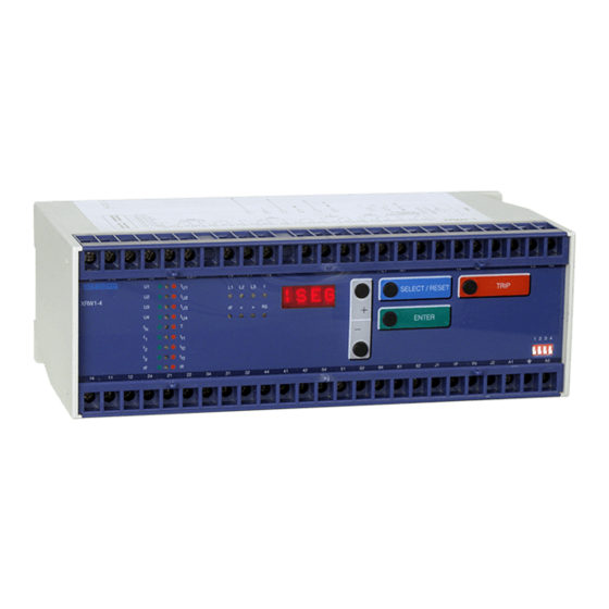
Front plate 3.2.1 Indication- and operation elements The front plate of the XRW1-4-protection relay com- prises the following operation and indication elements: • Alphanumerical display (4 Digits) • Push buttons for setting and other operations • LEDs for measured value indication and setting Figure 3.4: Front plate XRW1-4... -
Page 7: Display
<+>/<->/<ENTER> Relay tripped TRIP <TRIP> or fault tripping Secret password input XXXX <SELECT/RESET>/<+>/<-> /<ENTER> LED blinking after excitation NOFL/FLSH <SELECT/RESET><+><-> SEG System reset <SELECT/RESET> for about 3 s Table 3.1: possible indication messages on the display TB XRW1-4 04.01 E... -
Page 8: Leds
The LED marked with letters RS lights up during setting of the slave address of the device for serial data com- munication. 3.2.4 Front plate XRW1-4 Figure 3.5: Front plate XRW1-4 TB XRW1-4 04.01 E... -
Page 9: Parameter Settings
2 - 64 < voltage threshold value for frequency and df/dt element 20 - 400 LED blinking after excitation NOFL/FLSH Slave address of the serial interface 1 - 32 Table 3.2: Sequence of parameter setting TB XRW1-4 04.01 E... -
Page 10: Working Principle
Digital circuits phases are decisive for energizing. The essential part of the XRW1-4 relay is a powerful Basic for this elements is the RMS of the voltage fun- damental. microcontroller. All of the operations, from the analog digital conversion to the relay trip decision, are carried out by the microcontroller digitally. -
Page 11: Selection Of Star Or Delta Connection
4.3.1 Selection of star or delta connection Principle of frequency supervision All connections of the input voltage transformers are led The frequency element of XRW1-4 protects electrical to screw terminals. The nominal voltage of the device is generators, consumers or electrical operating equip- equal to the nominal voltage of the input transformers. - Page 12 The total switching off time at mains failure is usually approx. 100 ms (T = 4) depending on the set- ting. TB XRW1-4 04.01 E...
-
Page 13: Voltage Threshold Value For Frequency
Table 4.1: Dynamic behaviour of XRW1-4 functions Blocking function set in compliance with require- ments: The XRW1-4 has an external blocking input. By apply- ing the auxiliary voltage to input C1/C1L or C1/C1H, the requested protection functions of the re- lay are blocked. -
Page 14: Operation And Setting
(see 5.4.2). The <TRIP>-push button is used to test the output relay circuits both for tripping and signalling. During normal operation it is also interlocked by means of the pass- word identification. TB XRW1-4 04.01 E... -
Page 15: Indication Of Measuring Values And Fault Data
5.1.1 Indication of measuring values and fault data Indication in faultless condition In normal operation the display always shows |SEG. After pressing the push button <SELECT/RESET> the display switches cyclically to the next measuring value. After the measuring values had been indicated the set- ting parameters are displayed. -
Page 16: Dip Switches
DIP switches Dip switch 3 OFF: On the front plate of the XRW1-4-relay there are DIP switches to preset the following functions: All output relays will be reset automatically after the • Password programming fault has been rectified, (e.g. when the fault current is •... -
Page 17: Reset
Apply dip switch 1. After power on and pressing any <ENTER> then a password "-E+S" means pressing push buttons push button, the relay XRW1-4 inquires for a new password. The text "PSW?" appears on the display. according to the follwing sequence: <->... -
Page 18: Relay Setting Principle
5.5.1 Setting of default parameters reset inputs, however, has to be defined by taking the supply voltage into account. The following two different Setting of the XRW1-4 default parameters can be done operating thresholds are available: • Low-range threshold U ≥10 V;... -
Page 19: Parameter Settings
Hz/s few measurements in good range. The setting can be measuring repetition for df/dt in periods separately adjusted for the tripping stages t U1< U4< , using the <+> and <-> keys. U1> U4> TB XRW1-4 04.01 E... -
Page 20: Setting Of Nominal Frequency
First the nominal frequency (50 or 60 Hz) has to be The frequency supervision of XRW1-4 has three fre- correctly set before unit XRW1-4 is put into operation. quency elements independent from each other. Acc. to All frequency functions are determined by setting the setting the pickup value above or below the nominal nominal frequency, i.e. -
Page 21: Parameter Setting Of Frequency Gradient
= rated frequency in Hz = inertia time constant of The blocking function of the XRW1-4 can be set ac- the generators cording to requirement. By applying the aux. voltage to ∆P = per unit power deficit with... -
Page 22: Indication Of Measuring Values
Min./max. frequency measuring : The XRW1-4 ascertains the actual frequency from each cycle of the system voltage. These measuring values are entered into the min./max. storage. The latest en- tered min./max. -
Page 23: Fault Memory
Fault memory When the relay is energized or is energized or trips, all Recorded fault data: fault data and times are stored in a non-volatile memory manner. The XRW1-4 is provided with a fault value re- Measuring Displayed value Correspond- corder for max. -
Page 24: Relay Testing And Commissioning
As relay input energizing quantities, three phase volt- "TRIP" on the display and LED L1, L2, L3 and U< light ages should be applied to XRW1-4 relay input circuits. up red). An undervoltage condition has been detected Depending on the system conditions and the voltage... -
Page 25: Secondary Injection Test
• Switching device • Test leads and tools 7.4.2 Example of test circuit For testing of the XRW1-4 relay, a three phase voltage source with adjustable voltage and frequency is re- quired. Figure 7.1 shows an example of a three-phase test circuit energizing the XRW1-4 relay during test. -
Page 26: Checking The Input Circuits And Measuring Functions
Because the XRW1-4 relay measures only the fundamental component of the input signals, the har- Note: monics will be rejected by the internal DFFT-digital fil- Due to frequency changes df/dt tripping can occur ter. -
Page 27: Checking The Relay Operating Time Of
Because of its powerful combined indicating and 50 Hz to 51.4 Hz within 2 s (+0.7 Hz/s). If the fre- measuring functions, the XRW1-4 relay may be tested quency ramp is set from 50 Hz to 49.4 Hz within 2 s in the manner of a primary injection test without extra (0.3 Hz/s), there must not be any tripping. -
Page 28: Maintenance
For digital relays like XRW1-4, this interval can be substantially longer. This is because: • the XRW1-4 relays are equipped with very wide self- supervision functions, so that many faults in the relay can be detected and signalised during service. Im-... -
Page 29: Technical Data
20% of the 5th harmonic <0.05% per percent of the 5th harmonic Influences on frequency measuring: Aux. voltage: in the range 0.8 <U <1.2 no additional influences to be measured Frequency: no influences Influences on delay time: no additional influences to be measured TB XRW1-4 04.01 E... -
Page 30: Setting Ranges And Steps
(LED f+ 20...400 V measuring or <0.3% U Serial Interface 1 - 32 Table 7.1: Setting ranges and steps At 50 Hz rated frequency At 60 Hz rated frequency min. time delay; see chapter 6.2.5 f,min TB XRW1-4 04.01 E... -
Page 31: Output Relays
Current consumption 1 mA DC bei 24 V High-range: ≥70 V ≤60 V For rated voltages 100 V, 110 V, 125 V, 220 V, 230 V Current consumption 1.5 mA DC 270 V or 11.0 mA AC TB XRW1-4 04.01 E... -
Page 32: System Data And Test Specifications
10 V/m Surge immunity test as per EN 61000-4-5: EN 61000-4-5: 4 kV Radio interference suppression test as per EN 55011: limit value class B Radio interference radiation test as per EN 55011: limit value class B TB XRW1-4 04.01 E... -
Page 33: Relay Case
Technical data subject to change without notice! Relay case Relay XRW1-4 is designed to be fastened onto a DIN-rail acc. to DIN EN 50022, the same as all units of the ROFESSIONAL The front plate of the relay is protected with a sealable transparent cover (IP40). -
Page 34: Order Form
RSC2-485-232-1 Interface adapter RS232 and RS485 (with galvanical decoupling) Important: For supplying the interface adapter needed: Plug-in power supply for interface transformer RSC2-NT1-230 230 V 50/60 Hz with german safety plug Diagnosis- and parameterizing software HTL/PL-Soft4 TB XRW1-4 04.01 E... - Page 35 3 pickup value for rate of change of frequency Hz/s (dt/dt) in measuring repetition for df/dt periods < voltage threshold value for frequency or df/dt) LED blinking after excitation FLSH Slave address of the serial interface TB XRW1-4 04.01 E...
- Page 36 Setting of dip switches Dip switch 1 (PSW) Default Actual Default Actual Default Actual Default Actual setting setting setting setting setting setting setting setting no function This technical manual is valid for software version number: D04-7.40 TB XRW1-4 04.01 E...
Need help?
Do you have a question about the XRW1-4 and is the answer not in the manual?
Questions and answers