Table of Contents
Advertisement
Quick Links
High performance
in a compact unit
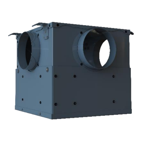
Mechanical Extract Ventilation
Installation, maintenance & user manual
Applicable to the following airstream ACE models:
PRODUCT CODE
AS 92-ACE-H-125
AS 92- ACE-H-204
AS 92- ACE-H-075
AS 92-ACE-125
AS 92- ACE-204
AS 92- ACE-075
DESCRIPTION
airstream Ø125 connection c/w Integral Humidistat
airstream 204 x 60connection c/w Integral Humidistat
airstream Ø75 connection c/w Integral Humidistat
airstream Ø125 connection
airstream 204 x 60connection
airstream Ø75 connection
V1 13.04.22 UK
brookvent.co.uk
Advertisement
Table of Contents

Related Manuals for BrookVent AS 92-ACE-H-125


Summary of Contents for BrookVent AS 92-ACE-H-125
- Page 1 Mechanical Extract Ventilation Installation, maintenance & user manual Applicable to the following airstream ACE models: PRODUCT CODE DESCRIPTION AS 92-ACE-H-125 airstream Ø125 connection c/w Integral Humidistat AS 92- ACE-H-204 airstream 204 x 60connection c/w Integral Humidistat AS 92- ACE-H-075 airstream Ø75 connection c/w Integral Humidistat AS 92-ACE-125 airstream Ø125 connection...
-
Page 2: Table Of Contents
Safety ..........................3 Specifications/ Dimensions ....................4 Installation .......................... 9 Ductwork and Connections ....................11 Electrical Connections/ Wiring ..................12 Controls and Settings ....................... 14 Maintenance........................22 User Operation ......................... 23 Trouble Shooting ......................26 V1 13.04.22 UK brookvent.co.uk 1/29... -
Page 3: Introduction
In the instance of a defect, Brookvent may repair the product, replace the product free of charge or refund the cost of the product at Brookvent’s own discretion. In terms of installation, operation and maintenance please follow all instructions provided. -
Page 4: Safety
The unit is only suitable for 230 VAC/50Hz electric mains. ▪ This unit must be earthed. ▪ Never modify the fan or electronics, all repairs must be conducted by Brookvent. ▪ Never connect the power if electronics cover is not fitted. ▪... -
Page 5: Specifications/ Dimensions
Specifications/ Dimensions 3.01 Ø125 connection H 378mm x W 354mm x D 278mm 3.02 204 x 60 connection H 374mm x W 368mm x D 239mm V1 13.04.22 UK brookvent.co.uk 4/29... - Page 6 3.03 Ø75 connection H 398mm x W 398mm x D 251mm Duct Connections Standard Configuration: Extract from House Outside Exhaust to Outside V1 13.04.22 UK brookvent.co.uk 5/29...
- Page 7 Communication error indication. • Installation: Wall, Ceiling or Floor Mount Standards: Fully complies with Building Regulations for UK & Ireland SAP Appendix Q Listed | Energy Savings Trust Best Practice | CE |UKCA Guarantee Period: 2 Years V1 13.04.22 UK brookvent.co.uk 6/29...
- Page 8 Kitchen + 4 Wet 100 % 0.28 Room Variable Kitchen + 5 Wet 100 % 0.33 Room Variable Kitchen + 5 Wet 100 % 0.41 Room Variable SAP 2012 (See SAP - PCDB for further details) http://www.ncm-pcdb.org.uk/sap/ V1 13.04.22 UK brookvent.co.uk 7/29...
- Page 9 29.6 23.1 58.3 49.1 Open Extract 58.3 58.5 47.5 39.5 35.5 30.8 63.2 70.2 64.9 Speed Duct 43.6 Breakout 45.5 44.3 49.4 36.2 34.4 34.4 27.6 63.7 53.4 Breakout based on hemispherical propagation at 3m V1 13.04.22 UK brookvent.co.uk 8/29...
-
Page 10: Installation
Secure the duct in place with self-tapping screws (pilot hole may need to be drilled) or metal banding and jubilee clips. 4.12 CEILING MOUNT Fig. 1 Please ensure that this method of fixing is suitable for the mounting surface and that it can safely bear the load. V1 13.04.22 UK brookvent.co.uk 9/29... - Page 11 The unit should be attached to the Floor, as shown, mounted on a raised plinth. (Fig.1). 4.11 WALL MOUNT Fig. 3 Please ensure that this method of fixing is suitable for the mounting surface and that it can safely bear the load. V1 13.04.22 UK brookvent.co.uk 10/29...
-
Page 12: Ductwork And Connections
300mm and kept taut as per the Part F Domestic Compliance Guide. The spigots on the Brookvent airstream ACE systems are suitable for connection to Ø125mm round pipe 204x60 rectangular duct or Ø75 semi rigid duct. -
Page 13: Electrical Connections/ Wiring
The switch wires SW1 and SW2 are used to boost or NEUTRAL (BLUE) purge the system. When a live 230v signal is applied, EARTH (GREEN & YELLOW) the Auto Boost/purge function will be triggered. BOOST (BLACK) PURGE (GREY) Green Yellow Black V1 13.04.22 UK brookvent.co.uk 12/29... - Page 14 5.1 Wiring Schematic Fig 4 Fig 5 V1 13.04.22 UK brookvent.co.uk 13/29...
-
Page 15: Controls And Settings
To enter Set Up; Press and hold the SET key until the centre LED flashes green. This means that the trickle speed can now be set. Using a small flat screwdriver adjust the potentiometer up or down until the required airflow has been achieved. V1 13.04.22 UK brookvent.co.uk 14/29... - Page 16 (I.e. Trickle) and an increased speed to be set (I.e. Boost) that operates by the pressing the centre button on the wall controller once (colour changes to blue) or when the Sw1 switch wire is triggered by a 230v boost signal such as a Wall Switch or Passive Infrared Sensor. V1 13.04.22 UK brookvent.co.uk 15/29...
- Page 17 For the required airflow rates refer to the design specification for the property and or refer to local Building Regulations and /or guidelines. If further guidance is required on the commissioning process, please contact Brookvent directly. Mode LED Legend...
- Page 18 If the Adjustment is moved the mode LED The currently stored stops flashing and the new value is saved Humidity Value with the next press of the set button. Range 35%-100% Holding the centre button exits the setup process. V1 13.04.22 UK brookvent.co.uk 17/29...
- Page 19 Purge can be set with the next press of the set Range 20%-100% button. Holding the centre (default 100%) button exits setup process. Above example is set to 85% on Purge. V1 13.04.22 UK brookvent.co.uk 18/29...
- Page 20 Range 35%-100% button. Holding the centre button exits setup process. The unit will enter boost mode when the humidity sensor reads the set level of humidity. Above example is set to 70% Humidity. V1 13.04.22 UK brookvent.co.uk 19/29...
- Page 21 Flashing Blue LED indicates that the boost signal has been switched off and the unit has remained in boost due to the over-run timer (if set). V1 13.04.22 UK brookvent.co.uk 20/29...
- Page 22 60mins due to calibration. 6.4 Boost Over-Run Timer The Brookvent airstream ACE system comes with an adjustable automatic boost over-run timer of up to 100mins (default 1 min). The Grey ‘switch wire’ on the airstream ACE systems (See section ‘5.0 Electrical Connections/ Wiring’) is used to boost the system.
-
Page 23: Maintenance
1. Ensure that all power supplies to the unit are isolated including the two switched live cables that may be fed from different circuits. 2. Remove the 4 screws (A) at either side of the unit and remove panel (B). V1 13.04.22 UK brookvent.co.uk 22/29... -
Page 24: User Operation
▪ loose over time and are kept sufficiently tight. User Operation The Brookvent airstream ACE is an extremely compact and highly efficient Mechanical Extract Ventilation (MEV/CMEV) system, specifically designed for smaller dwellings and apartments with restricted space. The system should be run continuously 24 hours a day and should only be disconnected by a competent person during service or maintenance. - Page 25 *The items detailed above are examples of the types of Automatic Control Options that are typically used in conjunction with the Brookvent airstream ACE* V1 13.04.22 UK brookvent.co.uk...
- Page 26 (Please note that the airstream ACE system has a optional boost overrun time of 0-100mins). *The items detailed above are examples of the types of Manual Control Options that are typically used in conjunction with the Brookvent airstream ACE* V1 13.04.22 UK brookvent.co.uk...
-
Page 27: Trouble Shooting
The fan is drawing more or less power than expected indicating that the fan may have failed. Contact a maintenance engineer. Communication between controller and the unit has failed during set up. V1 13.04.22 UK brookvent.co.uk 26/29... - Page 28 After a short delay the ring will flash yellow, and all the other LEDs will light solid yellow. The unit will then reset. Should either of the above not resolve the issue please contact Brookvent. The system is constantly in Boost? New houses can be quite damp with items drying out;...
- Page 29 Notes Customer Support V1 13.04.22 UK brookvent.co.uk 28/29...
- Page 30 At Brookvent we pride ourselves on providing Gold Standard after sales and support to all customers. Please feel free to contact one of our specialist team about any query you may have, and we will be more than happy to assist you.
Need help?
Do you have a question about the AS 92-ACE-H-125 and is the answer not in the manual?
Questions and answers