Advertisement
Heat Recovery Ventilation
Applicable to aircycle 1.1/1.2
(Ws - For Wall Mounting with In-built Control & Summer Bypass)
Installation and Maintenance
Instructions for the Installer.
Please refer to the User Manual for instructions on how to operate
the system
aircycle 1.1/1.2 – In-built Control & SB
Last Updated 02-01-13
Page 1 of 14
Advertisement
Table of Contents

Related Manuals for BrookVent Aircycle 1.1


Summary of Contents for BrookVent Aircycle 1.1
- Page 1 (Ws - For Wall Mounting with In-built Control & Summer Bypass) Installation and Maintenance Instructions for the Installer. Please refer to the User Manual for instructions on how to operate the system aircycle 1.1/1.2 – In-built Control & SB Last Updated 02-01-13 Page 1 of 14...
-
Page 2: Table Of Contents
Introduction ........................3 Safety ..........................4 Specifications ........................5 Installation .......................... 8 Electrical Connections/ Wiring ..................11 Fan Speed Control......................12 Maintenance ........................13 Commissioning ........................14 aircycle 1.1/1.2 – In-built Control & SB Last Updated 02-01-13 Page 2 of 14... -
Page 3: Introduction
‘habitable rooms’ such as bedrooms, dining rooms and living rooms. Model Variations This installation manual refers to the Brookvent aircycle 1.1 and pertains to the following models: aircycle 1.1/1.2 Ws •... -
Page 4: Safety
Never touch the appliance with wet hands. • The unit is only suitable for 230 VAC/50Hz electric mains. • Never modify the fan or electronics, all repairs must be conducted by Brookvent. • Never connect the power if electronics cover is not fitted. •... -
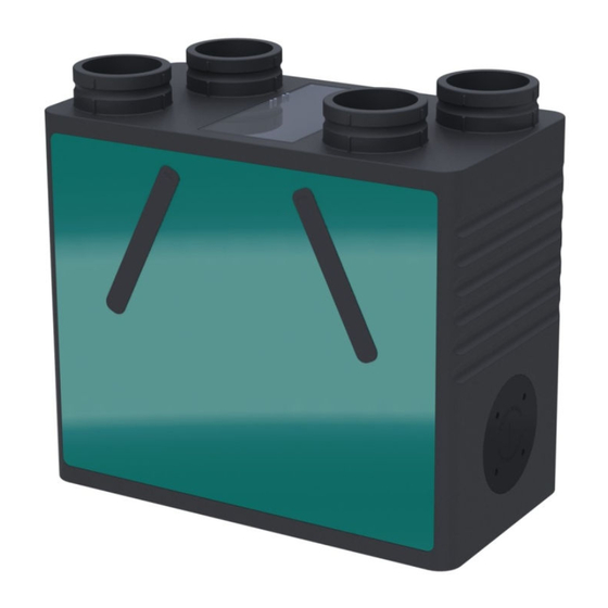
Page 5: Specifications
Specifications Front aircycle 1.1/1.2 – In-built Control & SB Last Updated 02-01-13 Page 5 of 14... - Page 6 Fully complies with Building Regulations for UK & Ireland SAP Q Eligible Specific Fan Power: From 0.7 w/l/s Heat Recovery: Up to 90% efficiency SAP Appendix Q Results www.sap-appendixq.org.uk/documents/Brookvent_Aircycle_MVHR_BP_.pdf aircycle 1.1/1.2 – In-built Control & SB Last Updated 02-01-13 Page 6 of 14...
- Page 7 Airflow: Pressure/ Performance Curve Airflow Performance Curve: aircycle 1.1/1.2 – In-built Control & SB Last Updated 02-01-13 Page 7 of 14...
-
Page 8: Installation
Mounting The aircycle 1.1/1.2 Ws is designed for Wall Mounting only. The unit should be attached the to the wall as shown using the wall bracket provided, please ensure the mounting surface can safely bear the load of the unit using suitable screw fixings. - Page 9 If flexible ducting is required, it should be kept to an absolute minimum of 300mm and kept taut as per the Domestic Compliance Guide (Part F: Eng and Wales 2010) The spigots on the Brookvent aircycle 1.1/1.2 systems are suitable for connection to 125mm diameter round pipe.
- Page 10 HRV systems generate considerable amounts of moisture due to their high Heat Recovery Efficiency; this moisture must be drained from the system. The aircycle 1.1/1.2 is supplied complete with a centralised drainage connection on the bottom of the unit. The condensate drain should incorporate a “P Trap” or equivalent, as shown, before being discharged into the waste drainage system of the dwelling.
-
Page 11: Electrical Connections/ Wiring
HRV unit and should be clearly marked as the disconnecting device for the HRV Unit. Connecting to Mains: The aircycle 1.1/1.2 unit comes pre-wired with 1m length of 4-core cable, which should be connected into a fan-isolation switch. In turn a 3-core mains cable should be used to connect to a 5A fused spur, which should be located close to the unit. -
Page 12: Fan Speed Control
Boost 6.1 Tempering Summer Bypass The Tempering Summer Bypass, unique to Brookvent, operates on a linear scale between 20 Degrees Celsius (No Summer Bypass) and 27 Degrees Celsius (Full Summer Bypass); gradually increasing the amount of air directed around the Heat Recovery Core as the temperature of the extract air from the home rises thus comfortably regulating the indoor air temperature during warmer months. -
Page 13: Maintenance
In new build properties it may be prudent to check/ change your filters after the first 3 months of occupancy depending on the amount of residual ‘building dust’ present within the property aircycle 1.1/1.2 – In-built Control & SB Last Updated 02-01-13... -
Page 14: Commissioning
For the required airflow rates refer to the design specification for the property and or refer to Building Regulations (Part F) If further guidance is required on the commissioning process please contact BROOKVENT directly using the information provided below. BROOKVENT...
Need help?
Do you have a question about the Aircycle 1.1 and is the answer not in the manual?
Questions and answers