Table of Contents
Advertisement
Quick Links
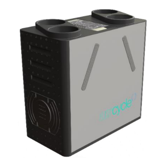
Heat Recovery Ventilation
Installation, maintenance & user manual
Applicable to the following aircycle 1.3 & 1.3+ models:
aircycle MVHR
Product Type
c/w Humidistat, Bypass - Wall Mount
c/w Humidistat, Bypass - Floor Mount
c/w Humidistat, Bypass - Ceiling Mount
Product codes shown refer to "Standard" duct configuration.
Add "V" to the end of each product code for an "inverted duct configuration.
Digital Controller
1.3 DIGITAL RANGE
aircycle 1.3
Digital Control
AS 90-0103-WDS-01
AS 90-0103-FDS-01
AS 90-0103-CDS-01
AM 90-02-301
aircycle 1.3+
Digital Control
AS 90-0103P-WDS-01
AS 90-0103P-FDS-01
AS 90-0103P-CDS-01
V. 1.3-05-08-19
brookvent.co.uk
Advertisement
Table of Contents

Related Manuals for BrookVent 90-0103-WDS-01


Summary of Contents for BrookVent 90-0103-WDS-01
- Page 1 MVHR aircycle 1.3 aircycle 1.3+ Product Type Digital Control Digital Control c/w Humidistat, Bypass - Wall Mount AS 90-0103-WDS-01 AS 90-0103P-WDS-01 c/w Humidistat, Bypass - Floor Mount AS 90-0103-FDS-01 AS 90-0103P-FDS-01 c/w Humidistat, Bypass - Ceiling Mount AS 90-0103-CDS-01 AS 90-0103P-CDS-01 Product codes shown refer to "Standard"...
-
Page 2: Table Of Contents
Specifications/ Dimensions (mm) ..................6 Installation ........................11 Electrical Connections/ Wiring ..................21 Controls and Settings ......................22 Digital Controller …………………………………………………………………………………………………………27 Maintenance ........................40 User Operation ........................48 Trouble Shooting ....................... 50 V. 1.3-05-08-19 brookvent.co.uk www.brookvent.co.uk T: +44 (0) 28 9061 6505... -
Page 3: Introduction
Introduction The Brookvent aircycle 1.3 is a compact and highly efficient Mechanical Heat Recovery Ventilation (HRV/MHRV) system, specifically designed for smaller dwellings and apartments with restricted space. - Page 4 4 years covering parts only. In the instance of a defect, Brookvent may repair the product, replace the product free of charge or refund the cost of the product at Brookvent’s own discretion. In terms of installation, operation and maintenance please follow all instructions provided.
-
Page 5: Safety
Never touch the appliance with wet hands. ▪ The unit is only suitable for 230 VAC/50Hz electric mains. ▪ Never modify the fan or electronics, all repairs must be conducted by Brookvent. ▪ Never connect the power if electronics cover is not fitted. ▪... - Page 6 In new build properties it may be prudent to check/ change your filters after the first 3 months of occupancy depending on the amount of residual ‘building dust’ present within the property. Failure to do so will affect your warranty. Filters can be purchased directly online from brookvent.co.uk V. 1.3-05-08-19 brookvent.co.uk www.brookvent.co.uk...
-
Page 7: Specifications/ Dimensions (Mm)
Specifications/ Dimensions 3.01 WALL MOUNT 3.02 CEILING MOUNT V. 1.3-05-08-19 brookvent.co.uk www.brookvent.co.uk T: +44 (0) 28 9061 6505... - Page 8 3.03 FLOOR MOUNT Duct Connections V. 1.3-05-08-19 brookvent.co.uk www.brookvent.co.uk T: +44 (0) 28 9061 6505...
- Page 9 • Plug and play fan components for easy maintenance. Standards: Fully complies with Building Regulations for UK & Ireland SAP Appendix Q Listed | Energy Savings Trust Best Practice | CE V. 1.3-05-08-19 brookvent.co.uk www.brookvent.co.uk T: +44 (0) 28 9061 6505...
- Page 10 Airflow: Pressure/ Performance Curve – aircycle 1.3 Aircycle 1.3 600,0 550,0 100% 500,0 450,0 400,0 350,0 300,0 250,0 200,0 150,0 100,0 50,0 10,0 20,0 30,0 40,0 50,0 60,0 70,0 80,0 Airflow (l/s) 100% V. 1.3-05-08-19 brookvent.co.uk www.brookvent.co.uk T: +44 (0) 28 9061 6505...
- Page 11 Airflow: Pressure/ Performance Curve – aircycle 1.3+ Aircycle 1.3+ 500,0 100% 450,0 400,0 350,0 300,0 250,0 200,0 150,0 100,0 50,0 Airflow l/s 100% V. 1.3-05-08-19 brookvent.co.uk www.brookvent.co.uk T: +44 (0) 28 9061 6505...
-
Page 12: Installation
A clear access space is required around the unit; this will ensure ease of installation relating to ductwork, wiring, and the connection of the condensate drain. It is important that filters to the system can also be accessed for replacement. V. 1.3-05-08-19 brookvent.co.uk www.brookvent.co.uk T: +44 (0) 28 9061 6505... - Page 13 The unit can then be set onto the mounting surface with the lip of each bracket intersecting as shown in Fig. 3 Fig. 1 Fig. 2 Fig. 3 V. 1.3-05-08-19 brookvent.co.uk www.brookvent.co.uk T: +44 (0) 28 9061 6505...
- Page 14 Fig 1. Before mounting to the ceiling. Fig. 1 Fig. 2 Fig. 3 Dry Trap (Not Incl.) must be fitted with a Brookvent supply drainage to this minimum 10 degree fall. Trap not included. point. V. 1.3-05-08-19 brookvent.co.uk www.brookvent.co.uk...
- Page 15 No.4 – M8 x 24 Washer (Quantity: 4) ▪ Please ensure that this method of fixing is suitable for the mounting surface and that it can safely bear the load. V. 1.3-05-08-19 brookvent.co.uk www.brookvent.co.uk T: +44 (0) 28 9061 6505...
- Page 16 Incl.) must be fitted with a minimum 10 degree fall. Please ensure that this method of fixing is suitable for the mounting surface and that it can safely bear the load. V. 1.3-05-08-19 brookvent.co.uk www.brookvent.co.uk T: +44 (0) 28 9061 6505...
- Page 17 The Display is connected to the MVHR via a CAT 6 or CAT 5e cable that is plugged into the display through an RJ45 connector. Note the plug may need to be crimped on site. V. 1.3-05-08-19 brookvent.co.uk www.brookvent.co.uk T: +44 (0) 28 9061 6505...
- Page 18 300mm and kept taut as per the Domestic Compliance Guide (Part F: Eng and Wales 2010). The spigots on the Brookvent aircycle 1.3 systems are suitable for connection to 125mm diameter round pipe. The label on top of the unit clearly identifies which spigot should be connected to which ducting route within the dwelling.
- Page 19 Brookvent 32mm BSP Threaded Waste Fitting. Brookvent recommend the use of a 32mm “Waterless Dry Trap” on HRV systems (as shown above) to prevent the back flow of air into the HRV unit from the waste discharge system.
- Page 20 The aircycle 1.3 Ceiling mount drainage connection is 21.5mm. Brookvent recommend the use of a 32mm “Waterless Dry Trap” on HRV systems (as shown above) to prevent the back flow of air into the HRV unit from the waste discharge system.
- Page 21 The aircycle 1.3 Floor mount drainage connection is 21.5mm. Brookvent recommend the use of a 32mm “Waterless Dry Trap” on HRV systems (as shown above) to prevent the back flow of air into the HRV unit from the waste discharge system.
-
Page 22: Electrical Connections/ Wiring
Black = Neutral Grey = Switch The grey switch wire is used to boost the system. When a live 230v signal is applied, the Auto Boost function will be triggered. V. 1.3-05-08-19 brookvent.co.uk www.brookvent.co.uk T: +44 (0) 28 9061 6505... - Page 23 5.1 Wiring Schematic Connection to display through RJ45 socket V. 1.3-05-08-19 brookvent.co.uk www.brookvent.co.uk T: +44 (0) 28 9061 6505...
-
Page 24: Controls And Settings
Sensor, manually changing the mode on the display or automatically from internal sensors. If the Boost for either fan is required to be set, it should always be set higher than the Trickle. See Digital Controller user manual for full instructions. V. 1.3-05-08-19 brookvent.co.uk www.brookvent.co.uk T: +44 (0) 28 9061 6505... - Page 25 For the required airflow rates refer to the design specification for the property and or refer to Building Regulations (Part F: Means of Ventilation, England and Wales) or relevant equivalent dependent upon local guidelines. If further guidance is required on the commissioning process, please contact Brookvent directly. V. 1.3-05-08-19 brookvent.co.uk...
- Page 26 Turn the boost switch on. increase the Supply Boost level until the whole dwelling Boost rate i.e. 29l/s is achieved through the Supply valves. Do not adjust the valves, only adjust the control on the unit. Turn the boost switch off. V. 1.3-05-08-19 brookvent.co.uk www.brookvent.co.uk T: +44 (0) 28 9061 6505...
- Page 27 NB. Upon start-up/ power-on the humidity sensor will be inactive for a period of 60mins due to calibration. 6.4 Boost Over-Run Timer All Brookvent aircycle systems come complete with an automatic boost over-run timer. Several methods can be used to Boost the aircycle 1.3 systems (See section ‘5.0 Electrical Connections/ Wiring’).
-
Page 28: Digital Controller
6.6 Tempering Summer Bypass Feature available on selected models only (AS 90-0103-WINS-01). The Tempering Summer Bypass feature, unique to Brookvent aircycle systems, functions via thermostatically responsive solenoid which operates on a scale between 20 Degrees Celsius (No Summer Bypass) and 27 Degrees Celsius (Fully engaged); gradually increasing... - Page 29 If the symbol in the right hand corner is a snowflake then the unit is operating in its frost protection mode (no action is required). V. 1.3-05-08-19 brookvent.co.uk www.brookvent.co.uk T: +44 (0) 28 9061 6505...
- Page 30 To navigate through the screens use the up and down arrows activated by the left and right buttons. To enter a menu item press the middle button denoted as Select. V. 1.3-05-08-19 brookvent.co.uk www.brookvent.co.uk T: +44 (0) 28 9061 6505...
- Page 31 Therefore in the event of a power cut the time and date will need to be reset. 4. User settings When you enter the User settings screen you are presented with several options that the user can change: V. 1.3-05-08-19 brookvent.co.uk www.brookvent.co.uk T: +44 (0) 28 9061 6505...
- Page 32 On entering the set Next Reminder screen, you will be presented with the above options. Brookvent recommend that you change your filters at least every 12 months; However, it is good practice to inspect them and clean them more regularly to maintain good indoor air quality and protect the MVHR unit.
- Page 33 The language can be set by selecting this menu and using the arrow keys to navigate to the required language. Press the middle key dented Set to change the language. V. 1.3-05-08-19 brookvent.co.uk www.brookvent.co.uk T: +44 (0) 28 9061 6505...
- Page 34 Download settings allows you to download saved settings from an already commissioned system to the display. Upload settings allows you to upload settings from a commissioned display to a new unit as a baseline for commissioning. V. 1.3-05-08-19 brookvent.co.uk www.brookvent.co.uk T: +44 (0) 28 9061 6505...
- Page 35 5 seconds. To move the percentage points 1 at a time just press and release the arrow button. Note: the unit needs to be in trickle mode for changes to be noticed or measured. V. 1.3-05-08-19 brookvent.co.uk www.brookvent.co.uk T: +44 (0) 28 9061 6505...
- Page 36 5 seconds. To move the percentage points 1 at a time just press and release the arrow button. Note: the unit needs to be in Boost mode for changes to be noticed or measured. V. 1.3-05-08-19 brookvent.co.uk www.brookvent.co.uk T: +44 (0) 28 9061 6505...
- Page 37 The times can be set in 5-minute intervals up to 60 minutes. After this time period the unit will come out of purge mode; but can be put back into this mode if required. Brookvent recommend a time period of 15 minutes or less for this function. 5b-7...
- Page 38 Night Mode Rate Night Mode disables boost signals and can have a separate fan speed. In order to avoid inadequately ventilating the property, Brookvent recommend that this fan setting should be at set at the same level as supply trickle.
- Page 39 Press next to move over to the next digit. When you get to the last digit, press Set to save the new password. Should you ever forget this password please contact Brookvent. Download settings Download setting can be used when connecting a new display to unit that has been set up.
- Page 40 Note it should not be assumed that units with the same settings fitted in the same type of property will achieve the required airflows. Full commissioning should still be carried out. V. 1.3-05-08-19 brookvent.co.uk www.brookvent.co.uk T: +44 (0) 28 9061 6505...
-
Page 41: Maintenance
It is recommended that the filters are checked every 6 months. Replacement filters can be purchased online at brookvent.co.uk To change the filters, simply remove the filter covers from the front of the unit, replace the filters, and replace the filter covers firmly. - Page 42 Step 5. Carefully remove any dust from the heat exchanger with a household vacuum cleaner. Do not attempt the clean the heat exchanger with any fluids. V. 1.3-05-08-19 brookvent.co.uk www.brookvent.co.uk T: +44 (0) 28 9061 6505...
- Page 43 Also ensure the filter tabs on the front of the unit are securely fitted. Step 8. Power the unit on at the isolator and ensure any supply circuits are reconnected. V. 1.3-05-08-19 brookvent.co.uk www.brookvent.co.uk T: +44 (0) 28 9061 6505...
- Page 44 Step 10. Securely fit the unit back on to the ceiling. Step 11. re-connect the power supply to the unit (if required). Power the unit on at the isolator and ensure that the unit starts up and is running normally. V. 1.3-05-08-19 brookvent.co.uk www.brookvent.co.uk T: +44 (0) 28 9061 6505...
- Page 45 Step 9. Power the unit on at the isolator and ensure any supply circuits are reconnected. The unit will not need to be re-commissioned as the controller will hold the settings. V. 1.3-05-08-19 brookvent.co.uk www.brookvent.co.uk T: +44 (0) 28 9061 6505...
- Page 46 Step 5. Unplug the old sensor and return it to Brookvent. Plug the new sensor in place and screw it to the case (care should be taken when handling the new sensor, to avoid Electro static discharge damaging the sensor, ensure you are earthed when handling).
- Page 47 Also ensure the filter tabs on the front of the unit are securely fitted. Step 9. Power the unit on at the isolator and ensure any supply circuits are reconnected. V. 1.3-05-08-19 brookvent.co.uk www.brookvent.co.uk T: +44 (0) 28 9061 6505...
- Page 48 Step 11. Tighten the two cable glands to ensure there is no strain on the cables. Step 12. Reconnect the CAT6 to the junction box. Step 13. Re-connect the mains cable to the fuse spur. Step 14. Recommission the system. V. 1.3-05-08-19 brookvent.co.uk www.brookvent.co.uk T: +44 (0) 28 9061 6505...
-
Page 49: User Operation
▪ become loose over time and are kept sufficiently tight. User Operation The Brookvent aircycle 1.3 is an extremely compact and highly efficient Mechanical Heat Recovery Ventilation (HRV/MHRV) system, specifically designed for smaller dwellings and apartments with restricted space. The system should be run continuously 24 hours a day, and should only be disconnected by a competent person during service or maintenance. - Page 50 *The items detailed above are examples of the types of Automatic Control Options that are typically used in conjunction with the Brookvent aircycle 1.3* Typical Manual Control Options Your system commissioning certificate completed by your system installer should detail your manual control options (if any).
-
Page 51: Trouble Shooting
60 mins). *The items detailed above are examples of the types of Manual Control Options that are typically used in conjunction with the Brookvent aircycle 1.3 * Trouble Shooting The unit is not running? Check that the unit is connected to a 3amp fused spur. - Page 52 Notes V. 1.3-05-08-19 brookvent.co.uk www.brookvent.co.uk T: +44 (0) 28 9061 6505...
- Page 53 Notes V. 1.3-05-08-19 brookvent.co.uk www.brookvent.co.uk T: +44 (0) 28 9061 6505...
- Page 54 Customer Support At Brookvent we pride ourselves on providing Gold Standard after sales and support to all customers. Please feel free to contact one of our specialist team about any query you may have and we will be more than happy to assist you.
Need help?
Do you have a question about the 90-0103-WDS-01 and is the answer not in the manual?
Questions and answers