Christie MicroTiles LED Installation And Setup Manual
Hide thumbs
Also See for MicroTiles LED:
- Installation and setup manual (43 pages) ,
- User manual (38 pages) ,
- Technical reference (24 pages)
Table of Contents
Advertisement
Quick Links
Advertisement
Table of Contents

Related Manuals for Christie MicroTiles LED


Summary of Contents for Christie MicroTiles LED
- Page 1 Installation and Setup Guide 020-102825-04 MicroTiles LED...
- Page 2 Christie's control such as maintenance of the product in proper working conditions. Performance specifications are based on information available at the time of printing. Christie makes no warranty of any kind with regard to this material, including, but not limited to, implied warranties of fitness for a particular purpose.
-
Page 3: Table Of Contents
Typical MicroTiles LED solution........ - Page 4 Content Accessing the MicroTiles LED web user interface......27 Setting up MicroTiles LED for 3D......... 27 3D requirements.
-
Page 5: Product Overview
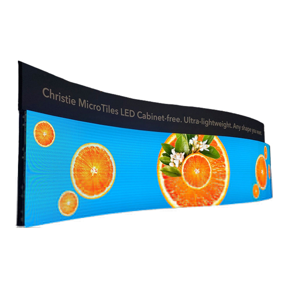
Product overview Christie MicroTiles LED tiles are modular, high-quality image display units that can be configured to create small display configurations as well as larger more complex display canvases of virtually any size and shape. Each tile captures a portion of the image and applies scaling, as required, which results in a single picture. -
Page 6: Important Safeguards
To prevent personal injury and to protect the device from damage, read and follow these safety precautions. General safety precautions Read all safety and warning guidelines before installing MicroTiles LED. Warning! If not avoided, the following could result in death or serious injury. •... -
Page 7: Remote Power Rack Shelf Safety Warnings
Learn about the labels that may be used on the product. Labels on your product may be yellow or black and white. General hazards Hazard warnings also apply to accessories once they are installed in a Christie product that is connected to power. Fire and Shock Hazard To prevent fire or shock hazards, do not expose this product to rain or moisture. - Page 8 Consult the service manual. Electrical labels Indicates the presence of an earth ground. MicroTiles LED Installation and Setup Guide 020-102825-04 Rev. 1 (07-2022) Copyright © 2022 Christie Digital Systems USA, Inc. All rights reserved. If printed, please recycle this document after use.
-
Page 9: Typical Microtiles Led Solution
Product overview Typical MicroTiles LED solution A typical MicroTiles LED installation contains a variety of components. LED tiles Octrollers—Each Octroller can control up to eight LED tiles. Remote Power Rack Shelf LED Wall Controller Video matrix switch and splicing video processor... -
Page 10: Cable And Component Layout And Design
The video source connections between the components are represented by the blue line. The power connections between the components are represented by the red line. MicroTiles LED Installation and Setup Guide 020-102825-04 Rev. 1 (07-2022) Copyright © 2022 Christie Digital Systems USA, Inc. All rights reserved. If printed, please recycle this document after use. -
Page 11: Wall Controller Interface And Ports
Reserved for future use. Sync in (SMA connector) Reserved for future use. MicroTiles LED Installation and Setup Guide 020-102825-04 Rev. 1 (07-2022) Copyright © 2022 Christie Digital Systems USA, Inc. All rights reserved. If printed, please recycle this document after use. -
Page 12: Octroller Ports
PWR OK—Connects to the local AC power supply when used in a redundant configuration. MicroTiles LED Installation and Setup Guide 020-102825-04 Rev. 1 (07-2022) Copyright © 2022 Christie Digital Systems USA, Inc. All rights reserved. If printed, please recycle this document after use. -
Page 13: Technical Support
Product overview Technical support Technical support for Christie Enterprise products is available at: • North and South America: +1-800-221-8025 or Support.Americas@christiedigital.com • Europe, Middle East, and Africa: +44 (0) 1189 778111 or Support.EMEA@christiedigital.com • Asia Pacific (support.apac@christiedigital.com): • Australia: +61 (0)7 3624 4888 or tech-Australia@christiedigital.com •... -
Page 14: Installation And Setup
External support for a display wall must be designed and implemented by a Christie qualified installer and must comply with local area regulations and safety standards. • The area behind the MicroTiles LED tiles is a restricted access location not accessible by the general public. •... -
Page 15: Installing The Mounting Sheets
Affix the mounting template in place on the wall with staples or low-adhesive two-sided tape. Christie recommends putting the staples or adhesive tape close to the anchor locations on the mounting template. This helps to keep the mounting template from lifting while drilling pilot holes. - Page 16 Affix the mounting template in place on the wall with staples or low-adhesive two-sided tape. MicroTiles LED Installation and Setup Guide 020-102825-04 Rev. 1 (07-2022) Copyright © 2022 Christie Digital Systems USA, Inc. All rights reserved. If printed, please recycle this document after use.
-
Page 17: Installing The Wall Anchors
To move the adjustment screw, remove the screw, and re-install it on the MicroTiles LED Installation and Setup Guide 020-102825-04 Rev. 1 (07-2022) Copyright © 2022 Christie Digital Systems USA, Inc. All rights reserved. If printed, please recycle this document after use. -
Page 18: Installing The Metal Mounting Sheets
(A) and the LED module tether holes are on the right side of the chassis cavity (B). MicroTiles LED Installation and Setup Guide 020-102825-04 Rev. 1 (07-2022) Copyright © 2022 Christie Digital Systems USA, Inc. All rights reserved. If printed, please recycle this document after use. -
Page 19: Adjusting The Wall To Be Flat
To make the distance consistent across the chassis plain, adjust the laser as needed. MicroTiles LED Installation and Setup Guide 020-102825-04 Rev. 1 (07-2022) Copyright © 2022 Christie Digital Systems USA, Inc. All rights reserved. If printed, please recycle this document after use. - Page 20 6. When the adjustment on the anchor is complete, securely finger tighten the anchor adjustment screw. MicroTiles LED Installation and Setup Guide 020-102825-04 Rev. 1 (07-2022) Copyright © 2022 Christie Digital Systems USA, Inc. All rights reserved. If printed, please recycle this document after use.
-
Page 21: Adjusting And Leveling The Mounting Sheets
8. On the other corner of the sheet, repeat steps 2 to 7. MicroTiles LED Installation and Setup Guide 020-102825-04 Rev. 1 (07-2022) Copyright © 2022 Christie Digital Systems USA, Inc. All rights reserved. If printed, please recycle this document after use. -
Page 22: Installing And Configuring The Remote Power Rack Shelf
However, each Octroller must be protected with a 20 to 30 A maximum circuit breaker with a medium trip delay. Alternate power systems must be reviewed and approved by Christie and by the local electrical authority at the installation site. -
Page 23: Resetting The Breakers
Installation and setup Christie accessories. Alternatively, create a custom cable using the Christie Main Power Cable Spool (P/N 154-122106-XX), Connector Kit (P/N 154-125109-XX), and Molex Crimping Tool (P/N 154-124108-XX). For more information on the Molex Crimping Tool, see the Molex documentation. -
Page 24: Mounting The Octroller
Various lengths of CAT 6 unshielded, UTP, 24 AWG pre-terminated cables are available from Christie. Alternatively, a custom length of Ethernet cable can be created using the Christie Cat 6 cable spool (P/N: 161-120104-XX), rJ45 Connect kit (P/N: 161-122106-XX) and Ethernet crimping tool (P/N: 11-121105-XX). -
Page 25: Installing The Chassis And Led Tiles
When the detection is successful, the web user interface displays the correct tile layout grid. 7. In the web user interface, to start the automatic tile mapping, select Auto Map. Christie recommends automatically mapping the tiles in the array after the chassis are installed, and after the LED tiles are installed on the chassis. -
Page 26: Removing Led Modules
3. For each LED module in the tile repeat steps 1 and 2. MicroTiles LED Installation and Setup Guide 020-102825-04 Rev. 1 (07-2022) Copyright © 2022 Christie Digital Systems USA, Inc. All rights reserved. If printed, please recycle this document after use. -
Page 27: Verifying The Hardware Installation
MicroTiles LED uses a dual-input configuration for displaying 3D content, where two video streams are provided by the video server, with the left eye supplied by one stream and the right eye supplied by the other. -
Page 28: 3D Requirements
3D shutter glasses. This synchronizes the active glasses to alternatively open and close for the active stereo 3D applications. MicroTiles LED Installation and Setup Guide 020-102825-04 Rev. 1 (07-2022) Copyright © 2022 Christie Digital Systems USA, Inc. All rights reserved. If printed, please recycle this document after use. -
Page 29: Cabling The Array
Various lengths of CAT 6 unshielded, UTP, 24 AWG pre-terminated cables are available from Christie. Alternatively, a custom length of Ethernet cable can be created using the Christie Cat 6 cable spool (P/N: 161-120104-XX), rJ45 Connect kit (P/N: 161-122106-XX) and Ethernet crimping tool (P/N: 11-121105-XX). -
Page 30: Disposing Of The Product Packaging
In the 3D Settings area select Enable 3D stereo in a single port. Disposing of the product packaging Once the product has been installed and set up, Christie recommends reusing or recycling the product packaging according to your local regulations. -
Page 31: Completing The Initial Configuration
MicroTiles LED tiles are equipped with neighbor detection, which automatically determines the location of each tile within the canvas and the overall configuration of the canvas. Christie recommends automatically mapping the tiles in the array after the chassis are installed, and after the LED tiles are installed on the chassis. -
Page 32: Adjusting The Brightness Levels Of The Seams Between Tiles
To select the seams in an area of the array, or to select the entire array, click and drag the mouse on a diagonal around the seams. MicroTiles LED Installation and Setup Guide 020-102825-04 Rev. 1 (07-2022) Copyright © 2022 Christie Digital Systems USA, Inc. All rights reserved. If printed, please recycle this document after use. - Page 33 4. To change the seam brightness, move the Seam Brightness slider or change the value in the brightness percentage field. MicroTiles LED Installation and Setup Guide 020-102825-04 Rev. 1 (07-2022) Copyright © 2022 Christie Digital Systems USA, Inc. All rights reserved. If printed, please recycle this document after use.
-
Page 34: Regulatory
• IEC 61000-3-3/EN61000-3-3: Limitations of Voltage Changes, Voltage Fluctuations, and Flicker MicroTiles LED Installation and Setup Guide 020-102825-04 Rev. 1 (07-2022) Copyright © 2022 Christie Digital Systems USA, Inc. All rights reserved. If printed, please recycle this document after use. -
Page 35: Immunity
Regulation (EC) No. 1907/2006 on the registration, evaluation, authorization and restriction of chemicals (REACH) and the applicable official amendment(s). MicroTiles LED Installation and Setup Guide 020-102825-04 Rev. 1 (07-2022) Copyright © 2022 Christie Digital Systems USA, Inc. All rights reserved. If printed, please recycle this document after use.
Need help?
Do you have a question about the MicroTiles LED and is the answer not in the manual?
Questions and answers