Table of Contents

Related Manuals for Bosch rexroth HQ 2/G-H


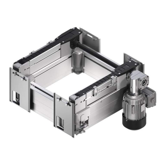
Summary of Contents for Bosch rexroth HQ 2/G-H
- Page 1 HQ 2/G-H, BS 2/G-250, HQ 2/C-H Lift transverse unit, belt section 3 842 996 370, HQ 2/G-H Assembly instructions Replaces: – 3 842 999 022, BS 2/G-250 ENGLISH 3 842 564 989/2022-06 3 842 999 002, HQ 2/C-H HQ 2/G-H HQ 2/C-H 564 988-00...
- Page 2 Our products are subject to natural wear and aging. © All rights reserved by Bosch Rexroth AG, also for the registration of industrial property rights. This document may not be reproduced or distributed to third parties without our consent.
-
Page 3: Table Of Contents
HQ 2/G-H with BS 2/G-250, HQ 2/C-H: Conversion to motor mounting M left (by customer) 7.6.2 Pre-assembling the mounting bracket 7.6.3 Installing the lift transverse unit 7.6.4 Pre-installing the DA 2/…-H damper kit 3 842 564 989/2022-06, MIT: HQ 2/G-H, BS 2/G-250, Bosch Rexroth AG... - Page 4 (MA) = M 10.7.2 HQ 2/G-H with BS 2/G-250, HQ 2/C-H: Tensioning the Conveyor chain 10.7.3 HQ 2/G-H, BS 2/G-250, replacing the duplex chain (roller chain) 10.7.4 Replacing flat top chain 10.7.5 Spare parts Bosch Rexroth AG, MIT: HQ 2/G-H, BS 2/G-250, 3 842 564 989/2022-06...
- Page 5 Function plans 17.1.1 Implementation in transverse section (TFE 1) 17.1.2 Implementation in longitudinal section (TFE 2) 17.1.3 Outfeeding from longitudinal conveyor (TFE 3) 17.1.4 Infeeding to longitudinal conveyor (TFE 4) 3 842 564 989/2022-06, MIT: HQ 2/G-H, BS 2/G-250, Bosch Rexroth AG...
-
Page 6: About This Documentation
"General notes on property and product damage", as well as before any sequence of actions or any required action which involves a risk of personal injury or property damage. Be sure to observe all safety precautions. Bosch Rexroth AG, MIT: HQ 2/G-H, BS 2/G-250, 3 842 564 989/2022-06... -
Page 7: Symbols
If this information is not observed, the product cannot be used and/or operated as designed. Single, independent action „ Numbered steps: The numbers indicate that the action steps are subsequent. 3 842 564 989/2022-06, MIT: HQ 2/G-H, BS 2/G-250, Bosch Rexroth AG... -
Page 8: Designations
• For ambient conditions, see page 75. The product is strictly intended for professional use and not for private use. The intended use also includes having read and understood these instructions, especially section 2 "Safety instructions". Bosch Rexroth AG, MIT: HQ 2/G-H, BS 2/G-250, 3 842 564 989/2022-06... -
Page 9: Improper Use
Any use other than that described in the section "Intended use" is considered improper and is not permitted. Bosch Rexroth AG is not liable for any damage resulting from improper use. The user alone bears any risks associated with improper use. The following foreseeable misuses also constitute improper use: •... -
Page 10: Product-Specific Safety Instructions
• Make sure that: – There are no obstacles preventing access to the EMERGENCY STOP controls. – All delivery points, workstations and passages are kept clear. Bosch Rexroth AG, MIT: HQ 2/G-H, BS 2/G-250, 3 842 564 989/2022-06... -
Page 11: Personal Protective Equipment
• Provide safety-related instructions to the operating personnel before initial commissioning or re-commissioning, and then at regular intervals. 3 842 564 989/2022-06, MIT: HQ 2/G-H, BS 2/G-250, Bosch Rexroth AG... -
Page 12: General Notes On Property And Product Damage
• 1 declaration of incorporation for BS 2/G-250, belt section 4.1 Condition on delivery • Lift transverse unit HQ 2/G-H / HQ 2/C-H ready for installation. • BS 2/G-250 belt section ready-to-install, the motor is enclosed separately. Bosch Rexroth AG, MIT: HQ 2/G-H, BS 2/G-250, 3 842 564 989/2022-06... -
Page 13: About This Product
• HQ 2/G-H and HQ 2/C-H: The accumulation operation is to be avoided, turn off the HQ 2/G-H and HQ 2/C-H as soon as the end position is reached. • Cable/plug or terminal box motor connection 3 842 564 989/2022-06, MIT: HQ 2/G-H, BS 2/G-250, Bosch Rexroth AG... -
Page 14: Specifications For Bs 2/G-250
• Depending on the version, motor mounting on the right-hand side (MA = R), left-hand side (MA = L) or in the center (MA = M). • Cable/plug or terminal box motor connection Bosch Rexroth AG, MIT: HQ 2/G-H, BS 2/G-250, 3 842 564 989/2022-06... -
Page 15: Product Description Hq 2/G-H And Hq 2/C-H
> 640 mm = 640 mm (4x) (2x) (2x) M8 x 20 M8 x 20 (4x) (4x) (8x) (4x) (8x) (8x) 564 988-03 Fig. 3: HQ (shown here: 480 x 640 mm, infeeding version) 3 842 564 989/2022-06, MIT: HQ 2/G-H, BS 2/G-250, Bosch Rexroth AG... - Page 16 ) Note the selection parameter wear pad. In conjunction with the duplex chain, the PE wear pad is required. In conjunction with the flat top chain, the PA wear pad is sufficient. ) With PE wear pad Bosch Rexroth AG, MIT: HQ 2/G-H, BS 2/G-250, 3 842 564 989/2022-06...
- Page 17 ) The customer must switch to motor mounting M on left (see section 7.6.1 "HQ 2/G-H with BS 2/G-250, HQ 2/C-H: Conversion to motor mounting M left (by customer)" on page 25). ‒ 3 842 564 989/2022-06, MIT: HQ 2/G-H, BS 2/G-250, Bosch Rexroth AG...
- Page 18 WTs). SW13 =25 Nm SW13 =25 Nm SW13 =25 Nm SW13 =25 Nm 564 988-12 Fig. 4: HQ, Possible installation of lateral guide (S) as a non-damped stop (B) Bosch Rexroth AG, MIT: HQ 2/G-H, BS 2/G-250, 3 842 564 989/2022-06...
- Page 19 BS .../ BS .../ BS .../ BS .../ ST ... ST ... ST ... ST ... Fig. 5: Main transport direction 3 842 564 989/2022-06, MIT: HQ 2/G-H, BS 2/G-250, Bosch Rexroth AG...
-
Page 20: Product Description For Bs 2/G-250
20/84 About this product 5.4 Product description for BS 2/G-250 Motor-gear combination, motor mounting: R, hanging Duplex chain (roller chain) b+25 b-75 554 988-17 Fig. 6: BS 2/G-250 belt section Bosch Rexroth AG, MIT: HQ 2/G-H, BS 2/G-250, 3 842 564 989/2022-06... -
Page 21: Identification Of The Product
• Protect the product from environmental influences, such as dirt and moisture. • Observe the ambient conditions, see page 75. • Support the product so that suspended motors/actuators/cylinders will not be strained. 3 842 564 989/2022-06, MIT: HQ 2/G-H, BS 2/G-250, Bosch Rexroth AG... -
Page 22: Assembly
During installation, be sure to maintain the ambient conditions specified in the „ Technical data (see page 75). 7.2.1 Installation position Install the product level and plumb, at right angles, and axially parallel. „ This ensures proper functioning and prevents premature wear. Bosch Rexroth AG, MIT: HQ 2/G-H, BS 2/G-250, 3 842 564 989/2022-06... -
Page 23: Fastening With T-Bolts
– 1x 3 842 146 815, foundation bracket – 1x 3 842 526 560, dowel – 2x 3 842 528 718, T-bolt – 2x 3 842 345 081, flange nut 3 842 564 989/2022-06, MIT: HQ 2/G-H, BS 2/G-250, Bosch Rexroth AG... -
Page 24: Symbols Used
Graphical depiction of the designation of components. The letters denote the components mentioned in the accompanying text. Detail view from a different direction, for example, the back or the bottom side of the product. Bosch Rexroth AG, MIT: HQ 2/G-H, BS 2/G-250, 3 842 564 989/2022-06... -
Page 25: Installing The Lift Transverse Unit
(for HQ 2/C-H) B2: Duplex chain (roller chain) (for HQ 2/G-H) Remove the covers from the drive heads. 564 988-20 Fig. 9: Conversion to motor mounting M left (by customer) (1/2) 3 842 564 989/2022-06, MIT: HQ 2/G-H, BS 2/G-250, Bosch Rexroth AG... - Page 26 =25 Nm on the drive heads (see Fig. 9). SW13 =25 Nm 564 988-21 Fig. 10: Conversion to motor mounting M left (by customer) (2/2) Alu = aluminum; Kst = plastic Bosch Rexroth AG, MIT: HQ 2/G-H, BS 2/G-250, 3 842 564 989/2022-06...
-
Page 27: Pre-Assembling The Mounting Bracket
Insert the T-bolts into the section profiles and gently pull on the flange nuts (mounting bracket can still be moved). 564 988-22 Fig. 11: HQ, pre-installation of the mounting bracket 3 842 564 989/2022-06, MIT: HQ 2/G-H, BS 2/G-250, Bosch Rexroth AG... -
Page 28: Installing The Lift Transverse Unit
Use a workpiece pallet to help align the product. SW13 =25 Nm =18 Nm 564 988-23 Fig. 12: Installation of the lift transverse unit (shown here using HQ 2/G-H, 480 x 640 mm as an example) Bosch Rexroth AG, MIT: HQ 2/G-H, BS 2/G-250, 3 842 564 989/2022-06... -
Page 29: Pre-Installing The Da 2
DA 2/250-H For more information, see the catalogue for the TS 2plus transfer system 564 988-24 Fig. 13: HQ, pre-installation of the damper kit DA 2/…-H (shown here using "infeeding" as an example) 3 842 564 989/2022-06, MIT: HQ 2/G-H, BS 2/G-250, Bosch Rexroth AG... -
Page 30: Installing The Damper Kit Da 2
Table 9: Dimensions for installation of the damper kit DA 2/…-H, infeeding Track width in the longitudinal conveyor Inatalling HQ 2/G-H or HQ 2/C-H in BS 2/… (mm) A (mm) B (mm) 1040 1200 1079 Bosch Rexroth AG, MIT: HQ 2/G-H, BS 2/G-250, 3 842 564 989/2022-06... -
Page 31: Installing The Damper Kit Da 2
Table 10: Dimensions for installation of the damper kit DA 2/…-H, outfeeding Track width in the longitudinal conveyor Inatalling HQ 2/G-H or HQ 2/C-H in BS 2/… (mm) A (mm) B (mm) 149.5 229.5 309.5 1040 429.5 1200 1079 509.5 3 842 564 989/2022-06, MIT: HQ 2/G-H, BS 2/G-250, Bosch Rexroth AG... -
Page 32: Hq 2/G-H / Hq 2/C-H, Mounting Da 2/100-C Damper, Infeed
SW13 =25 Nm HQ 2/G-H, HQ 2/C-H =8,7 Nm 564 988-27 Fig. 16: HQ 2/G-H / HQ 2/C-H, mounting DA 2/100-C damper, infeed Bosch Rexroth AG, MIT: HQ 2/G-H, BS 2/G-250, 3 842 564 989/2022-06... -
Page 33: Hq 2/G-H / Hq 2/C-H, Mounting Da 2/150-E Damper, Outfeed
Install the damper on „ the center of the lift transverse unit. SW13 =25 Nm HQ 2/G-H, HQ 2/C-H 564 988-28 Fig. 17: HQ 2/G-H / HQ 2/C-H, installation of damper DA 2/150-E, outfeeding 3 842 564 989/2022-06, MIT: HQ 2/G-H, BS 2/G-250, Bosch Rexroth AG... -
Page 34: Hq 2/G-H / Hq 2/C-H, Mounting Va 2/D-250 Slide Stop
Table 11: Dimensions for installation of the VA 2/D-250 slide stop Track width in the longitudinal conveyor Inatalling HQ 2/G-H or HQ 2/C-H in BS 2/… (mm) A (mm) B (mm) 1040 1200 1079 Bosch Rexroth AG, MIT: HQ 2/G-H, BS 2/G-250, 3 842 564 989/2022-06... -
Page 35: Hq, Mounting Lateral Guides
7.6.10 HQ, mounting lateral guides Table 12: Possible installation of lateral guide (S) as a non-damped stop (A) Motor mounting M (Standard) Motor mounting M left Any motor mounting ‒ 3 842 564 989/2022-06, MIT: HQ 2/G-H, BS 2/G-250, Bosch Rexroth AG... - Page 36 SW13 =25 Nm SW13 =25 Nm SW13 =25 Nm 564 988-12 Fig. 19: HQ 2/G-H, installation as a lateral guide (S) or as a non-damped stop (A) Bosch Rexroth AG, MIT: HQ 2/G-H, BS 2/G-250, 3 842 564 989/2022-06...
- Page 37 (A). B₁: Flat top chain (HQ 2/C-H) B₂: Duplex chain (roller chain) (HQ 2/G-H) > 640 mm 564 988-38 Fig. 20: HQ, position of the lateral guides 3 842 564 989/2022-06, MIT: HQ 2/G-H, BS 2/G-250, Bosch Rexroth AG...
-
Page 38: Hq 2/G-H, Hg 2/C-H, Mounting Position Monitoring Kit
= 2,5 Nm bracket down. All 3 lift positions can be detected/set/selected. +0,5 564 988-39 Fig. 21: HQ 2/G-H, HG 2/C-H, mounting position monitoring kit ) Customer selectable Bosch Rexroth AG, MIT: HQ 2/G-H, BS 2/G-250, 3 842 564 989/2022-06... -
Page 39: Hq, Pneumatic Connection Of The Product
• The pneumatic hoses on all 4 ports must be the same length! Connect the lift „ transverse unit to the compressed air supply. 564 988-40 Fig. 22: HQ, pneumatic connection 3 842 564 989/2022-06, MIT: HQ 2/G-H, BS 2/G-250, Bosch Rexroth AG... - Page 40 Lower to the bottom „ position. Then depressurize „ the valve (= middle switching position). Built-in springs lift the HQ... to the central position. 564 988-41 Fig. 23: HQ, pneumatic circuit diagram Bosch Rexroth AG, MIT: HQ 2/G-H, BS 2/G-250, 3 842 564 989/2022-06...
-
Page 41: Installing The Bs 2/G-250
BS 2/G-250 2 leg sets: 2000 mm. SZ 2 SZ 2/H SZ 2 SZ 2/H SW13 M = 25 Nm 564 988-42 Fig. 24: BS 2/G-250, installing the belt section on leg sets (1/2) 3 842 564 989/2022-06, MIT: HQ 2/G-H, BS 2/G-250, Bosch Rexroth AG... - Page 42 3 842 146 815 3 842 526 560 SW24 M = 25 Nm "A" SW13 M = 25 Nm 564 988-43 Fig. 25: BS 2/G-250, installing the belt section on leg sets (2/2) Bosch Rexroth AG, MIT: HQ 2/G-H, BS 2/G-250, 3 842 564 989/2022-06...
-
Page 43: Bs 2/G-250, Modify Mounting Position Of The Motor-Gear Combination
90° intervals. Install the screws (A). SW10 M =8,7 Nm 90° 90° 90° 90° 564 988-44 Fig. 26: BS 2/G-250, mounting position of the motor-gear combination 3 842 564 989/2022-06, MIT: HQ 2/G-H, BS 2/G-250, Bosch Rexroth AG... -
Page 44: Electrical Connection Of The Product
Please note: For motors that come with a fitted plug, correct the rotational direction in the control cabinet or at the socket contact (socket side). This makes replacement easier. Bosch Rexroth AG, MIT: HQ 2/G-H, BS 2/G-250, 3 842 564 989/2022-06... - Page 45 2U1 2V1 2W1 2U1 2V1 2W1 1U1 1V1 1W1 1U1 1V1 1W1 554 988-46 Fig. 28: Delta/wye wiring diagrams 554 988-47 Fig. 29: Optional motor connection with plug (AT = S) 3 842 564 989/2022-06, MIT: HQ 2/G-H, BS 2/G-250, Bosch Rexroth AG...
-
Page 46: Commissioning
• Only commission the product if all safety equipment has been installed in the system and is ready for use. • Only commission a product that has been completely installed. Bosch Rexroth AG, MIT: HQ 2/G-H, BS 2/G-250, 3 842 564 989/2022-06... -
Page 47: Residual Risks
Install appropriate guards. surface (above 65 °C) Let the unit cool down for at least 30 minutes before performing maintenance and/or repair work. T.R. 564 988-49 564 988-48 564 988-51 564 988-50 3 842 564 989/2022-06, MIT: HQ 2/G-H, BS 2/G-250, Bosch Rexroth AG... - Page 48 Install appropriate guards. Motor Touching of the hot Burning Let the unit cool down for at least 30 minutes surface (above 65 °C) before performing maintenance and/or repair work. 564 988-52 Bosch Rexroth AG, MIT: HQ 2/G-H, BS 2/G-250, 3 842 564 989/2022-06...
-
Page 49: Re-Commissioning After A Standstill
• Rotate in the "+" direction The movement is slower. • Rotate in the "–" direction The movement is faster. 564 988-53 Fig. 30: HQ 2/G-H, adjusting the lifting speed 3 842 564 989/2022-06, MIT: HQ 2/G-H, BS 2/G-250, Bosch Rexroth AG... -
Page 50: Operation
Workpiece pallets are both loaded and unloaded. Significantly different weights may require special measures to avoid malfunctions. This applies to: • The permitted congestion length before stop gates, • Damper functionality, • Dampened stop gates. Bosch Rexroth AG, MIT: HQ 2/G-H, BS 2/G-250, 3 842 564 989/2022-06... -
Page 51: Environmental Factors
In such instances, special care must be taken when planning the system, and the maintenance intervals must be correspondingly shortened. 3 842 564 989/2022-06, MIT: HQ 2/G-H, BS 2/G-250, Bosch Rexroth AG... -
Page 52: Maintenance And Repair
There is a risk of damage to property. Keep degreasers or aggressive cleaning agents away from the chain! „ Only clean the product with a damp cloth. „ Bosch Rexroth AG, MIT: HQ 2/G-H, BS 2/G-250, 3 842 564 989/2022-06... -
Page 53: Inspection
Risk of injury caused by sudden movements and falling objects. Only work on the conveyor chain when the belt section is stationary. „ Secure the system against being unintentionally switched on again. „ 3 842 564 989/2022-06, MIT: HQ 2/G-H, BS 2/G-250, Bosch Rexroth AG... -
Page 54: Conveyor Chain
Grease the conveyor chain with 1-2 g oil/m chain before the first start-up, then with 2-3 g oil/m chain every 1000 h. The flat top chain must also be lubricated laterally*). 564 988-55 Fig. 31: Lubricating points, flat top chain Bosch Rexroth AG, MIT: HQ 2/G-H, BS 2/G-250, 3 842 564 989/2022-06... -
Page 55: Bearings
• oil container, 3 842 562 941 • LU 2/P mounting kit, 3 842 562 923 • Adapter kit AS 2/R-300, -700 for HQ 2/C-H, 3 842 543 485 Adapter kit AS 2/C-100, -250 for HQ 2/G-H, 3 842 543 483 3 842 564 989/2022-06, MIT: HQ 2/G-H, BS 2/G-250, Bosch Rexroth AG... - Page 56 LU 2 You install the adapters LC 2 of the LU 2 automatic lubrication unit in the holes marked *). 558 998-56 Fig. 32: LU 2 automatic lubrication unit Bosch Rexroth AG, MIT: HQ 2/G-H, BS 2/G-250, 3 842 564 989/2022-06...
-
Page 57: Replacing Wear Parts
• For flat top chain – Chain lock, 3 842 535 333 – Disassembly tool, 8 981 010 510, for shortening/trimming the chain 3 842 551 234 8 981 010 510 564 988-57 Fig. 33: Accessories for replacing the chain 3 842 564 989/2022-06, MIT: HQ 2/G-H, BS 2/G-250, Bosch Rexroth AG... -
Page 58: Hq 2/G-H, Bs 2/G-250, Replacing The Motor
• If the motor is not in the proper position: Do NOT rotate the motor. Disconnect the motor from the gear and reconnect it. 564 988-58 Fig. 34: Replacing the motor (using HQ 2/G-H as an example) Bosch Rexroth AG, MIT: HQ 2/G-H, BS 2/G-250, 3 842 564 989/2022-06... -
Page 59: Hq 2/C-H, Hq 2/G-H And Bs 2/G-250, Replacing The Gear, Motor Mounting (Ma) = R/L (Outside)
, motor mounting (MA) = R/L (using HQ 2/G-H as an example) ) The exchange of the transmission can also be as in the chapter 7.6 on page 25 are carried out. 3 842 564 989/2022-06, MIT: HQ 2/G-H, BS 2/G-250, Bosch Rexroth AG... -
Page 60: Hq 2/G-H With Bs 2/G-250, Hq 2/C-H: Replacing The Gearbox, Motor Mounting (Ma) = M (Inside)
564 988-60 Fig. 36: Replacing the gear, motor mounting (MA) = M (using HQ 2/G-H as an example) Bosch Rexroth AG, MIT: HQ 2/G-H, BS 2/G-250, 3 842 564 989/2022-06... -
Page 61: Hq 2/G-H With Bs 2/G-250, Hq 2/C-H: Replacing The Gear, Motor Mounting (Ma) = M
• For belt sections with cross connectors, if possible do not open the cross connectors, but rather the gearbox as in chapter 7.6 on page 25 dismantle. Only open the cross connectors if necessary, otherwise the belt section will lose its alignment. 3 842 564 989/2022-06, MIT: HQ 2/G-H, BS 2/G-250, Bosch Rexroth AG... - Page 62 1 rotation. Loctite 242 =18 Nm 564 988-62 Fig. 38: Installing the belt section (using HQ 2/G-H as an example) Bosch Rexroth AG, MIT: HQ 2/G-H, BS 2/G-250, 3 842 564 989/2022-06...
-
Page 63: Hq 2/G-H With Bs 2/G-250, Hq 2/C-H: Tensioning The Conveyor Chain
The resulting elongation „ is compensated by spring force. Close the chain tensioners. =18 Nm 564 988-63 Fig. 39: Tensioning the conveyor chain (using HQ 2/G-H as an example) 3 842 564 989/2022-06, MIT: HQ 2/G-H, BS 2/G-250, Bosch Rexroth AG... -
Page 64: Hq 2/G-H, Bs 2/G-250, Replacing The Duplex Chain (Roller Chain)
(Only necessary if you want to replace the guides; to do this, remove the belt section from the lift unit: Remove the bottom covers of the drive heads.) Bosch Rexroth AG, MIT: HQ 2/G-H, BS 2/G-250, 3 842 564 989/2022-06... - Page 65 Re-tighten the chain tensioners. =2,5 Nm =5 Nm =18 Nm 564 988-65 Fig. 41: Slackening the duplex chain (using HQ 2/G-H as an example, shown without lift unit) 3 842 564 989/2022-06, MIT: HQ 2/G-H, BS 2/G-250, Bosch Rexroth AG...
- Page 66 Check the sprocket and „ the chain guides for break-in scoring. Replace worn parts. 564 988-66 Fig. 42: Removing the duplex chain (using HQ 2/G-H as an example, shown without lift unit) Bosch Rexroth AG, MIT: HQ 2/G-H, BS 2/G-250, 3 842 564 989/2022-06...
- Page 67 Install the cover sheets on the chain tensioners. =2,5 Nm T.R. =18 Nm 564 988-67 Fig. 43: Assembling and tensioning the duplex chain (using the HQ 2/G-H example) 3 842 564 989/2022-06, MIT: HQ 2/G-H, BS 2/G-250, Bosch Rexroth AG...
-
Page 68: Replacing Flat Top Chain
(0 842 904 229), using 1–2 g oil/m of chain, then every 1,000 hrs with 2–3 g oil/m of chain. *) Also lubricate the sides of the flat top chain. 564 988-71 Fig. 45: Lubricating points Bosch Rexroth AG, MIT: HQ 2/G-H, BS 2/G-250, 3 842 564 989/2022-06... - Page 69 Remove the belt section to the top. Remove the covers from the drive heads. Remove the cover sheets from the chain tensioners. 564988-72 Fig. 46: Preparing to replace the chain (flat top chain) 3 842 564 989/2022-06, MIT: HQ 2/G-H, BS 2/G-250, Bosch Rexroth AG...
- Page 70 Make sure the chain tensioner remains tensioned during assembly and „ cannot loosen unintentionally. Loosen the chain HQ 2/C-H tensioners. Slacken the chain as much as possible. Re-tighten the chain tensioners. 564988-73 Fig. 47: Slackening the flat top chain Bosch Rexroth AG, MIT: HQ 2/G-H, BS 2/G-250, 3 842 564 989/2022-06...
- Page 71 Pull the chain back from the drive heads. Remove the sliding piece. Pull the chain completely off of the belt section. 3 842 551 234 564988-74 Fig. 48: Removing the flat top chain 3 842 564 989/2022-06, MIT: HQ 2/G-H, BS 2/G-250, Bosch Rexroth AG...
- Page 72 Install the covers on the drive heads. Install the cover sheets on the chain tensioners. Install the belt section on the lift unit. 564988-75 Fig. 49: Installing and tensioning the chain Bosch Rexroth AG, MIT: HQ 2/G-H, BS 2/G-250, 3 842 564 989/2022-06...
-
Page 73: Spare Parts
• Protect the product from environmental influences, such as dirt and moisture. • Observe the ambient conditions, see page 75. • For products with motor installed: Support the product so that the motor is not placed under mechanical load. 3 842 564 989/2022-06, MIT: HQ 2/G-H, BS 2/G-250, Bosch Rexroth AG... -
Page 74: Disposal
14 Upgrading and modification • Do not modify the product. • The Bosch Rexroth warranty only applies to the configuration as delivered, and to approved upgrades. The manufacturer will not accept any warranty claims for systems with unapproved modifications or upgrades. -
Page 75: Technical Data
(Class 4 as per ISO 8573-1:2010) ) The pressure dew point should be at least 15 °C below the ambient temperature. • Oil content – Oil quantity ≤ 1 mg/m (Class 3 as per ISO 8573-1:2010) 3 842 564 989/2022-06, MIT: HQ 2/G-H, BS 2/G-250, Bosch Rexroth AG... -
Page 76: Appendix
Stop gate S … Signal transmitter Y … Valve Z … Cylinder Longitudinal conveyor (main section) Transverse conveyor (secondary section) Start pulse after end of start-up Enable cyclic travel Bosch Rexroth AG, MIT: HQ 2/G-H, BS 2/G-250, 3 842 564 989/2022-06... -
Page 77: Implementation In Transverse Section (Tfe 1)
= HQ up (Z2) = HQ down (Z2) = Extend DA damper (Z4), stop position Notes: • Approaching the central position, see page 40. • Distance Z1 - Z3 = l + 200 mm 3 842 564 989/2022-06, MIT: HQ 2/G-H, BS 2/G-250, Bosch Rexroth AG... -
Page 78: Implementation In Longitudinal Section (Tfe 2)
= Release secondary section, HQ free = Secondary section VE (Z1) = HQ up (Z2) = HQ down (Z2) = Extend DA damper (Z4) Notes: • Distance Z1 - Z3 = b + 200 mm Bosch Rexroth AG, MIT: HQ 2/G-H, BS 2/G-250, 3 842 564 989/2022-06... -
Page 79: Outfeeding From Longitudinal Conveyor (Tfe 3)
= Extend DA damper (Z4) = Straight-ahead signal Notes: • Approaching the central position, see page 40. • Distance Z1 - Z3 = l + 200 mm • Distance S2 - S3 = min. 200 mm 3 842 564 989/2022-06, MIT: HQ 2/G-H, BS 2/G-250, Bosch Rexroth AG... -
Page 80: Infeeding To Longitudinal Conveyor (Tfe 4)
WT before VE 2 WT after VE2 Secondary section VE/1 (Z1) 558 993-45 Main section VE/2 (Z2) HQ up (Z3) HQ down (Z3); not required Extend DA damper (Z4) P10 = Priority Bosch Rexroth AG, MIT: HQ 2/G-H, BS 2/G-250, 3 842 564 989/2022-06... - Page 81 81/84 3 842 564 989/2022-06, MIT: HQ 2/G-H, BS 2/G-250, Bosch Rexroth AG...
- Page 82 82/84 Bosch Rexroth AG, MIT: HQ 2/G-H, BS 2/G-250, 3 842 564 989/2022-06...
- Page 83 83/84 3 842 564 989/2022-06, MIT: HQ 2/G-H, BS 2/G-250, Bosch Rexroth AG...
- Page 84 Bosch Rexroth AG Postfach 30 02 07 70442 Stuttgart Germany Fax +49 711 811–7777 info@boschrexroth.de www.boschrexroth.com Subject to modifications 3 842 564 989/2022-06...
Need help?
Do you have a question about the rexroth HQ 2/G-H and is the answer not in the manual?
Questions and answers