Table of Contents
Advertisement
Available languages
Available languages
Quick Links
7876H-All_Manuals 3/19/14 11:48 AM Page 1
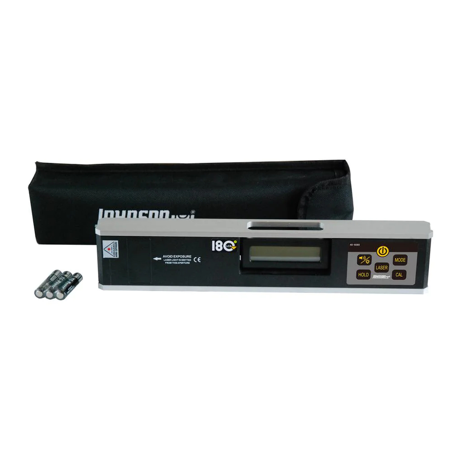
12" Magnetic Digital Laser Level
Model No. 40-6080
Instruction Manual
Congratulations on your choice of this Magnetic Digital Laser Level
with Rotating Display. We suggest you read this instruction manual
thoroughly before using the instrument. Save this instruction manual
for future use.
This is a Class IIIa laser tool and is manufactured to comply
with CFR 21, parts 1040.10 and 1040.11 as well as international
safety rule IEC 285.
©2014 Johnson Level & Tool - Rev. 3
1
Advertisement
Table of Contents

Related Manuals for Johnson 40-6080


Summary of Contents for Johnson 40-6080
- Page 1 Save this instruction manual for future use. This is a Class IIIa laser tool and is manufactured to comply with CFR 21, parts 1040.10 and 1040.11 as well as international safety rule IEC 285. ©2014 Johnson Level & Tool - Rev. 3...
- Page 2 • 0º and 90º-position of inclination is confirmed by a signal tone • Numbers invert for working overhead • Automatic Shut-off • Magnetic Base • 1/4" - 20 thread for connection to tripod ©2014 Johnson Level & Tool - Rev. 3...
- Page 3 Use of non-Johnson ® parts and accessories will void warranty. DANGER! Class IIIa Laser Product Max. Power Output: Wavelength: 640-660nm THIS TOOL EMITS LASER RADIATION. DO NOT STARE INTO BEAM. AVOID DIRECT EYE EXPOSURE. ©2014 Johnson Level & Tool - Rev. 3...
- Page 4 7876H-All_Manuals 3/19/14 11:48 AM Page 4 4. Location/Content of Warning Labels ©2014 Johnson Level & Tool - Rev. 3...
- Page 5 7876H-All_Manuals 3/19/14 11:48 AM Page 5 5. Location of Part/Components Laser Output Window LCD Display Keypad 1 1/4" Offset Battery Cover Battery Cover Screw ©2014 Johnson Level & Tool - Rev. 3...
- Page 6 Display After Installing the Batteries 1. After installing the new batteries the LCD will display “good”. 2. Then the LCD will display “-0-”. 3. Calibrate the instrument following the calibration procedure in Section 8. ©2014 Johnson Level & Tool - Rev. 3...
- Page 7 10º to 80º. A faster beep will start as you move closer to level or plumb. A steady tone will beep when level is at 0.0º or 90º. ©2014 Johnson Level & Tool - Rev. 3...
- Page 8 Mode Low Voltage Indication If the battery symbol on the display is low, change the batteries as soon as possible. Non-display of battery symbol means the battery is full. ©2014 Johnson Level & Tool - Rev. 3...
- Page 9 The laser output window will emit a bright red laser dot. Inclination Indication The triangle arrows displayed on the two ends of the LCD indicate the inclination direction of the laser digital level. ©2014 Johnson Level & Tool - Rev. 3...
- Page 10 7876H-All_Manuals 3/19/14 11:48 AM Page 10 When the laser digital level is at the position of 0 degree, the two arrows will show as follows: Rotating Display The LCD of the instrument can rotate 180 degrees. ©2014 Johnson Level & Tool - Rev. 3...
- Page 11 When the LCD shows -0-, it means the instrument has entered the calibration status. 2. Place the laser digital level on the horizontal reference surface, as shown in figure 5, after 10 seconds, press the CAL again, and the LCD shows -1-. ©2014 Johnson Level & Tool - Rev. 3...
- Page 12 3. Turn the laser digital level 180 degrees, as shown in figure 6, and after 10 seconds, press the CAL key again, and the LCD shows -2-. Wait for 2 seconds, and the laser digital level will show the angle reading. Calibration is now completed. ©2014 Johnson Level & Tool - Rev. 3...
- Page 13 Approx. battery life 70 hours continuous use Dimensions 12" x 2.36" x 1.25" (305 x 60 x 32mm) Weight 1.48 lbs (0.67 Kg) Working Temperature 14°F to 113°F (-10°C to +45°C) Center Screw Thread 1/4"-20 ©2014 Johnson Level & Tool - Rev. 3...
- Page 14 Keep the laser unit dry and clean, especially the laser output • window. Remove any moisture or dirt with a soft, dry cloth. Do not use harsh chemicals, strong detergents or cleaning • solvents to clean the laser unit. ©2014 Johnson Level & Tool - Rev. 3...
- Page 15 7876H-All_Manuals 3/19/14 11:48 AM Page 15 11. Product Warranty Johnson Level & Tool offers a three year limited warranty on each of its products. You can obtain a copy of the limited warranty for a Johnson Level & Tool product by contacting Johnson Level & Tool's Customer Service Department, as provided below, or by visiting our web site at www.johnsonlevel.com.
- Page 16 7876H-All_Manuals 3/19/14 11:48 AM Page 16 ©2014 Johnson Level & Tool - Rev. 3...
- Page 17 Ésta es una herramienta láser Clase IIIa y está fabricada según la norma CFR 21, partes 1040.10 y 1040.11, y la norma de seguridad internacional IEC 285. ©2014 Johnson Level & Tool - Rev. 3...
-
Page 18: Table Of Contents
• Indicador auditivo para nivel 0° y plomada 90° • Inversión digital automática para mediciones elevada • Apagado automático • Base magnética • Tornillo de 1/4" – 20 para conectarlo al trípode ©2014 Johnson Level & Tool - Rev. 3... -
Page 19: Información De Seguridad
• Utilice solamente partes y accesorios originales Johnson ® adquiridos en un concesionario autorizado por Johnson. El uso de partes y accesorios de otras marcas anulará la garantía. ¡PELIGRO! Producto Láser de Clase IIIa Salida Máxima de Corriente: 5mW... -
Page 20: Ubicación / Contenido De Las Etiquetas De Advertencia
EVITE LA EXPOSICIÓN DIRECTA A LOS OJOS. Producto Láser de Clase IIIa Salida Máxima de Corriente: 5mW Longitud de Onda: 640-660nm Este Producto cumple con los requerimientos aplicables de 21 CFR parts 1040.10 y 1040.11. ©2014 Johnson Level & Tool - Rev. 3... -
Page 21: Ubicación De Partes/Componentes
7876H-All_Manuals 3/19/14 11:48 AM Page 21 5. Ubicación de partes/componentes Ventana de salida Pantalla LCD Teclado del láser Compensación de 1-1/4" Cubierta de baterías Tornillo para la cubierta de baterías ©2014 Johnson Level & Tool - Rev. 3... -
Page 22: Instrucciones De Operación
1. Después de instalar baterías nuevas, la pantalla LCD mostrará “good” (“buenas”). 2. La pantalla mostrará después “-0-“. 3. Calibre el instrumento como se describe en la sección 8 – Auto-Chequeo y Calibración. ©2014 Johnson Level & Tool - Rev. 3... -
Page 23: Utilización Del Producto
10º y 80º, no habrá pitidos. El nivel emitirá un pitido más rápido entre más se acerque al nivel o plomada. El nivel emitirá un tono constante cuando el esté en 0º o 90º. ©2014 Johnson Level & Tool - Rev. 3... - Page 24 Si el símbolo de la batería en la pantalla indica bajo voltaje, cambie las baterías lo antes posible. Si este símbolo no aparece en la pantalla, quiere decir que la batería está cargada. ©2014 Johnson Level & Tool - Rev. 3...
- Page 25 Las flechas triangulares que aparecen en los dos extremos de la pantalla LCD indican la dirección de inclinación del nivel láser digital. Indicación de Inclinación Indicación de Inclinación Indicación de Inclinación Indicación de Inclinación Plano horizontal Plano horizontal ©2014 Johnson Level & Tool - Rev. 3...
- Page 26 7876H-All_Manuals 3/19/14 11:48 AM Page 26 Cuando el nivel láser digital está en posición 0º, las dos flechas indi- carán lo siguiente: Pantalla Rotativa La pantalla del instrumento puede rotar hasta 180 grados. ©2014 Johnson Level & Tool - Rev. 3...
-
Page 27: Auto-Chequeo Y Calibración
-0-, el modo de calibración ha sido activado. 2. Ubique el instrumento sobre una superficie de referencia, tal como se muestra en la figura 5. Después de 10 segundos vuelva a presionar el botón CAL. La pantalla mostrará -1-. ©2014 Johnson Level & Tool - Rev. 3... - Page 28 Después de 10 segundos, vuelva a presionar el botón CAL. La pantalla mostrará -2-. Después de 2 segundos más, el instrumento mostrará la lectura de ángulo. La calibración se ha completado. El mismo plano horizontal ©2014 Johnson Level & Tool - Rev. 3...
-
Page 29: Especificaciones Técnicas
La vida útil de la batería es de aproxi- madamente 70 horas de uso continuo Dimensiones 12" x 2.36" x 1.25" (350 x 60 x 32 mm) Peso 1.48 lbs. (0.67 Kg) Tornillo Central 1/4"-20 ©2014 Johnson Level & Tool - Rev. 3... -
Page 30: Cuidado Y Manejo
Mantenga la unidad del nivel seca y limpia. Elimine humedad o • suciedad con un paño seco y suave. No utilice químicos abrasivos, detergentes fuertes ni disolventes de • limpieza para limpiar el nivel. ©2014 Johnson Level & Tool - Rev. 3... -
Page 31: Garantía Del Producto
7876H-All_Manuals 3/19/14 11:48 AM Page 31 11. Garantía del Producto Johnson Level & Tool ofrece una garantía limitada de 3 años para cada uno de sus productos. Usted puede obtener una copia de la garantía limitada de un producto Johnson Level &... - Page 32 7876H-All_Manuals 3/19/14 11:48 AM Page 32 ©2014 Johnson Level & Tool - Rev. 3...
- Page 33 Cet outil laser de catégorie IIIa a été fabriqué en conformité avec le Code de règlements fédéraux des É.-U. (CFR 21), articles 1040 .10 et 1040 .11 et avec le règlement international sur la sécurité no IEC 285. ©2014 Johnson Level & Tool - Rev. 3...
- Page 34 • Inclinaisons de 0º et 90º confirmées par un signal sonore • Chiffres inversés pour mesures en hauteur • Arrêt automatique • Base magnétique • Filetage de 1/4 po - 20 permettant de raccorder l’instrument à un trépied ©2014 Johnson Level & Tool - Rev. 3...
- Page 35 • N’essayez pas de réparer ou de démonter l’outil laser. Si une personne non qualifiée tente de réparer cet outil, la garantie sera annulée. • N’utilisez que des pièces et accessoires Johnson ® d’origine achetés chez un détaillant autorisé...
- Page 36 LES YEUX. Produit à laser de classe IIIa Puissance de sortie maximale : 5 mW Longueurs d'onde : 640-660 nm Cet Outil Est Conforme Aux Exigences Applicables Du CFR21, Parties 1040.10 et 1040.11 ©2014 Johnson Level & Tool - Rev. 3...
- Page 37 5. Emplacement des pièces/des composants Fenêtre de sortie Affichage à CL Bloc numérique du laser Écart de 1 1/4 po Vis du couvercle Couvercle du compartiment des piles du compartiment des piles ©2014 Johnson Level & Tool - Rev. 3...
- Page 38 1. Après l'insertion de piles neuves, l'écran à CL affichera « good ». 2. L'écran à CL affichera ensuite « -0- ». 3. Calibrez l'instrument en suivant la procédure décrite à la Section 8. ©2014 Johnson Level & Tool - Rev. 3...
- Page 39 80°, il n'émet aucun bip. Lorsque vous vous rapprochez de la mise à niveau ou d'aplomb, l'instrument émet un bip plus rapide. Un bip continu retentit lorsque le niveau est à 0,0° ou 90. ©2014 Johnson Level & Tool - Rev. 3...
- Page 40 Lorsque l’intensité lumineuse du symbole de la pile affichée à l’écran est faible, l’utilisateur doit changer les piles rapidement. Lorsque la pile est neuve, le symbole de la pile ne s’affiche pas à l’écran. ©2014 Johnson Level & Tool - Rev. 3...
- Page 41 Les flèches triangulaires affichées aux deux extrémités de l’écran à CL indiquent le sens d’inclinaison du niveau numérique laser. Indication d’in- clinaison Indication d’incli- naison Indication d’in- clinaison Indication d’in- clinaison Plan horizontal Plan horizontal ©2014 Johnson Level & Tool - Rev. 3...
- Page 42 7876H-All_Manuals 3/19/14 11:48 AM Page 42 Lorsque le niveau numérique laser est à 0°, les deux flèches s’af- fichent de la manière suivante : Dispositif d’affichage rotatif Le dispositif d’affichage de l’instrument peut pivoter sur 180°. ©2014 Johnson Level & Tool - Rev. 3...
- Page 43 2. Posez le niveau laser numérique sur la surface de référence verticale tel que montré à la Figure 5. Attendez 10 secondes. Appuyez de nou- veau sur la touche «CAL» et l'écran affichera «-1-». ©2014 Johnson Level & Tool - Rev. 3...
- Page 44 Figure 6. Attendez encore 10 secondes. Appuyez de nouveau sur la touche «CAL» et l'écran affichera «-2-». Attendez 2 secondes et le niveau laser numérique affichera la lecture de l'angle. Le calibrage est maintenant terminé. Plan horizontal identique ©2014 Johnson Level & Tool - Rev. 3...
- Page 45 (350 x 60 x 32 mm) Poids 1,48 lb (0,67 kg) Plage de température d’utilisation -10° à +45 °C (14° à 113 °F ) Filetage de la vis centrale 1/4 po – 20 ©2014 Johnson Level & Tool - Rev. 3...
- Page 46 Veillez à ce que l’instrument soit toujours sec et propre. • Enlevez l’humidité ou la poussière à l’aide d’un chiffon doux et sec. N’utilisez pas de produits chimiques forts, de détergents • abrasifs ni de solvants pour nettoyer le niveau. ©2014 Johnson Level & Tool - Rev. 3...
- Page 47 ® . À défaut de quoi, la garantie limitée de Johnson Level & Tool (s’il y a lieu) sera nulle et AUCUNE GARANTIE ne pourra s’appliquer. Communiquez avec un de nos centres de service pour toute réparation qui n’est pas couverte par la garantie. Pour connaître la liste de nos centres de service, rendez-vous sur notre site Internet, le www.johnsonlevel.com, ou appelez...
- Page 48 7876H-All_Manuals 3/19/14 11:48 AM Page 48 ©2014 Johnson Level & Tool - Rev. 3...
Need help?
Do you have a question about the 40-6080 and is the answer not in the manual?
Questions and answers