Table of Contents
Advertisement
Quick Links
Download this manual
See also:
Instruction Manual
40-6065 Laser Digital Level
Service Manual
Content
1 Disassembly of instrument
1.1 Disassembly of keypad parts
1.2 Disassembly of horizontal-angle sensor parts
1.3 Disassembly of laser parts
4. Solutions for usual malfunctions
40-6065 digital level is a kind of high accurate instrument. If there are any malfunctions, the instrument must be
serviced by authorized dealers of JOHNSON, or back to our company for servicing. When you repair this instrument,
you should conform to this manual. Any unprofessional persons are not allowed to disassemble the instrument or
perform any internal servicing by themselves.
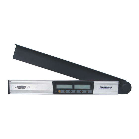
Figure 1: appearance of the instrument
1. Disassembly of instrument
1.1 Disassembly of keypad parts
(1) Loosen the lock knob (1-9#), and turn the angle square board (1-8#) by a certain angle.
(2) Screw off the 6pcs crosshead sunk bolts M2.5×8(1-6#), take off the keypad parts, and then pull out the terminal
pins of power, horizontal-angle sensor as well as include angle sensor.
(3) Tear out the membrane (1-3#), unclench the 3pcs bolt covers (1-7#), and disassemble the 6pcs crosshead plate
bolts M2.5×10(1-4#).
(4) Pull out the 6pcs connecting staffs (1-2#), then disconnect the keypad (1-1#) and main circuit board (1-5#).
Advertisement
Table of Contents

Subscribe to Our Youtube Channel
Related Manuals for Johnson 40-6065


Summary of Contents for Johnson 40-6065
-
Page 1: Table Of Contents
4. Solutions for usual malfunctions 40-6065 digital level is a kind of high accurate instrument. If there are any malfunctions, the instrument must be serviced by authorized dealers of JOHNSON, or back to our company for servicing. When you repair this instrument, you should conform to this manual. - Page 2 Figure 2 1-1 Keypad 1-4 Crosshead Plate Bolt M2.5×10 1-7 Bolt Cover 1-2 Connecting Staff 1-5 Main Circuit Board 1-8 Angle Square Board 1-3 Membrane 1-6 Crosshead Sunk Bolt M2.5×8 1-9 Lock Knob 2). Disassembly of horizontal-angle sensor parts (1) Turn the angle square board by a certain angle. (2) Disassemble the 3pcs crosshead sunk bolts M3×10(2-5#)and 2pcs crosshead sunk bolt M2.5×25(2-8#), pull out the horizontal-angle sensor parts, and take off the press plate (2-3#).
-
Page 3: Disassembly Of Ruler Body Parts
4-8 Electrical Brush Seat 4-12 Angle Square Board Parts Note: All the above is the general dissembling course of 40-6065, and the assembling course of 40-6065 is just the contrary. While repairing the instrument, it should take the disassembling level, procedure and method according to the practical situation. -
Page 4: Accuracy Check Of Horizontal Angle
2.1 Accuracy check of horizontal angle Reference platform setting As shown in figure 6, set a reference platform that has four flat and smooth sides and is 10m away from the wall. Side A is horizontal, and its horizontal angle is 0°±10", Side C is parallel with and below side A, with the horizontal angle is 0°±1°. -
Page 5: Accuracy Calibration Of Horizontal Angle
Figure 11 Figure 12 Figure 13 Figure 14 270 degree check (1) (1) As shown in figure 13, place the instrument against D plane and power on, notice the LCD display (left), wait 10 seconds till the displayed data stable and record the angle value. (2) As shown in figure 14, rotate the instrument by 180 degree in D plane, wait 10 seconds again till the displayed data stable then record the second angle value. -
Page 6: Accuracy Check And Calibration Of Laser Spot
2.3 Accuracy check and calibration of laser spot (1) Mark a reference point on the wall, and its horizontal accuracy should not be less than 5″. (2) Power on the instrument, and observe the distance from the laser spot to the reference point. If the vertical distance error from the laser spot to the reference point is out of ±3mm range, or the horizontal distance error from the laser spot to the reference point is out of ±20mm range, it means that it is necessary to recalibrate the accuracy of the laser spot. -
Page 7: Accuracy Calibration Of Included Angle
Check of other included angles Reference platform setting Baseboard Figure 22 As shown in figure 22, set a reference baseboard and several reference blocking boards, which should be flat and smooth enough. The included angle between two adjacent blocking boards is 10°. The included angle between the baseboard and the blocking board could reach a maximum of 170°... -
Page 8: Electric Connection Drawing
Figure 24 Calibration of 0° included angle In the state as shown in figure 21, if you find the angle is beyond tolerance, it is necessary to recalibrate the instrument. The detailed calibration procedures are the same as the step 2-6 described in the 180° included angle calibration. The only difference is that in the calibration of 0°included angle,, the reading displaying on the LCD should be set as “-0-”. - Page 9 4. Solutions for usual malfunctions Malfunction phenomenon Cause Repair method The battery is empty Replace with the new batteries The switch is loose contact Replace the switch Failure to power on The power line is cut off Weld the leading wire The connection line is loose.
Need help?
Do you have a question about the 40-6065 and is the answer not in the manual?
Questions and answers