
Related Manuals for Sony VPL-FHZ700


Summary of Contents for Sony VPL-FHZ700
- Page 1 4-544-271-13 (1) Data Projector Operating Instructions Before operating the unit, please read this manual and supplied Quick Reference Manual thoroughly and retain it for future reference. VPL-FHZ700L...
-
Page 2: Table Of Contents
Table of Contents The Information Menu .....35 Overview Location and Function of Controls ..3 Network Main Unit ........3 Using Network Features ....36 Terminals ........4 Displaying the Control Window of Remote Commander and Control the Projector with a Web Panel .......... -
Page 3: Location And Function Of Controls
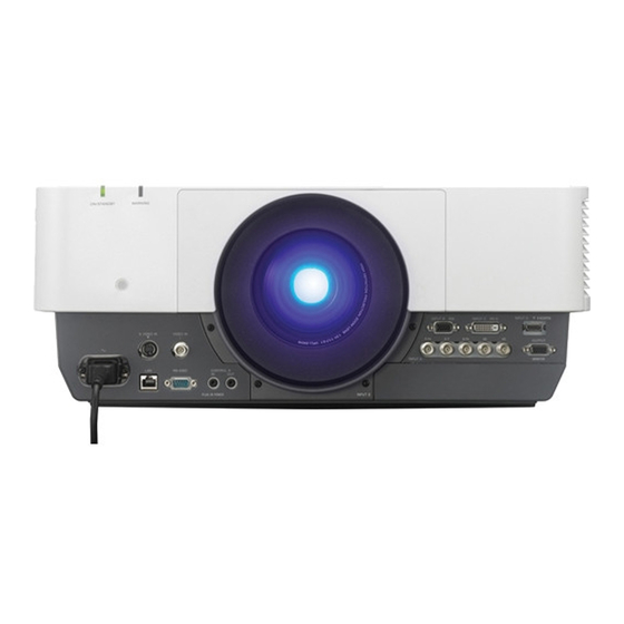
B Overview Location and Function of Controls Main Unit a Lens (not supplied) (page 47) l Rear feet (adjustable) (page 16) b Front panel m Antitheft lock Connects to an optional antitheft cable c Air filter cover (page 43) manufactured by Kensington. For details, visit the Kensington’s web d Ventilation holes (intake) site. -
Page 4: Terminals
(CONTROL S OUT) Note For coupling control of multiple * Regarding attachable optional adaptor, projectors with the wired Remote consult with qualified Sony personnel. Commander. Output (page 11) m AC IN (-) socket Connects the supplied AC power cord. h OUTPUT... -
Page 5: Remote Commander And Control Panel
Remote Commander and Control Panel Remote Commander b Selecting an input signal (page 14) INPUT key (main unit) Direct input select keys (Remote Commander) The F key is not provided in this projector. c Operating a menu (page 21) ENTER /V/v/B/b (arrow) keys MENU key RETURN key RESET key... - Page 6 2 Press the V/v/B/b keys to move the • Picture settings set for one picture may digital zoom icon to the point on the not be reflected as two pictures. image you wish to enlarge. BLANK key 3 Press the D ZOOM + key or the D Cuts off the image.
- Page 7 Dimming About Remote Commander operation Standby Mode: Low • Direct the Remote Commander toward the (go to step 6) remote control receiver. User: Sets each item of the energy- • The shorter the distance between the saving mode menu as you desire Remote Commander and the projector is, (go to step 3).
-
Page 8: Connecting The Projector
B Preparation Connecting the Projector Notes • Turn off all equipment before making any connections. • Use the proper cables for each connection. • Insert the cable plugs firmly; Loose connections may reduce performance of picture signals or cause a malfunction. When pulling out a cable, be sure to grip it by the plug, not the cable itself. •... -
Page 9: Connecting Video Equipment
INPUT C For connecting a computer with a DVI-D output terminal. DVI-D output terminal INPUT C DVI-D DVI-D cable (not supplied) Computer INPUT D For connecting a computer with an HDMI output terminal. HDMI output terminal HDMI cable (not supplied) Computer Notes •... - Page 10 VIDEO IN For connecting video equipment with a video output terminal. Video – BNC cable Video output (not supplied) terminal Video equipment INPUT A For connection when there is a long distance between the video equipment and projector. output terminal Component –...
-
Page 11: Connecting An External Monitor
To fix the HDMI cable Fix the cable to the cable tie holder at the bottom of the projector, using a commercially available cable tie, as in the illustration. Use a cable tie of less than 1.9 mm × 3.8 mm in thickness. Bottom of the projector Cable tie (commercially available) - Page 12 • Use a straight LAN cable (commercially-available) with a shield of CAT5e or CAT6 to connect the main unit and HDBaseT equipment. Connecting to the computer INPUT E HDBaseT transmitter HDMI output terminal HDMI cable (not supplied) Computer Connecting to video equipment INPUT E HDBaseT transmitter HDMI output...
- Page 13 Connecting to network equipment terminal LAN cable (straight type) (not supplied) Computer Wired connection Tablet PC/Smartphone Hub, Wireless router Computer Wireless connection HDBaseT transmitter Note When using network features, be sure to check if “LAN Setting” is set to “via HDBaseT” (page 29). Connecting the Projector...
-
Page 14: Projecting/Adjusting An Image
B Projecting/Adjusting an Image Projecting an Image The size of a projected image depends on the distance between the projector and screen. Install the projector so that the projected image fits the screen size. For details on projection distances “Projection Distance and Lens Shift Range” (page 53) and projected image sizes, see Input select window Computer... -
Page 15: Adjusting The Focus, Size, And Position Of The Projected Image
Adjusting the Focus, Size, and Position of the Projected image Focus Size (Zoom) Position (Lens shift) When attaching the Electric When attaching the Electric Press the LENS SHIFT/SHIFT focus lens zoom lens key on the projector or the Press the FOCUS key on the Press the ZOOM key on the Remote Commander then press projector or the Remote... - Page 16 If the projected image is Adjusting the tilt of the projector trapezoidally-distorted in the vertical with the rear feet (adjustable) plane When the projector is installed on an uneven surface, you can adjust using the rear feet Press the KEYSTONE key on the (adjustable).
- Page 17 Selecting the corner(s) of the image to be corrected Move x using V/v/B/b to select the corner you want to correct. Increase the setting Press the ENTER key. The cursor appears. Decrease setting Press the RESET key to restore the projected image before adjustment.
- Page 18 Adjust using this cursor Adjust using this cursor You can adjust the deflection of the You can adjust the deflection of the side, using V/v/B/b. side, using V/v/B/b. You can adjust the center point of You can adjust the center point of deflection using V/v.
-
Page 19: Turning Off The Power
Note that more detailed adjustment for Edge Blending is possible using a PC application. Assign the blending width. For more details, consult with qualified Sony personnel. Set the blending width according to the • When multiple projectors are set up in a line, overlapping range for the source signal. - Page 20 ECO gauge This gauge indicates the current effectiveness of the projector’s ECO function. (For details on the ECO function, see “ECO MODE key” (page 6) and “ECO” (page 29).) The leaf icons are displayed when the projector is shut down. The number of displayed icons varies according to how much energy is saved as a result of using the ECO function.
-
Page 21: Using A Menu
B Adjustments and Settings Using a Menu To return to the selection screen of the Using a MENU setting items, press the B key or the RETURN key. Also, to reset the setting value of an item to its factory preset Note value, press the RESET key during setting or adjusting. -
Page 22: The Picture Menu
The Picture Menu For adjusting the picture for each input signal. Setting items Description Picture Mode Dynamic: Emphasizes the contrast to produce a “dynamic” picture. Standard: Makes the picture be natural and well balanced. Presentation: Makes the picture bright to suit for a presentation. Reset The picture settings are initialized to their factory preset values. - Page 23 *5: When a progressive signal is input, this option is not available. *6: Available when a computer signal is input from the DVI-D input terminal (INPUT C), HDMI input terminal (INPUT D), or optional adaptor (INPUT E). This projector is not to be used as a device for medical diagnosis.
-
Page 24: The Screen Menu
The Screen Menu For adjusting the size, position, and aspect ratio of the projected image for each input signal. Setting items Description Aspect Changes the aspect ratio of the projected image (page 26). When the Full1: Displays the image to fit the maximum projected image size without computer changing the aspect ratio of the input signal. - Page 25 *3: Available when “Aspect” is “Zoom” and “Screen Aspect” is 16:10 or 16:9. *4: Available when a computer signal is input from the RGB input terminal (INPUT A, INPUT B). *5: If the projected image includes a large amount of black portion around it, the APA function will not work properly and a part of the image may not be displayed on the screen.
- Page 26 Aspect *1: If you select “Normal,” the image is Input signal Recommended projected in the same resolution as the setting value and input signal without changing the aspect projected image ratio of the original image. *1 *2 (4:3) (Full1) *2: If you select “Full2,” the image is projected to fit the projected image size, regardless *1 *2 (16:9)
-
Page 27: The Function Menu
The Function Menu The Function menu is used for setting various functions of the projector. Setting items Description Smart APA On/Off: When set to “On,” executes APA automatically when a signal is input. CC Display CC1/CC2/CC3/CC4/Text1/Text2/Text3/Text4: Select the closed caption service (Captions or Text). -
Page 28: The Operation Menu
“Off” after adjusting the lens. Note *1: You will not be able to use the projector if you forget your password. If you call qualified Sony personnel because you have forgotten the password, you will be asked to verify the projector’s serial number and your identity. -
Page 29: The Connection/Power Menu
The Connection/Power Menu The Connection/Power menu is used for setting for the connections and power. Setting items Description Network Setting IPv4 Setting IP Address Setup Auto (DHCP): The IP address is assigned automatically from the DHCP server such as a router. Manual: To specify the IP Address manually. - Page 30 Setting items Description Auto Power Saving With No Input Light Cutoff: The light turns off automatically and power consumption is reduced if no signal is input for about two minutes. The light turns on again when a signal is input or any key is pressed. In Light Cutoff, the ON/STANDBY indicator lights in orange.
- Page 31 *10:When “Standby Mode” is set to “Low,” the network and network control function cannot be operated while the projector is in standby mode. The Connection/Power Menu...
-
Page 32: The Installation Menu
The Installation Menu The Installation menu is used for installing the projector. Setting items Description Edge Blending On/Off: When set to “On,” the Edge Blending function is enabled. Set to “Off” when you do not project using multiple projectors. Blending Sets the edge blending width. - Page 33 Setting items Description Installation Attitude Link to Image Flip/Right Side Up/Upside Down/Front Down/Front Up/ Portrait 1/Portrait 2: Change the cooling setting to suit to the installation attitude. When set to “Link to Image Flip,” the cooling setting changes based on the setting of “Image Flip.” Continuing to use the wrong setting may affect component reliability.
- Page 34 Setting items Description Color Matching Adjust/Reset: For correcting the brightness and color of the whole projected image manually from the signal level in six steps. Notes *1: You cannot adjust anything other than the targeted adjustment zones in “Zone Black Level Adj.” *2: When selecting the correction zone of “Zone Black Level Adj.,”...
-
Page 35: The Information Menu
The Information Menu The Information menu enables you to confirm various information on the projector, such as the total usage hours of a light. Items Description Model Name Displays the model name. Serial No. Displays the serial number. fH / fV (horizontal Displays the horizontal frequency/vertical frequency/signal type of the frequency/vertical current input signal. -
Page 36: Using Network Features
B Network LAN cable Using Network (straight type) (not supplied) Features terminal Connection to the network allows you to operate the following features: • Checking the current status of the projector via a Web browser. • Remotely controlling the projector via a Web browser. -
Page 37: Confirming The Information Regarding The Projector
16 characters for each. keys on the supplied Remote Commander. Note Using the e-mail report If you forget your password, consult with Function qualified Sony personnel. Set the e-mail report function on the Setup page. Using Network Features... - Page 38 Entered values will not be applied unless Enter the outgoing e-mail address in you click on [Apply]. the Email Address box then check the Report Timing check box of the e-mail Click on [Owner information] to enter report to be sent. the owner information recorded in the mail report.
-
Page 39: Indicators
Flashes in red The projector is in abnormal status. Symptoms are indicated by number of flashes. Address the problem in accordance with the following. If the symptom is shown again, consult with qualified Sony personnel. Flashes twice The internal temperature is unusually high. Check the items below. -
Page 40: Messages List
Constant Brightness Although “Constant Brightness” is selected, the brightness that cannot be maintained. is set cannot be maintained due to the lifetime of the light source. Consult with qualified Sony personnel. Messages List... -
Page 41: Troubleshooting
Troubleshooting Before asking to have the projector repaired, try to diagnose the problem, following the instructions below. Symptom Remedy Page The power is not turned Check if the AC power cord is firmly connected. – When the “Panel Key Lock” is set to “On,” you cannot turn on the projector using the ?/1 key on the projector. - Page 42 Mode” affect brightness of the image. Check if the value is appropriate. The image will be dark when the light source is burnt out. Check “Light Timer,” and consult with qualified Sony personnel. “With Static Signal” is set to “On.”...
-
Page 43: Cleaning The Air Filter
Front with a new one. For details on a new air filter, consult with Air filter cover qualified Sony personnel. Caution Lock button If you continue to use the projector even after the message is displayed, dust may accumulate, clogging it. - Page 44 Remove the four air filter cartridges Tabs (right) Tabs (left) (two in each air filter unit) from the air filter units and clean the air filter with a vacuum cleaner. When attaching the air filter cartridge to the cartridge holder, push the air filter cartridge in fully until the tabs of the cartridge holder click (4 points each air filter cartridge, a total of 8 points).
-
Page 45: Installing The Optional Adaptor
Tighten the two screws on the optional Installing the adaptor. Optional Adaptor You can install the optional adaptor in INPUT E of the terminals section of the projector. Notes • Turn off the projector and disconnect the AC power cord from a wall outlet before installing the optional adaptor. -
Page 46: Specifications
Specifications Item Description Model name VPL-FHZ700L Display system 3 LCD system Display device Size of effective 0.95" (24.1 mm) × 3, Aspect ratio 16:10 display area Number of pixels 6,912,000 (1920 × 1200 × 3) pixels Light source Laser diode Light output 7,000 lm (when “Light Output Mode”... - Page 47 Item Description Model name VPL-FHZ700L Control signal RS-232C terminal: D-Sub 9 pin male input/output LAN terminal: RJ45, 10BASE-T/100BASE-TX CONTROL S input terminal (DC power supply): Stereo mini jack, 5 Vp-p, Plug in power DC 5 V CONTROL S output terminal: Stereo mini jack Operating 0 °C to 40 °C (32 °F to 104 °F)/35% to 85% (no temperature/...
- Page 48 Item Description Model name VPL-FHZ700L *5 *6 Projection Lens VPLL-FM22 : Manual focus, Projected image size: 40" to 300" (1.02 m to 7.62 m), Maximum external dimensions (W × H × D): 88 × 88 × 169 mm (3 " × 3 "...
- Page 49 *2: For details, refer to “Acceptable Input Signals” on page 51. *3: Not all optional accessories are available in all countries and area. Please check with your local Sony Authorized Dealer. *4: Information on accessories in this manual is current as of February 2015.
- Page 50 RGB input terminal (Mini D-sub 15- Pin assignment pin, female) DVI-D terminal (DVI-D, female) Video input Power supply T.M.D.S. +5 V Power (red) R input for DDC Data2– Video input T.M.D.S. Ground (return (green) G Data2+ for +5 V) Video input T.M.D.S.
- Page 51 HDMI terminal (HDMI, female) Input terminal fH [kHz]/ INPUT C/ Resolution INPUT A/ fV [Hz] INPUT D/ INPUT B INPUT E 800 × 600 35.2/56 – T.M.D.S. T.M.D.S. 37.9/60 Data2+ Clock Shield 48.1/72 – T.M.D.S. T.M.D.S. Data2 Shield Clock– 46.9/75 –...
- Page 52 Video signal Combinations of Input Signals Input terminal Main picture Sub picture INPUT C/ Signal fV [Hz] VIDEO/ INPUT A INPUT A INPUT D/ INPUT B (RGB) S VIDEO (RGB/YP INPUT E INPUT B (RGB) – NTSC – – INPUT C (DVI-D) PAL/ –...
-
Page 53: Projection Distance And Lens Shift Range
Projection Distance and Lens Shift Range The projection distance refers to the distance between the front of the lens and the projected surface. Projection distance L Front of the lens Projected image The lens shift range represents the distance in percent (%) by which the lens can be shifted from the center of the projected image. - Page 54 Projection distance Unit: m (inches) Projection image size Projection distance L Diagonal Width × Height VPLL-FM22 VPLL-ZM42 VPLL-ZM102 80" (2.03 m) 1.72 × 1.08 1.48 3.17 – 3.98 5.62 – 8.33 (68 × 42) (58) (125 – 157) (221 – 328) 100"...
- Page 55 Lens Projection distance L (minimal length) Projection distance L (maximal length) VPLL-ZM42 L = 0.0403 × D – 0.0558 L = 0.0504 × D – 0.0524 (L = 1.5861 × D – 2.1962) (L = 1.9861 × D – 2.0625) VPLL-ZM102 L = 0.0724 ×...
- Page 56 x VPLL-Z4007 = VS = 15 – 2.500 × (HS or HS ) [%] – – = HS = 6 – 0.400 × (VS or VS ) [%] – – x VPLL-4008 × = VS = 41 – 2.158 or HS ) [%] –...
-
Page 57: Dimensions
Dimensions Front Unit: mm (inches) 530 (20 INPUT B INPUT C DVI-D INPUT D HDMI S VIDEO IN VIDEO IN OUTPUT MONITOR INPUT A RS-232C CONTROL S PLUG IN POWER INPUT E 265 (10 Center of the lens Bottom Unit: mm (inches) 545 (21 474 (18 137.2... - Page 58 When using the PSS-630 projector suspension support Unit: mm (inches) 350 (13 380 (15) 410 (16 455 (18) 440 (17 485 (19 470 (18 515 (20 500 (19 545 (21 575 (22 605 (23 Center of the lens Front of the cabinet Center of the lens 150 (5...
- Page 59 Location information of the labels Warning label Explanatory label Light source specifications Lens Zoom Zoom 4.0 W laser diodes × 48 maximum: α minimum: α Wavelength: 440 - 450 nm VPLL-FM22 68° – Beam divergence angle from lens of VPLL-ZM42 36°...
- Page 60 The distance L’ between the front of About Trademarks the lens (center) and the front of the • Adobe Acrobat is a trademark of Adobe cabinet Systems Incorporated. Unit: mm (inches) • Kensington is a registered trademark of Lens L’ Type Kensington Technology Group.
-
Page 61: Index
Index ECO ............29 ECO MODE (Energy-saving mode) ..6 Edge Blending ........32 E-mail report ........... 37 AC IN socket ..........4 Expert Setting ......... 22 Acceptable input signal ......51 Adjust Signal ...........24 Air filter cover ...........3 fH ............35 All Reset ..........27 Film Mode .......... - Page 62 Light Timer ..........35 Security Lock ...........28 Location and function of controls ..... 3 Selecting an input signal ......5 Serial No..........35 Sharpness ..........22 Shift ...........15, 24 Main unit ........... 3 Smart APA ..........27 Menu Position ......... 28 Specifications ...........46 Messages list ...........
- Page 63 Sony Corporation...