Table of Contents
Advertisement
Quick Links
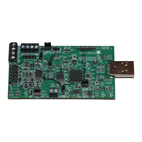
This user's guide describes the characteristics, operation, and use of the ADS1x20EVM. These evaluation
modules are an evaluation system for the ADS1220, a 24-bit, low-power, multichannel, delta-sigma (ΔΣ),
analog-to-digital converter (ADC) and the ADS1120, which is the 16-bit version of the ADS1220. The EVM
allows evaluation of all aspects of the ADS1x20 devices.
This document includes an EVM Quick Start, hardware and software details, bill of materials, and
schematic.
Table 1
www.ti.com.
Device
ADS1120
ADS1220
SN74LVC2G157
TPS76333
MSP430, ADCPro are trademarks of Texas Instruments.
SPI is a trademark of Motorola.
2
I
C is a trademark of NXP Semiconductors.
Omega is a registered trademark of Omega Engineering Limited.
Samtec is a trademark of Samtec, Inc.
Vishay is a registered trademark of Vishay Intertechnology, Inc.
All other trademarks are the property of their respective owners.
SBAU203 – July 2013
Submit Documentation Feedback
ADS1x20EVM
lists the related documents available through the Texas Instruments web site at
Table 1. EVM-Compatible Device Data Sheets
Literature Number
SBAS535
SBAS501
SCES207
SLVS181
Copyright © 2013, Texas Instruments Incorporated
Device
Literature Number
MSP430F5528
SLAS590
TPS3838L30
SLVS292
SN74LVC125A
SCAS290
—
User's Guide
SBAU203 – July 2013
ADS1x20EVM
—
ADS1x20EVM
1
Advertisement
Table of Contents

Related Manuals for Texas Instruments ADS1x20EVM


Summary of Contents for Texas Instruments ADS1x20EVM
-
Page 1: Evm-Compatible Device Data Sheets
ADS1x20EVM ADS1x20EVM This user's guide describes the characteristics, operation, and use of the ADS1x20EVM. These evaluation modules are an evaluation system for the ADS1220, a 24-bit, low-power, multichannel, delta-sigma (ΔΣ), analog-to-digital converter (ADC) and the ADS1120, which is the 16-bit version of the ADS1220. The EVM allows evaluation of all aspects of the ADS1x20 devices. -
Page 2: Table Of Contents
J2: RTD Terminal Block Connector ....................J5: Auxiliary Connector ..................... JTAG Interface Connections ..................JAC: External Interface Connector ..................JDB: External Interface Connector ..................ADS1x20EVM Bill of Materials ADS1x20EVM SBAU203 – July 2013 Submit Documentation Feedback Copyright © 2013, Texas Instruments Incorporated... -
Page 3: Evm Overview
MSP430 microcontroller with JTAG interface • Compatible with the TI LaunchPad The ADS1x20EVM includes an interface for serial communication that can be used with ADCPro™ to quickly evaluate the device. This manual covers the operation of the ADS1x20EVM. Throughout this document, the abbreviation EVM and the term evaluation module are synonymous with the ADS1120EVM and ADS1220EVM. -
Page 4: Quick Start
Default Jumper and Switch Configuration Figure 1 shows the jumpers found on the EVM and the respective factory default conditions for each. Figure 1. ADS1x20EVM Default Jumper Locations Table 2 lists the primary jumpers and the factory default conditions. Table 2. Default Jumper and Switch Configuration... -
Page 5: Quick Reference
REF0 dedicated reference input connected to J2.4 and J4.9-10, and • REF1 shared with analog inputs connected to J1.1, J1.4, J2.2, J4.2, J4.8, J6.1, and J6.4. SBAU203 – July 2013 ADS1x20EVM Submit Documentation Feedback Copyright © 2013, Texas Instruments Incorporated... -
Page 6: Using The Ads1220Evm Adcpro Plug-In
ADS1220 is in single conversion mode in a power-down state. No data can be collected while not in Cont Conv and are only useful for monitoring supply currents to determine power consumption of the ADS1220 while in power-down. ADS1x20EVM SBAU203 – July 2013 Submit Documentation Feedback Copyright © 2013, Texas Instruments Incorporated... -
Page 7: O Config
The Burnout Current Sources button controls the 10-µA burnout current sources. When this button is lit green, the burnout current is routed through the selected MUX channel and detects any breaks or shorts to a connected sensor. SBAU203 – July 2013 ADS1x20EVM Submit Documentation Feedback Copyright © 2013, Texas Instruments Incorporated... -
Page 8: Current And Ref
ADS1220. When using an external reference, change the VREF indicator to the appropriate reference voltage value. This adjustment ensures that the results displayed in the test plug-in of ADCPro are changed to the correct value. ADS1x20EVM SBAU203 – July 2013 Submit Documentation Feedback Copyright © 2013, Texas Instruments Incorporated... - Page 9 The About tab provides information on the EVM hardware and software versions. Plug-in Version is the software version of the ADCPro plug-in. Firmware Version is the firmware version loaded and running on the processor. SBAU203 – July 2013 ADS1x20EVM Submit Documentation Feedback Copyright © 2013, Texas Instruments Incorporated...
-
Page 10: Ads1220Evm Hardware Details
By default, the series input resistors are populated with 0-Ω resistors and the capacitors are not installed. No circuitry is provided to buffer these signals before connecting to the converter. ADS1x20EVM SBAU203 – July 2013 Submit Documentation Feedback Copyright © 2013, Texas Instruments Incorporated... -
Page 11: J4: Primary Analog Interface Pinout
EXC– can be connected to AGND through JP2, or through the low-side switch of AIN3/REFN1 of the ADS1220. Pin 1 is at the top right-hand corner, located next to the reference designator. EXC+ can be connected to AVDD through JP1. SBAU203 – July 2013 ADS1x20EVM Submit Documentation Feedback Copyright © 2013, Texas Instruments Incorporated... -
Page 12: J2: Rtd Terminal Block Connector
EVM. Device pads are available to create filter combinations for both differential and common-mode filters for many different input configurations. Filtering combinations are also included for filtering the external reference inputs. ADS1x20EVM SBAU203 – July 2013 Submit Documentation Feedback Copyright © 2013, Texas Instruments Incorporated... -
Page 13: J5: Auxiliary Connector
Section 5.4.2 for details on these pins. The second method is by using the bootstrap loader (BSL) of the MSP430. For further information, see the Texas Instruments web site at www.ti.com. Alternative control of the ADS1220 from other processors is possible by either connecting the processor control signals to the test points for the digital signals, or by using the JAC and JDB connectors located on the bottom-side of the ADS1220EVM. -
Page 14: Jtag Interface Connections
Pin 13 Pin 14 Pin 11 Pin 7 TDI/VPP Pin 3 TDO/TDI Pin 1 TEST/VPP Pin 8 Pin 5 VCC debugger Pin 2 VCC target Pin 4 ADS1x20EVM SBAU203 – July 2013 Submit Documentation Feedback Copyright © 2013, Texas Instruments Incorporated... -
Page 15: Jac: External Interface Connector
JAC, both the +3.3 V and +5 V can be connected as either a source or target supply. If +3.3 V is supplied to the EVM, jumper JP8 should be removed so that U5 does not sink current from an external source. SBAU203 – July 2013 ADS1x20EVM Submit Documentation Feedback Copyright © 2013, Texas Instruments Incorporated... -
Page 16: Schematic And Bill Of Materials
Hazardous Substances (RoHS) Directive. Some part numbers may be either leaded or RoHS. Verify that purchased components are RoHS-compliant. (For more information about TI's position on RoHS compliance, see www.ti.com.) Table 12. ADS1x20EVM Bill of Materials Item No. Value Ref Des... - Page 17 Schematic and Bill of Materials www.ti.com Table 12. ADS1x20EVM Bill of Materials (continued) Item No. Value Ref Des Description Manufacturer Part Number IC, Single 2 Line To 1 Line Data SN74LVC2G157DCT Selector/Multiplexer IC, 256K CMOS Serial EEPROM Microchip 24AA256-I/ST IC, +3.3V LDO Regulator, 150mA...
- Page 18 Assembly Variant: Variant name not interpreted Sheet: warrant that this design will meet the specifications, will be suitable for your application or fit for any particular purpose, or will operate in an implementation. Texas Instruments and/or its Drawn By: File: ADS1x20EVM-PW.SchDoc...
- Page 19 Any exceptions to this are strictly prohibited and unauthorized by Texas Instruments unless user has obtained appropriate experimental/development licenses from local regulatory authorities, which is responsibility of user including its acceptable authorization.
- Page 20 FCC Interference Statement for Class B EVM devices This equipment has been tested and found to comply with the limits for a Class B digital device, pursuant to part 15 of the FCC Rules. These limits are designed to provide reasonable protection against harmful interference in a residential installation. This equipment generates, uses and can radiate radio frequency energy and, if not installed and used in accordance with the instructions, may cause harmful interference to radio communications.
- Page 21 Also, please do not transfer this product, unless you give the same notice above to the transferee. Please note that if you could not follow the instructions above, you will be subject to penalties of Radio Law of Japan. Texas Instruments Japan Limited (address) 24-1, Nishi-Shinjuku 6 chome, Shinjuku-ku, Tokyo, Japan http://www.tij.co.jp...
- Page 22 FDA Class III or similar classification, then you must specifically notify TI of such intent and enter into a separate Assurance and Indemnity Agreement. Mailing Address: Texas Instruments, Post Office Box 655303, Dallas, Texas 75265 Copyright © 2013, Texas Instruments Incorporated...
- Page 23 IMPORTANT NOTICE Texas Instruments Incorporated and its subsidiaries (TI) reserve the right to make corrections, enhancements, improvements and other changes to its semiconductor products and services per JESD46, latest issue, and to discontinue any product or service per JESD48, latest issue.
- Page 24 Mouser Electronics Authorized Distributor Click to View Pricing, Inventory, Delivery & Lifecycle Information: Texas Instruments ADS1120EVM...
Need help?
Do you have a question about the ADS1x20EVM and is the answer not in the manual?
Questions and answers