Table of Contents
Advertisement
Quick Links
Advertisement
Table of Contents

Related Manuals for Kobold ADI-1F Series


Summary of Contents for Kobold ADI-1F Series
- Page 1 Operating Instruction Operating Instruction Universal Indicating Unit Frequency input: 0.01 Hz bis 99.99 kHz Connection for NAMUR-, NPN-, PNP- and TTL-sensors ect o se so s Model: ADI-1F... 96x96 mm ADI-1F.pdf Stand: K04/0522 96x96...
- Page 2 Identification Options – break-down ordering code: A D I- 1 F 0 0 0 2 0 0 Standard type ADI Bargraph and Digital display, red Bargraph 55 points 270°, digital display 5-digit, 14 mm Type of display Frequency input 0.01 Hz – 99.99 kHz Power supply 100-240 VAC +/- 10% (50-60Hz) / DC 10-40 VDC / 18-30 VAC 50/60 Hz...
-
Page 3: Table Of Contents
Contents Brief description Assembly Electrical connection Electrical connection Description of function and operation Setting up the device 5.1. Switching on 5.2. Standard parameterisation (flat operation level) Value assignment for the triggering of the signal input of the digital display and bargraph display 5 3 P 5.3. - Page 4 (info.de@kobold.com) in PDF format, specifying the relevant invoice number and serial number. If you wish, the operating instructions can also be sent to you by post in paper form against an applicable postage fee.
-
Page 5: Brief Description
1. Brief description 1. Brief description The panel meter instrument ADI-1F is a 5-digit digital display with a 55 points bargraph display and two galvanic insulated setpoints; designed for pulse signals respectively 2- and 3-wire sensors The configuration happens via four keys at the front The integrated programming sensors. -
Page 6: Assembly
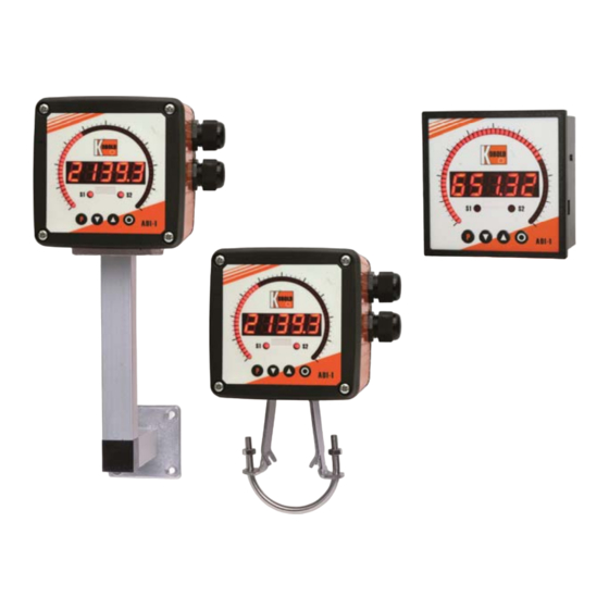
2. Assembly 2. Assembly Please read the Safety advice on page 37 before installation and keep this user manual for future reference. After removing the fixing elements, insert the device. Check the seal to make sure it fits securely. Click the fixing elements back into place and tighten the clamping screws by hand. Then use a screwdriver to tighten them another half a turn. - Page 7 2. Montage 2.2 Mounting field housing For the assembling of ADI-1 field housing please use the M4 screws. Optionally the housing can be delivered with wall mounting or pipe mounting For the electrically connection please pull the be delivered with wall mounting or pipe mounting. For the electrically connection please pull the housing lead back.
-
Page 8: Electrical Connection
3. Electrical connection 3. Electrical connection Model ADI-1V000200 with supply of 100-240 VAC Model ADI-1V300200 with supply of 10-40 VDC Attention! For devices with sensor supply, terminal clamps 4 and 18, aswell as 3 and 19 are connected galvanically in the device. - Page 9 3. Electrical connection ADI-1F with a frequency input / pulse input...
-
Page 10: Description Of Function And Operation
4. Description of function and operation 4. Description of function and operation Operation The operation is divided into three different levels. Menu level (delivery status) This level is for the standard settings of the device. Only menu items which are sufficent to set the device into operation are displayed. - Page 11 4. Description of functions and operation Funktion chart:...
-
Page 12: Setting Up The Device
5. Setting up the device 5. Setting up the device 5.1. Switching-on Once the installation is complete, you can start the device by applying the voltage supply. Before, Once the installation is complete, you can start the device by applying the voltage supply. Before, check once again that all electrical connections are correct. - Page 13 5. Setting up the device Menu level Parameterisation level Setting the start/offset value of the measuring range offs: Setting the start/offset value of the measuring range, offs: Default: 0 Enter the start/offset value from the smallest to the highest digit [▲] [▼] and confirm each digit with [P].
- Page 14 5. Setting up the device Menu level Parameterisation level Setting of the impulse delay dELAY Setting of the impulse delay, dELAY: Default: 0 With the impulse delay of 0 – 250 s (max), frequencies can be collected, which are even smaller than by the predetermined measuring time of the device.
- Page 15 5. Setting up the device Menü-Ebene Parameter-Ebene Selection of analog output Out rA: Selection of analog output, Out.rA: Default: 4‐20 Three output signals are available: 0-10 VDC, 0-20 mA and 4-20 mA, with this function, the demanded signal is selected. Setting up the final value of the analog output, Out.En: Default: 10000 The final value is adjusted from the smallest digit to the highest digit with [▲] [▼] and digit by...
- Page 16 5. Setting up the device Menu level Parameterisation level Function if display falls below / exceeds limit value FU 1 Function if display falls below / exceeds limit value, FU‐1: Default: high The limit value undercut can be selected with Louu (LOW = lower limit value) and limit value exceedance can be selected with high (HIGH = upper limit value).
-
Page 17: Programming Interlock „Run" I I T L K
5. Setting up the device Menu level Parameterisation level Master code (4-digit number-combination free available) A CodE: Master code (4-digit number-combination free available), A.CodE: Default: 1234 With this code, all parameters can be unlocked, if LOC has been activated before under menu item run. -
Page 18: Extended Parameterisation (Professional Operation Level)
5. Setting up the device 5.4. Extended parameterisation (Professional operation level) 5.4.1. Signal input parameters 5.4.1. Signal input parameters Menu group level Menu level Menu level Parameterisation level Selection of the input signal, tYPE: Default: fre9u If the scaling of the device is done via SEnS.F (Sensor calibration), the frequency range needs to be preset under rAnGE and is adjusted by application of the final value /initial value. - Page 19 5. Setting up the device Menu level Parameterisation level Setting the start/offset value of the measuring range ff : Setting the start/offset value of the measuring range, offs: Default: 0 Enter the start/offset value from the smallest to the highest digit [▲] [▼] and confirm each digit with [P] After the last digit the display switches back to the menu level If Sens F was selected as with [P].
- Page 20 5. Setting up the device Menu level Parameterisation level Setting of the impulse delay dELAY: Setting of the impulse delay, dELAY: Default: 0 With the impulse delay of 0 – 250 s (max), frequencies can be collected, which are even smaller than by the predetermined measuring time of the device.
- Page 21 5. Setting up the device Menu level Parameterisation level Display values for setpoints dIS Display values for setpoints, dIS.01 … dIS.30: Under this parameter setpoints are defined according to their value. At the sensor calibration, like at Endwert/Offset, one is asked at the end if a calibration shall be activated. Analog values for setpoints, InP.01 …...
-
Page 22: General Device Parameters „Fct
5. Setting up the device 5.4.2. General device parameters Menu group level Menu level Menu level Parameterisation level Display time, DISEC: Default: 01.0 then The display is set up with [▲] [▼]. Thereby you jump until 1 second in 0.1 steps and until 10.0 seconds in 1.0-steps. - Page 23 5. Setting up the device Menu level Parameterisation level Dynamic for the sliding average determination t Dynamic for the sliding average determination, step: Default: no With step the sliding average determination can be adjusted dynamically. If 6pro or 12pro is selected, a frequency value with a variance of 6% or 12% of the current display value is taken over directly for the sliding averaging.
- Page 24 5. Setting up the device Menu level Parameterisation level Display dISPL Display, dISPL: Default: Actua With this function the current measuring value, min-/max value, totaliser value, the process- controlled Hold-value, the sliding average value, the constant value or the difference between the constant value and the current value can be allocated to the display.
- Page 25 5. Setting up the device Menu level Parameterisation level Assignment (deposit) of key functions tASt: Assignment (deposit) of key functions, tASt: Default: no For the operation mode, special functions can be deposited on the navigation keys [▲] [▼], in particular this function is made for devices in housing size 48x24 which do not have a 4th key ([O] key).
- Page 26 5. Setting up the device Menu level Parameterisation level Special function [O]-key tASt 4: Special function [O]-key, tASt.4: Default: no … For the operation mode, special functions can be deposited on the [O]-Taste. This function is activated by pressing the key. With tArA the device is set temporarily on a parameterised value. The device acknowledges the correct taring with oo0oo in the display.
-
Page 27: Bargraph Functions „Bar
5. Setting up the device 5.4.3. Bargraph functions Menu group level Menu level Menu level Parameterisation level Bargraph, Ba.src: Default: actua With this function the following values can be allocated to the display: the current measurand, the min/max value, the totaliser value, the process-controlled hold value, the sliding average value, the constant value or the difference between constant and current value of the bargraph. - Page 28 5. Setting up the device Menu level Parameterisation level Bargraph alerting ba l1m: Bargraph alerting, ba.l1m: Default: no During a breach of the alarms (AL1 to Al4), a flashing of the dots can be allocated to the bargraph by selecting Flash If No is adjusted the bargrag remains statical With [P] the selection is by selecting Flash.
- Page 29 5. Setting up the device 5.4.4. Safety parameters Menu group level Menu level Menu level Parameterisation level Setting up the user code, U.Code: Default: 0000 Via this code reduced sets of parameters out le and al lev can be unlocked in case of a locked Via this code, reduced sets of parameters out.le and al.lev can be unlocked, in case of a locked programming.
-
Page 30: Analog Output Parameters „Out
5. Setting up the device Menu level Parameterisation level Back to menu group level rEt: Back to menu group level, rEt: With [P] the selection is confirmed and the device changes into menu group level „– COD –“. 5 4 5 Analog output parameters 5.4.5. - Page 31 5. Setting up the device Menu level Parameterisation level Setting the final value of the analog output, Out.En: Default: 10000 The final value is adjusted from the smallest to the highest digit with [▲] [▼] and confirmed digit per digit with [P]. A minus sign can only be parameterised on the highest digit. After the last digit the device changes back into menu level.
-
Page 32: Relay Functions „Rel
5. Setting up the device 5.4.6. Relay functions Menu group level Menu group level Menu level Menu level Menu level Parameterisation level Parameterisation level Alarmierung Relais 1, rEL‐1: Default: al‐1 …. …. Each setpoint (optional) can be linked up via 4 alarms (by default). This can either be inserted at activated alarms Al‐1/4 or de-activated alarms Aln1/4. - Page 33 5. Setting up the device Menu level Parameterisation level Alarms for relay 1 CoM 1: Alarms for relay 1, CoM‐1: Default: a.1 …. The allocation of the alarms to relay 1 happens via this parameter, one alarm or a group of alarms can be chosen.
-
Page 34: Alarm Parameters „Al1
5. Setting up the device Menu level Parameterisation level Alarms for relay 2 CoM 2: Alarms for relay 2, CoM‐2: Default: a.2 …. The allocation of the alarms to relay 1 happens via this parameter, one alarm or a group of alarms can be chosen. - Page 35 5. Setting up the device Menu level Parameterisation level Threshold values / Limit values LI 1: Threshold values / Limit values, LI‐1: Default: 2000 The limit value defines the threshold, that activates/deactivates an alarm. Hysteresis for threshold values, HY‐1: Default: 00000 The delayed reaction of the alarm is the difference to the threshold value, which is defined by the hysteresis.
-
Page 36: Totaliser (Volume Metering) „Tot
5. Setting up the device 5.4.8. Totaliser (Volume metering) Menu group level Menu group level Menu level Menu level Parameterisation level Totaliser state, total: Default: off The totaliser makes measurements on a time base of e g l/h possible at this the scaled input The totaliser makes measurements on a time base of e.g. -
Page 37: Reset To Factory Settings
6. Reset to default values Menu level Parameterisation level Totaliser reset tot re: Totaliser reset, tot.re: Default: 000 The reset value is adjusted from the smallest to the highest digit with the navigation keys [▲] [▼] and digit per digit confirmed with [P]. After the last digit, the display switches back to the menu level. -
Page 38: Alarms / Relay
7. Alarms / Relays 7. Alarms / Relays This device has 4 virtual alarms that can monitor one limit value in regard of an undercut or exceedance. Each alarm can be allocated to an optional relay output S1-S2; furthermore alarms can be controlled by events like e g hold value or min /max value can be controlled by events like e.g. -
Page 39: Programmer Examples
9. Programmer examples 8. Programmer examples Examples: Adjustment according to number of sprockets at unknown rotation speed. - nearly 100% of the rotation speeds are in the range of 0 to 30 000 r p m - nearly 100% of the rotation speeds are in the range of 0 to 30.000 r.p.m. - the number of sprockets varies (without gearing) between 1 and 100 - in automation, the frequency supply never exceeds 10 kHz (rather 3 kHz) Assume a rotation speed of 60 r.p.m. - Page 40 9. Programmer examples Example: Rotation speed of a machine shaft There are 4 sprockets on one machine shaft. Applied in an angle of 90° to each other and to the rotation speed measurement. The sprockets are collected via a proximity switch and evaluated by the frequency device, which shall display the rotation speed in U/min.
-
Page 41: Technical Data
10. Technical data 9. Technical data Panel meter housing Dimensions Dimensions Field housing: 117x117x127mm (BxHxD) Field housing: 117x117x127mm (BxHxD) Installation housing: 96x96x82 mm (BxHxD) incl. plug-in terminal Panel cut-out 91.0 x 91.0 +0.6 +0.6 Wall thickness up to 10 mm Fixing Screw elements Material... - Page 42 10. Technical data Output Sensor supply Sensor supply 24 VDC / 50 mA; 12 VDC / 50 mA; 5 VDC / 20 mA 24 VDC / 50 mA; 12 VDC / 50 mA; 5 VDC / 20 mA Analog output 0/4-20 mA / burden 350 Ω...
-
Page 43: Safety Advices
11. Safety standard 10. Safety standard Please read the following safety advice and the assembly chapter 1 before installation and keep it for future reference. Proper use The ADI-1F-device is designed for the evaluation and display of sensor signals. Danger! Careless use or improper operation can result in personal injury and/or damage to the equipment. -
Page 44: Error Elimination
12. Error elimination 11. Error elimination Measures Error description • The input frequency is too high for the selected frequency range Correct range“ The input frequency is too high for the selected frequency range. Correct „range The device shows a The device shows a permanent overflow according to this. -
Page 45: Eu Declaration Of Conformance
12. Declaration of Conformance 12. EU Declaration of Conformance We, KOBOLD Messring GmbH, Hofheim-Ts, Germany, declare under our sole responsibility that the product: Universal Indicating Unit Model: ADI-1F... to which this declaration relates is in conformity with the standards noted below:...
Need help?
Do you have a question about the ADI-1F Series and is the answer not in the manual?
Questions and answers