Table of Contents
Advertisement
Advertisement
Table of Contents

Subscribe to Our Youtube Channel
Related Manuals for Kobold DRS 0 Series


Summary of Contents for Kobold DRS 0 Series
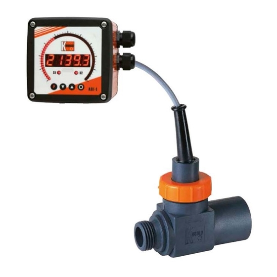
- Page 1 Operating Instruction Turbine-wheel Flow Meter Model: DRS...
-
Page 2: Table Of Contents
11. Order Codes ....................14 12. Dimensions ....................16 13. Disposal ...................... 17 14. EU Declaration of Conformance ..............18 15. UK Declaration of Conformity ..............19 Manufactured and sold by: Kobold Messring GmbH Nordring 22-24 D-65719 Hofheim Tel.: +49(0)6192-2990 Fax: +49(0)6192-23398 E-Mail: info.de@kobold.com... -
Page 3: Note
The instruction manuals on our website www.kobold.com are always for currently manufactured version of our products. Due to technical changes, the instruction manuals available online may not always correspond to the product version you have purchased. -
Page 4: Regulation Use
4. Regulation Use The DRS is to be installed only in the specified applications. Any use of the DRS sensor which exceeds the manufacturer’s specifications may invalidate the warranty and any resulting damage is not the responsibility of the manufacturer. The user assumes all risk for such usage. -
Page 5: Mechanical Connection
6. Mechanical Connection 6.1. Operational conditions check-up: • Flow volume • max. operational pressure • max. operational temperature Attention! Exceeding prescribed ranges may cause damage to ball- bearings and considerable measurement errors may result. 6.2. Mounting • Installation can take place in horizontal and ascending pipes, flow direction from bottom to top. -
Page 6: Electrical Connection
7. Electrical Connection 7.1. General Attention! Ensure that the power ratings of your supply system are in agreement with the power ratings of the flow meter. • Please ensure that the electric supply lines are not active. • Wire the connection cable/plug with the supply line according to the following connection diagram. -
Page 7: Evaluation Electronics: Frequency Output And Analogue Output With Pt100 (Drs
7.3. Evaluation electronics: Frequency output and analogue output with Pt100 (DRS-..P) Plug connection (..F300P; Cable connection (..F500P; ..F320P, ..F340P, ..F390P, ..F520P, ..F540P, F590P) ..L303P; ..L343P) brown: +Vs PT100 blue: GND black: Signal PT100 white: PT100 2-wire grey: PT100 2-wire 7.4. Evaluation electronics: analogue output (..L..) 3-conductor (..L303, ..L343) n.c. - Page 8 2-conductor (..L342) n.c. n.c. 2-conductor, DIN-plug (DRS-...L442) n.c. page 8 DRS K05/1116...
-
Page 9: Cable Outlet With M12X1 Angle Plug Electronic Options F3X And L3X
7.5. Cable outlet with M12x1 angle plug electronic options F3x and L3x When using a pre-assembled M12x1 connection cable with angled plug, the cable outlet is always aligned opposite to the flow direction. 7.6. Compact electronics: (..C30R, ..C30M, ..C34P, ..C34N) Please see Operating Instruction Manual for compact electronics with frequency output DRS K15/0722... -
Page 10: Commissioning
8. Commissioning 8.1. Frequency output The measuring units are pre-adjusted and ready for operation after electrical connection. 8.2. Analogue output The measuring units are pre-adjusted and ready for operation after electrical connection. 8.3. Compact electronics Please see Operating Instruction Manual for compact electronics with frequency output page 10 DRS K05/1116... -
Page 11: Maintenance
9. Maintenance As long as the medium to be measured is not polluted, the measuring unit is maintenance-free. In order to avoid problems, we recommend installation of a filter, such as magnet filter, Model MFR. Should cleaning be deemed necessary, the sensor must be uninstalled and rinsed thoroughly in clean water. -
Page 12: Technical Information
10. Technical information 10.1. Sensor data Measuring range: 2-40 L/min water Sensor pulse output: 384 Hz at 40 L/min Metal Sensor (DRS-...150; DRS-...250) 352 Hz at 40 L/min plastic sensor (DRS-...350) Max. operating pressure: 200 bar (DRS-...150; DRS-...250) 16 bar (DRS- ...350) Temperature: -20 to +80 °C (medium, standard), -20...+150 °C (medium, -S00x), -20 to +100 °C (storage) - Page 13 DRS-...F390 Supply: 24 V ± 20 % Power consumption: 15 mA Pulse output: PNP, open collector, max. 20 mA Frequency divider: 1...1/128, factory setting Option: Pt 100, 2-wire Response time (Pt100): = 25 s (DRS-91…/-92…) = 100 s (DRS-93…) DRS-...L... Supply: 24 V ±...
-
Page 14: Order Codes
11. Order Codes Order Details (example: DRS-9350 I4 L303 0) Material Model Connection Evaluating electronics Option sensor housing Frequency output F300 = Plug connector M12x1, PNP F320 = Plug connector M12x1, PNP, divider 1:2 F340 = Plug connector M12x1, PNP, divider 1:4 F390 = Plug connector M12x1, PNP, divider 1... - Page 15 Order details OEM version example: DRS-0350 I4 K0000) Material Model Connection Evaluating electronics sensor housing Frequency output I4 = G 1/2 female thread Brass DRS-0150 K0000 = 1.5 m PUR cable, black, NPN, OEM without CE G4 = G 1/2 female/male thread S0000 = 1.5 m silicone cable, NPN, OEM without CE Stainless steel DRS-0250...
-
Page 16: Dimensions
12. Dimensions Connection threads: female/female; male/male and female/male with the same outer dimensions. Cable Kabel- version version M12x1 SW 32 DRS-...F/...L ∅ 44,5 13,5 Cable 2 m with plug M 12x1 SW 36 OBOLD SW 32 DRS-...C D = Sealing areas page 16 DRS K05/1116... -
Page 17: Disposal
13. Disposal Note! • Avoid environmental damage caused by media-contaminated parts • Dispose of the device and packaging in an environmentally friendly manner • Comply with applicable national and international disposal regulations and environmental regulations. Batteries Batteries containing pollutants are marked with a sign consisting of a crossed-out garbage can and the chemical symbol (Cd, Hg, Li or Pb) of the heavy metal that is decisive for the classification as containing pollutants: 1. -
Page 18: Eu Declaration Of Conformance
14. EU Declaration of Conformance We, KOBOLD-Messring GmbH, Hofheim-Ts, Germany, declare under our sole responsibility that the product: Turbine-wheel Flow Meter Model: DRS-… to which this declaration relates is in conformity with the standards noted below: EN 61000-6-4:2011 Electromagnetic compatibility (EMC) - Part 6-4: Generic standards - Emission... -
Page 19: Declaration Of Conformity
15. UK Declaration of Conformity We, KOBOLD Messring GmbH, Hofheim-Ts, Germany, declare under our sole responsibility that the product: Turbine-wheel Flow Meter model: DRS-... to which this declaration relates is in conformity with the standards noted below: BS EN 61000-6-4:2007+A1:2011 Electromagnetic compatibility (EMC).
Need help?
Do you have a question about the DRS 0 Series and is the answer not in the manual?
Questions and answers