
Related Manuals for Espressif Systems ESP32-C3FH4


Summary of Contents for Espressif Systems ESP32-C3FH4
- Page 1 ESP32C3 Family Hardware Design Guidelines Version 1.0 Espressif Systems Copyright © 2021 www.espressif.com...
- Page 2 About This Document The guidelines outline recommended design practices when developing standalone or add-on systems based on the ESP32-C3 series of products, including ESP32-C3 SoCs, ESP32-C3 modules and ESP32-C3 development boards. Document Updates Please always refer to the latest version on https://www.espressif.com/en/support/download/documents. Revision History For the revision history of this document, please refer to the last...
-
Page 3: Table Of Contents
3.8.4 TX performance is not bad, but the RX sensitivity is low. 4 Hardware Development Modules Built around ESP32-C3 Family of Chips Development Boards Built around ESP32-C3 Family of Chips Revision History Solutions, Documentation and Legal Information Espressif Systems ESP32-C3 Family Hardware Design Guidelines V1.0 Submit Documentation Feedback... - Page 4 ESP32-C3 Family Crystal Layout ESP32-C3 Family RF Layout in a Four-layer PCB Design ESP32-C3 RF Stub in a Four-layer PCB Design ESP32-C3 Family PCB Stack-up Design ESP32-C3 Family Flash Layout Espressif Systems ESP32-C3 Family Hardware Design Guidelines V1.0 Submit Documentation Feedback...
-
Page 5: Overview
As such, the mass production of ESP32-C3 family does not require expensive and specialized Wi-Fi test equipment. For more information about ESP32-C3 family, please refer to ESP32-C3 Family Datasheet. Espressif Systems ESP32-C3 Family Hardware Design Guidelines V1.0 Submit Documentation Feedback... -
Page 6: Schematic Checklist
SPIWP /HOLD The values of C8, L2 and C9 VDD33 FLASH-3V3 0.1uF vary with the actual PCB board. ESP32-C3 VDD33 VDD33 If using ESP32-C3FN4 or ESP32-C3FH4, GPIO4 external flash could be removed. GPIO5 GPIO6 GPIO7 0.1uF GPIO8 GPIO9 GPIO10 Figure 1: ESP32C3 Family Schematic... -
Page 7: Power Supply
0.1 µF capacitor. In addition, a LC filter circuit needs to be added near pin 2 and pin 3 to suppress high-frequency harmonics. The inductor’s rated current is preferably 500 mA or above. Refer to Figure and place the appropriate decoupling capacitor near each analog power pin. Espressif Systems ESP32-C3 Family Hardware Design Guidelines V1.0 Submit Documentation Feedback... -
Page 8: Power-On Sequence And System Reset
This is achieved by delaying the activation of pin 7 CHIP_EN after the 3.3 V rails have been brought VDD33 Figure shows the power-up and reset timing of ESP32-C3 family. Details about the parameters are listed in Table 1. 10nF 40MHz(±10ppm) Espressif Systems ESP32-C3 Family Hardware Design Guidelines V1.0 Submit Documentation Feedback... -
Page 9: Reset
VDD_SPI. We recommend reserving a serial resistor (initially of 0 Ω) on the SPI line, to lower the driving current, adjust timing, reduce crosstalk and external interference, etc. Espressif Systems ESP32-C3 Family Hardware Design Guidelines V1.0 Submit Documentation Feedback... -
Page 10: Clock Source
VDD33 FLASH-3V3 0.1uF ESP32-C3 VDD33 If using ESP32-C3FN4 or ESP32-C3FH4, Figure 5: ESP32C3 Family Flash Circuit external flash could be removed. 0.1uF 2.4 Clock Source There are two clock sources for ESP32-C3 family, namely an external crystal clock source and an RTC clock source. -
Page 11: Rtc Clock (Optional)
• The parallel resistor R10 is used for biasing the crystal circuit (5 MΩ < R12 ⩽ 10 MΩ). In general, you do not need to populate R10. • If the RTC source is not required, then pin 4 (XTAL_32K_P) and pin 5 (XTAL_32K_N) can be used as general GPIOs. Espressif Systems ESP32-C3 Family Hardware Design Guidelines V1.0 Submit Documentation Feedback... -
Page 12: Uart
During the chip’s system reset, the latches of the strapping pins sample the voltage level as strapping bits of ”0” or ”1”, and hold these bits until the chip is powered down or shut down. Types of system reset include: Espressif Systems ESP32-C3 Family Hardware Design Guidelines V1.0 Submit Documentation Feedback... - Page 13 The strapping combination of GPIO8 = 0 and GPIO9 = 0 is invalid and will trigger unexpected behavior. Figure shows the setup and hold times for the strapping pin before and after the CHIP_EN signal goes high. Details about the parameters are listed in Table 3. Espressif Systems ESP32-C3 Family Hardware Design Guidelines V1.0 Submit Documentation Feedback...
-
Page 14: Gpio
IO MUX and GPIO matrix, please refer to Chapter IO MUX and GPIO Matrix (GPIO, IO_MUX) in ESP32-C3 Technical Reference Manual. Table 4: IO MUX Pin Functions Name Function 0 Function 1 Function 2 Reset Notes XTAL_32K_P GPIO0 GPIO0 — Espressif Systems ESP32-C3 Family Hardware Design Guidelines V1.0 Submit Documentation Feedback... - Page 15 You may add pull-up and pull-down resistors in your PCB design referring to Table DC Characteristics (3.3 V, 25 °C) in ESP32-C3 Family Datasheet, or enable internal pull-up and pull-down resistors during software initialization. Notes • R - These pins have analog functions. Espressif Systems ESP32-C3 Family Hardware Design Guidelines V1.0 Submit Documentation Feedback...
- Page 16 High-level glitch: the pin is at a high level during the time period; Pull-up glitch: the pin is pulled up during the time period; Pull-down glitch: the pin is pulled down during the time period. Espressif Systems ESP32-C3 Family Hardware Design Guidelines V1.0 Submit Documentation Feedback...
-
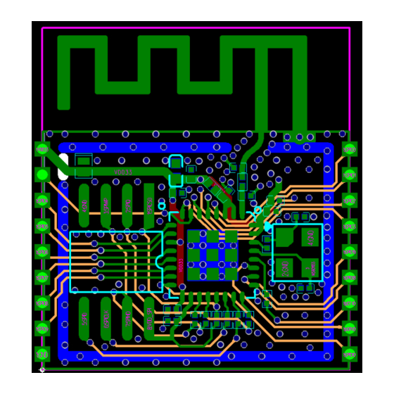
Page 17: Pcb Layout Design
If you design an on-board module, please pay attention to the placement of the module on the base board. The aim is to minimize the impact of the base board on the module’s antenna performance. Espressif Systems ESP32-C3 Family Hardware Design Guidelines V1.0... - Page 18 Figure 12: Placement of ESP32C3 Modules on Base Board. Antenna Feed Point on the Right Base board Figure 13: Placement of ESP32C3 Modules on Base Board. Antenna Feed Point on the Left Espressif Systems ESP32-C3 Family Hardware Design Guidelines V1.0 Submit Documentation Feedback...
- Page 19 If there is base board under the antenna area, it is recommended to cut it off to minimize its impact on the antenna. When designing an end product, pay attention to the impact of enclosure on the antenna. Espressif Systems ESP32-C3 Family Hardware Design Guidelines V1.0...
-
Page 20: Power Supply
• As shown in Figure 16, we recommend connecting the capacitor to ground in the LC filter circuit near pin 2 and pin 3 (analog power supply pins) to the third and fourth layer through a via, and maintaining a keep-out area on other layers. Espressif Systems ESP32-C3 Family Hardware Design Guidelines V1.0 Submit Documentation Feedback... -
Page 21: Crystal
• As the crystal is a sensitive component, do not place any magnetic components nearby that may cause interference (e.g. large inductance component), and ensure that around the crystal is a clean large ground plane. Espressif Systems ESP32-C3 Family Hardware Design Guidelines V1.0 Submit Documentation Feedback... - Page 22 A π-type matching circuit should be reserved on the RF trace and placed close to the chip. • The RF trace should have consistent width and not branch out. It should be as short as possible with dense ground vias around for inteference shielding. Espressif Systems ESP32-C3 Family Hardware Design Guidelines V1.0 Submit Documentation Feedback...
- Page 23 . • For designing the RF trace at 50 Ω single-ended impedance, please refer to the PCB stack-up design shown in Figure 20. Espressif Systems ESP32-C3 Family Hardware Design Guidelines V1.0 Submit Documentation Feedback...
-
Page 24: Flash
The series resistor on the U0TXD line needs to be placed close to the chip and away from the crystal. The U0TXD and U0RXD traces on the top layer should be as short as possible, surrounded by ground copper and ground vias. Espressif Systems ESP32-C3 Family Hardware Design Guidelines V1.0 Submit Documentation Feedback... -
Page 25: Typical Layout Problems And Solutions
As TX and RX share the antenna path, good TX performance indicates proper RF impedance matching. The reason of low RX sensitivity might lie in coupling of high-frequency interference signals to the antenna. In this Espressif Systems ESP32-C3 Family Hardware Design Guidelines V1.0... - Page 26 PCB layout. Solution: Keep the antenna away from crystals. Do not route high-frequency signal traces close to the RF trace. For details, please see Section 3. Espressif Systems ESP32-C3 Family Hardware Design Guidelines V1.0 Submit Documentation Feedback...
-
Page 27: Hardware Development
• The serial port cannot be used to print log and download firmware simultaneously. 4.2 Development Boards Built around ESP32C3 Family of Chips For latest information about ESP32-C3 development boards, please check Development Boards section of Espressif website. Espressif Systems ESP32-C3 Family Hardware Design Guidelines V1.0 Submit Documentation Feedback... -
Page 28: Revision History
Revision History Revision History Date Version Release notes 2021-05-28 V1.0 Official release 2021-04-09 V0.5 Preliminary release Espressif Systems ESP32-C3 Family Hardware Design Guidelines V1.0 Submit Documentation Feedback... -
Page 29: Solutions, Documentation And Legal Information
Sales and Technical Support • Sales Questions MustHave Resources • Technical Inquiries • SDKs and Demos • Get Samples • APPs Developer Zone • Tools • ESP32 Forum • Espressif Systems ESP32-C3 Family Hardware Design Guidelines V1.0 Submit Documentation Feedback... - Page 30 The Wi-Fi Alliance Member logo is a trademark of the Wi-Fi Alliance. The Bluetooth logo is a registered trademark of Bluetooth SIG. All trade names, trademarks and registered trademarks mentioned in this document are property www.espressif.com of their respective owners, and are hereby acknowledged. Copyright © 2021 Espressif Systems (Shanghai) Co., Ltd. All rights reserved.
Need help?
Do you have a question about the ESP32-C3FH4 and is the answer not in the manual?
Questions and answers