OHAUS Defender Series Service Manual
Hide thumbs
Also See for Defender Series:
- User manual ,
- Instruction manual (76 pages) ,
- Assembly instructions manual (55 pages)

Related Manuals for OHAUS Defender Series


Summary of Contents for OHAUS Defender Series
- Page 1 99 Washington Street Melrose, MA 02176 Phone 781-665-1400 Toll Free 1-800-517-8431 Visit us at www.TestEquipmentDepot.com Defender Series Base Service Manual...
-
Page 2: Table Of Contents
Safety Precaution ..........................3 Service Facilities ........................... 3 Tools and Test Equipment Required ..................... 4 Test Masses Required .......................... 4 Service Strategy ............................ 4 Physical Description: Model Defender Series Base ................4 Specifications ............................5 1.10 How Load Cells Operate ........................9 1.11 Load Cell Connection .......................... -
Page 3: Chapter 1 Introduction
CHAPTER 1 INTRODUCTION Introduction This service manual contains the information needed for diagnosis and repair of Ohaus Defender series Bases. The contents of this manual are contained in five chapters: Chapter 1 Introduction – Contains information regarding service facilities, tools and test equipment, test masses, specifications, service strategy, and the mechanical and electronic operation of the Base. -
Page 4: Safety Precaution
Safety Precaution For AC mains powered models: - Verify that the local AC power supply is within the input voltage range printed on the equipment’s data label. - Only connect the AC power cord to a compatible grounded electrical outlet. ... -
Page 5: Tools And Test Equipment Required
7. A calibrated Torque Wrench N.m. – Ft/Lbs Test Masses Required The masses required to test the Ohaus Defender series Bases when connected to an Indicator must meet the requirements of ASTM Class or OIML. Mass values 3kg to 600kg, depending on the Base model. The full scale rated capacity of the Base should be used for Span calibration. -
Page 6: Specifications
Specifications Complete specifications for the Ohaus Defender series Bases are listed in Table 1-1. When a Base has been serviced, it must meet the specifications listed in the table. Before servicing the Base, determine what specifications are not met. TABLE 1-1. SPECIFICATIONS FOR DEFENDER SERIES BASES... - Page 7 MODEL D50RTX D125RTX D250RTX D50RQV D125RQV D250RQV D500RQV D125RTV D250RTV D500RTV 100 lb / 250 lb / 500 lb / 100 lb / 250 lb / 500 lb / 1000 lb / 250 lb / 500 lb / 1000 lb / Capacity 50kg 125 kg...
- Page 8 MODEL D2WQS D5WQS D12WQS D12WQR D25WQR D50WQR D25WQL D50WQL D125WQL 5 lb / 10 lb / 25 lb / 25 lb / 50 lb / 100 lb / 50 lb / 100 lb / 250 lb / Capacity 2.5 kg 5 kg 12.5 kg 12.5 kg...
- Page 9 MODEL D50WTX D125WTX D250WTX D50WQV D125WQV D250WQV D500WQV 100 lb / 250 lb / 500 lb / 100 lb / 250 lb / 500 lb / 1000 lb / Capacity 50 kg 125 kg 250 kg 50 kg 125 kg 250 kg 500 kg Approved Resolution...
-
Page 10: How Load Cells Operate
How Load Cells Operate Load Cells convert force into a signal. The Defender Series Bases have a Strain Gauge Load Cell, which is made from a metal beam with holes drilled in it. Strain gauges are affixed to the beam at the top and bottom to measure changes in the beam due to deflection. -
Page 11: Load Cell Connection
Strain Gauges +Excitation Tension (Supply) Compression INPUT(volts) LOADCELL 2 mV/V Compression Tension 4 strain gauges – Excitation (Supply) connected as a Wheatstone Bridge +Sig OUTPUT (milli volts) – Figure 1-3. Route of electrical Load Cell input and output through Wheatstone Bridge circuit. A Load Cell is a force sensor, which receives a voltage (excitation) from a regulated power source in the Indicator, and sends back a low-voltage milli-volt (mV) relative to the force applied. - Page 12 Type2. DxxxRxx Bases FUNCTION WIRE COLOR + Excitation Green - Excitation Black + Signal White - Signal + Sense Blue - Sense Brown Shield Yellow Defender™ Series Bases Service Manual...
-
Page 13: Chapter 2 Troubleshooting
CHAPTER 2 TROUBLESHOOTING Troubleshooting This section of the manual provides guidelines for evaluating the condition and performance of a Base unit, and a standard troubleshooting methodology to follow. 2.1.1 Checking Load Cells for Trouble Visual Check: Examine the Load Cell for signs of bending, twisting or corrosion. –... -
Page 14: Chapter 3 Maintenance And Repair Procedures
CHAPTER 3 MAINTENANCE AND REPAIR PROCEDURES Preventive Maintenance Ohaus bases should be carefully handled, stored in a clean, dry area, and cleaned periodically. Follow these precautionary steps: – When a base has had chemicals or liquids spilled on it, all exterior surfaces should be cleaned as soon as possible with warm water on a damp cloth. -
Page 15: Overload Stop Adjustment
3. Tighten the Jam Nut and re-check the Gap. 4. Re-adjust if necessary. 5. Cover the Platform and check for full capacity. (See Table 3-1 for Gap settings.) TABLE 3-1. OVERLOAD GAP SETTINGS FOR DEFENDER SERIES BASES Overload Overload Stop... - Page 16 D15RTDR D30RTDR D15RQDL D30RQDL D60RQDL D15WQDL 400 x 400 D15WQL 15.7" x 15.7" D30WQDL D30WQL D60WQDL D60WQL D50RQL D125RQL 457 x 457 D25WQL 18" x 18" D50WQL D125WQL D60RTDL D150RTDL D60WTDL D150WTDL 400 x 500 15.7" x 19.6" D60RTL D150RTL D60WTL D150WTL D50RTX...
- Page 17 D125RTV D150RTDV D250RTV D300RTDV 600 x 800 D500RTV 23.6" x 31.5" D600RTDV D150WTDV D300WTDV D600WTDV Defender™ Series Bases Service Manual...
-
Page 18: Chapter 4 Testing
CHAPTER 4 TESTING Testing Before and after servicing a Defender series Base, conduct Load Cell Resistance Checks, Calibration using an external Indicator, and Performance Tests to confirm that the base meets specifications. Allow time for the base to stabilize after moving it from an area which is at a different temperature than the area where it is to be operated. -
Page 19: Consistency Check
4-6mv 9-11mv Performance Tests Accurate performance of the Defender series Bases is determined by two performance tests. The displayed readings are compared with the tolerances listed in Table 1-1. NOTE: The following performance tests are used to evaluate base operation before and after repairs. -
Page 20: Off Center Load (Shift) Test
4.5.1 Off Center Load (Shift) Test The Off Center Load (Shift) Test is made before and after a Base has had the Load Cell replaced and adjustments have been made that affect its performance. The Off Center Load Test verifies that all sections of the Base weigh within specified tolerance. -
Page 21: Adjusting Off Center Load
4.5.2 Adjusting Off Center Load If the Off Center Load (Shift) is excessive, perform adjustment as follows: Top view of Load Cell Side view of Load Cell Figure 4-2. Off Center Load adjustment points. 1. Place the test weight in the center of the Platform. 2. -
Page 22: Full Load Test
ATTENTION: In all cases where a part is replaced, the base must be thoroughly checked after the replacement is made. The base MUST meet the parameters of all applicable specifications in this manual. If further technical information is needed, please contact your local Ohaus office, or: Ohaus Corporation 7 Campus Drive, Suite 310... -
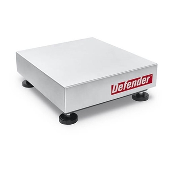
Page 23: Chapter 5 Parts Identofication
CHAPTER 5 PARTS IDENTOFICATION Defender series Base: Carbon Steel model Figure 5-1. Defender series Base: D52 RQR Defender™ Series Bases Service Manual... - Page 24 Drawing Item Part Number Description Remarks Pan, 305x305, SST, D52 30427798 Rubber Support, CS Base, D52 30427800 Foot CHII 71125009 Hardware Kit, R Base, D52 30427806 Load Cell 0785-22kg 2m 30427876 For D12RQR 30427877 Load Cell 0785-50kg 2m C3.5 For D25RQR 30448396 Load Cell 0785-50kg 2m C3MI For D30RQR...
-
Page 25: Defender Series Base: Stainless Steel Model
Defender series Base: Stainless Steel model Figure 5-2. Defender series Base: D52 WQR Defender™ Series Bases Service Manual... - Page 26 Box Complete, R, Big, D52 NOTE: When replacement parts are needed, refer to the spare part list for the model you are servicing. Parts lists are available from your local Ohaus office. To locate your nearest office, visit www.Ohaus.com. Defender™ Series Bases Service Manual...
-
Page 27: Appendix A. Glossary
V output over full range, they will quote the milli-Volt output per volt of excitation, or in its short form, mv/V. Most Ohaus Indicators provide an excitation voltage of 5 Volts dc. - Page 28 99 Washington Street Melrose, MA 02176 Phone 781-665-1400 Toll Free 1-800-517-8431 Visit us at www.TestEquipmentDepot.com *30479276A* 30479276A © 2018 OHAUS Corporation, all rights reserved...
Need help?
Do you have a question about the Defender Series and is the answer not in the manual?
Questions and answers