
Related Manuals for OHAUS Defender 5000 Series


Summary of Contents for OHAUS Defender 5000 Series
- Page 1 99 Washington Street Melrose, MA 02176 Phone 781-665-1400 Toll Free 1-800-517-8431 Visit us at www.TestEquipmentDepot.com Defender 5000 Indicators Instruction Manual TD52P TD52XW...
-
Page 3: Table Of Contents
Defender 5000 Indicators EN-1 TABLE OF CONTENTS 1. INTRODUCTION ..........................4 1.1 Safety Precautions ........................4 1.1.1 Relay Option Safety Precautions ..................4 1.2 Overview of Parts and Controls ....................5 1.3 Control Functions ........................8 2. INSTALLATION ..........................9 2.1 Unpacking ............................ - Page 4 EN-2 Defender 5000 Indicators 3.7 Weighing Unit ..........................26 3.7.1 Gram (g) ..........................26 3.7.2 Kilogram (kg) ........................27 3.7.3 Pound (lb) ........................... 27 3.7.4 Ounce (oz) .......................... 27 3.7.5 Pound: Ounce (lb: oz) ......................27 3.7.6 Tonne (Metric Tonne) ......................27 3.7.7 Ton (Short Ton)........................
- Page 5 Defender 5000 Indicators EN-3 5.2 RS232 Interface ......................... 50 5.3 Connecting to a Computer ......................50 5.4 Connecting to a Serial Printer ....................50 5.5 Printouts ............................ 50 5.6 Printout Examples ........................51 6. MICRO SD CARD ........................... 52 6.1 Library ............................52 6.2 User ............................
-
Page 6: Introduction
EN-4 Defender 5000 Indicators 1. INTRODUCTION This manual contains installation, operation and maintenance instructions for the TD52P and TD52XW Indicators. Please read this manual completely before installation and operation. 1.1 Safety Precautions For safe and dependable operation of this equipment, please comply with the following safety precautions: ... -
Page 7: Overview Of Parts And Controls
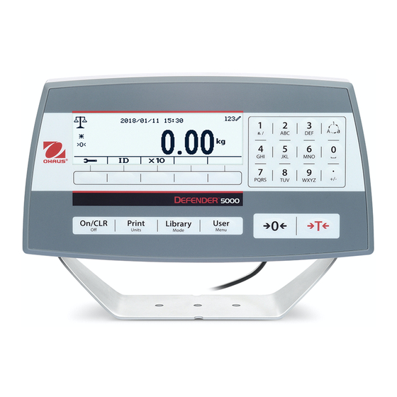
Defender 5000 Indicators EN-5 1.2 Overview of Parts and Controls TABLE 1-1 TD52P PARTS Item Description Data Label Front Housing Control Panel Mounting Bracket Screws (4) Adjusting Knobs (2) Security Screw Accessory Cover Rear Housing Power Connector RS232 Connector Load Cell Connector Figure 1-1 TD52P Indicator... - Page 8 EN-6 Defender 5000 Indicators 1.2 Overview of Parts and Controls (Cont.) TABLE 1-2 TD52XW PARTS Item Description Control Panel Front Housing Screws (6) Adjusting knobs (2) Rear Housing Mounting Bracket Load Cell Connector Strain Relief for Option Power Cord Strain Relief for Option Figure 1-2 TD52XW Indicator...
- Page 9 Defender 5000 Indicators EN-7 Controls 1.2 Overview of Parts and (Cont.) Figure 1-3 Main PC Board TABLE 1-3 MAIN PC BOARD Item Description IO/Analog/RS232-RS485-USB Device connector (J11) Micro-SD Card slot (J8) Rechargeable Battery Pack connector (J9) USB Host/Ethernet connector (J4) Security Switch connector (SW1) Load Cell connector (J12) RS232 connector (J5)
-
Page 10: Control Functions
EN-8 Defender 5000 Indicators 1.3 Control Functions Button Action Short press: If the terminal is Off, power on the terminal; if the terminal is On, clear the data input. Long press: Power off the terminal. Short press: Send the current display value to RS232 port or Option when properly enabled. -
Page 11: Installation
2.2 External Connections 2.2.1 Scale Base with Connector OHAUS bases with a connector can be attached to the external load cell connector (Figure 1-1, item 12). To make the connection, plug the base connector onto the external load cell connector. Then rotate the base connector’s locking ring clockwise. -
Page 12: Internal Connections
EN-10 Defender 5000 Indicators 2.3 Internal Connections Some connections require the housing to be opened. 2.3.1 Opening the Housing CAUTION: ELECTRICAL SHOCK HAZARD. REMOVE POWER CONNECTIONS TO THE INDICATOR BEFORE SERVICING OR MAKING INTERNAL CONNECTIONS. THE HOUSING SHOULD ONLY BE OPENED BY AUTHORIZED AND QUALIFIED PERSONNEL, SUCH AS AN ELECTRICAL TECHNICIAN. - Page 13 Defender 5000 Indicators EN-11 To install the ferrite, simply route the cable through the center of the core and then take one wrap around the outside of the core and route the cable through the center again. Either the complete cable or the individual wires can be wrapped through the ferrite.
-
Page 14: Rs232 Interface Cable To Td52Xw
EN-12 Defender 5000 Indicators After wiring is completed, replace the indicator housing screws. Make sure the liquid-tight connector is properly tightened. 2.3.3 RS232 Interface Cable to TD52XW Pass the optional RS232 cable through the strain relief (Figure 1-2, item 10) and attach it to terminal block J5 (Figure 1-3, item 7). -
Page 15: Td52Xw Rear Housing Orientation
Defender 5000 Indicators EN-13 2.4 TD52XW Rear Housing Orientation The TD52XW is delivered in the wall mount orientation with the connections exiting below the display. The rear housing may be reversed so the connections exit above the display when the TD52XW is placed horizontally on a bench. -
Page 16: Settings
EN-14 Defender 5000 Indicators 3. SETTINGS 3.1 Menu Structure TABLE 3-1 MENU STRUCTURE Calibration Setup Read Out Application Mode Zero Capacity Unit Stability Weighing Span Range Zero Range Counting Linearity >|1|< Capacity Filter Level Check >|1|<Graduation Auto Zero Track Percent Capacity &... - Page 17 Defender 5000 Indicators EN-15 Unit Communication Alt Tare CMD Alt Zero CMD Reset Assignment Select Template Print Setup Edit Template Edit String Reset Host Name MAC Address Port Version DHCP IP Address Subnet Mask Configuration Gateway Primary DNS Secondary Ethernet* Alt Print CMD Alt Tare CMD Alt Zero CMD...
- Page 18 * Sub- menu for options will be active only when the specific board is installed. The Bluetooth® word mark and logos are registered trademarks owned by Bluetooth SIG, Inc. and any use of such marks by OHAUS is under license.
-
Page 19: Menu Navigation
Defender 5000 Indicators EN-17 3.2 Menu Navigation To enter the Main Menu, press the button from any application home screen. Changing Settings To change a menu setting, navigate to that setting using the following steps: 1. Enter the Menu From any Application screen, press the button. -
Page 20: Span Calibration
EN-18 Defender 5000 Indicators Zero Calibration is on the top of the list of Calibration by default. Just press the Softkey corresponding to the icon to initiate Zero Calibration. Clear the pan and then press the Softkey corresponding to the icon The message 'Completed' will be displayed on the screen. -
Page 21: Linearity Calibration
Defender 5000 Indicators EN-19 A suggestive message shows on the screen. The message 'Completed' will be displayed on the screen. Exit Span Calibration by pressing the Softkey corresponding to the icon To return to the Main Menu, press the Softkey corresponding to the icon Note: Span Calibration should be performed after Zero Calibration. -
Page 22: Geo Adjustment
EN-20 Defender 5000 Indicators Put the calibration mass on the pan, and then press the Softkey corresponding to the icon confirmation. To change to a different calibration point, input the value desired, and then place the corresponding weight on the pan for calibration. The message 'Completed' will be displayed on the screen. -
Page 23: Setup Menu
Defender 5000 Indicators EN-21 3.4 Setup Menu When the Indicator connects to a scale base for the first time, enter this menu to set the Capacity Unit, Range, Capacity and Graduation. Default settings are bold. Setup Options Capacity Unit g, kg, t (Metric Tonne), lb, ton (Short Ton) Range Single Interval, Dual Interval >|1|<... -
Page 24: Capacity
EN-22 Defender 5000 Indicators 3.4.3 Capacity Set the scale capacity from 1 to 999999. >|1|< Capacity Specify the weight capacity for interval 1. If Single interval is enabled, this will be the scale capacity. If Dual interval is enabled, this will be the first range. >|2|<... -
Page 25: Key Beep
Defender 5000 Indicators EN-23 3.4.8 Key Beep Set how the beeper sounds when a key is pressed. Off = no sound On = sound 3.4.9 Transaction Counter The transaction counter is a seven-digit counter that tracks the total transactions. When the value reaches 9,999,999, the next transaction causes a roll-over to 0000001. -
Page 26: Zero Range
EN-24 Defender 5000 Indicators 3.5.2 Zero Range Set the percentage of scale capacity that may be zeroed. 100% NOTE: The setting is forced and locked to 2% when the Security Switch is set to the locked position. 3.5.3 Filter Level Set the amount of signal filtering. -
Page 27: Adjust Contrast
Defender 5000 Indicators EN-25 3.5.8 Adjust Contrast Set the contrast degree of the display. 3.5.9 Reset Reset all settings to factory default settings. Yes = Reset. No = Do not reset. NOTE: If the Security Switch is set to ON, Stability, Zero Range, Filter Level and Auto Zero Track settings are not reset. -
Page 28: Weighing Unit
EN-26 Defender 5000 Indicators For more details, see the table below. Application Mode Options (bold is default) & Discrete I/O Enable On, Off Discrete Input1 Off, Zero, Tare, Clear Tare, Print, Unit, Accumulate Discrete Input2 Off, Zero, Tare, Clear Tare, Print, Unit, Accumulate Weighing Off, Overload, Underload, Zero Discrete Output1... -
Page 29: Kilogram (Kg)
Defender 5000 Indicators EN-27 3.7.2 Kilogram (kg) Set the status. Off = Disabled On = Enabled 3.7.3 Pound (lb) Set the status. Off = Disabled On = Enabled 3.7.4 Ounce (oz) Set the status. Off = Disabled On = Enabled 3.7.5 Pound: Ounce (lb: oz) Set the status. -
Page 30: Glp/Gmp Menu
EN-28 Defender 5000 Indicators Note: Custom Unit is locked at Off position when the Security Switch is set to the locked position. Custom Unit is not available when Range is set to Dual interval. Set the status. Off = Disabled On = Enabled 3.8 GLP/GMP Menu Enter this menu to set the Good Laboratory Practice (GLP) or Good Manufacturing Practice (GMP) -
Page 31: Communication
Defender 5000 Indicators EN-29 3.9 Communication Enter this menu to define external communication methods and to set printing parameters. Data may be output to either a printer or PC. Factory default settings are shown in bold. 3.9.1 RS232/2nd RS232 Configuration Communication Options(bold is default) 300, 600, 1200, 2400, 4800, 9600, 19200,... -
Page 32: Print Setup Of Rs232/2Nd Rs232
EN-30 Defender 5000 Indicators 3.9.1.3 Stop Bits Set the stop bits. 1 BIT 2 BIT 3.9.1.4 Handshake Set the flow control method. NONE = no handshaking XON/XOFF = XON/XOFF handshaking HARDWARE = hardware handshaking (COM1 menu only) 3.9.1.5 Alternate Print Command Set the alternate command character for Print. - Page 33 Defender 5000 Indicators EN-31 3.9.2.5 MT-Continuous If MT-Continuous is selected, the print output will be in the MT-Continuous format. CONTINUOUS = printing occurs continuously. Note: Refer to Appendix A for MT-Continuous format. 3.9.2.6 OH-Continuous If OH-Continuous is selected, the print output will be in the OH-Continuous format. Note: Refer to Appendix A for OH-Continuous format.
-
Page 34: Rs485 Configuration
Select the string number in the first selection box then any existing data for that string will be shown in the second entry box. Using the alphanumeric keys, enter or edit the characters to be used as the selected string. String 1 = OHAUS (Default) String 2 = T52 (Default) 3.9.2.12 Reset... -
Page 35: Operation
Defender 5000 Indicators EN-33 4. OPERATION The scale can be configured to operate in up to 5 Application modes (Scale can be set to have 1 or more Applications modes active). Press the button Mode to select an activated application. The current application will be shown in the upper left corner of the home screen. -
Page 36: Accumulation
EN-34 Defender 5000 Indicators 4.1.3 Accumulation To start Accumulate weighing data, place the object on the pan and press the Softkey corresponding icon accumulation icon will start blinking. The load to be accumulated has to be >= 5d and the next accumulation can only start once the pan has been cleared. -
Page 37: Input/Output (I/O) Setup
Defender 5000 Indicators EN-35 4.1.5 Input/Output (I/O) Setup The I/O’s setup can be customized for various user preferences. The I/O’s setup is defined below (defaults in Bold). Item Available Settings On, Off Enable Discrete Input 1 Off, Zero, Tare, Clear Tare, Print, Unit, Accumulate Discrete Input 2 Off, Zero, Tare, Clear Tare, Print, Unit, Accumulate Discrete Output 1... -
Page 38: Counting
EN-36 Defender 5000 Indicators 4.2 Counting Use this application to count samples of uniform weight. Press button until icon corresponding to Counting is displayed in the screen. The default (or last) Average Piece Weight (APW) is displayed. Set the APW value according to section 4.2.1 and then place objects on the pan to display the number of pieces. -
Page 39: Application Setup
Defender 5000 Indicators EN-37 2. Calculating an APW Method 1 Place the sample on the pan and then key in the number of pieces using the alphanumerical keypad. Press the Softkey corresponding to the icon for confirmation. The terminal will calculate the new APW using the number of pieces. -
Page 40: Accumulation
EN-38 Defender 5000 Indicators The Counting Configurations are defined below (defaults in Bold). Configure Item Option(Bold is Description default) Auto Tare Off/On Off: Auto tare is turned off. On: The first stable weight (>=5d) will be tared as a container automatically. -
Page 41: Check
Defender 5000 Indicators EN-39 Press the button to enter the Main Menu. With the button corresponding to the icon , go down the list and highlight Application Mode. Enter this sub-menu by pressing the button corresponding to the icon In the Application Mode menu enter the Counting sub-menu. -
Page 42: Check Counting
EN-40 Defender 5000 Indicators The Check Configurations are defined below (defaults in Bold). Configure Item Option(Bold is default) Description Check Weighting/ Check Check weighing mode Check Mode Counting Check counting mode Auto Tare Off/On Off: Auto tare is turned off. On: The first stable weight (>=5d) will be tared as a container automatically. -
Page 43: Application Setup
Defender 5000 Indicators EN-41 4.3.3 Application Setup The Application can be customized for various user preferences. Press the Softkey corresponding to the icon to enter Configuration Setup The Configuration Menu is now displayed. Select the list item and press the Softkey corresponding to the icon to change the setting as desired. -
Page 44: Input/Output (I/O) Setup
EN-42 Defender 5000 Indicators 4.3.4 Input/Output (I/O) Setup The I/O’s setup can be customized for various user preferences. The I/O’s setup is defined below (defaults in Bold). Item Available Settings Enable On, Off Discrete Input 1 Off, Zero, Tare, Clear Tare, Print, Unit, Accumulate Off, Zero, Tare, Clear Tare, Print, Unit, Accumulate Discrete Input 2 Discrete Output 1... -
Page 45: Establishing A Reference Weight
Defender 5000 Indicators EN-43 4.4.1 Establishing a Reference Weight There are 3 methods to establish a reference weight: Method 1 Key in the reference weight value using the alphanumerical keypad. Press the Softkey corresponding to the icon for confirmation. Method 2 Press the Softkey corresponding to the icon to enter the sub-menu for setting the reference weight... -
Page 46: Input/Output (I/O) Setup
EN-44 Defender 5000 Indicators Select the list item and press the Softkey corresponding to the icon to change the settings as desired. To return to the Application home screen, press the Softkey corresponding to the icon The Percent Configurations are defined below (defaults in Bold). Configure Item Option(Bold is default) Description... -
Page 47: Dynamic Weighing
Defender 5000 Indicators EN-45 In the Application Mode menu, enter the Percent sub-menu. Select the list item and press the Softkey corresponding to the icon to change the setting as desired. After completion of I/O’s setup, press the Softkey corresponding to the icon to return to the main application screen. - Page 48 EN-46 Defender 5000 Indicators The Dynamic Configurations are defined below (defaults in Bold). Configure Item Option(Bold is default) Description Dynamic Mode Count down/Continuous Count down: There is a countdown time. Continuous: There is no countdown time. Manual/ Manual: Operation Type Semi-Automatic/ Place load on the pan.
-
Page 49: Average Time Setup
Defender 5000 Indicators EN-47 Option(Bold is default) Configure Item Description Note: 1. The load to be accumulated has to be >= 5d. Another accumulation can't be done until the pan is cleared (< 5d). 2. Gross weight and net weight can't be accumulated together when the LFT is ON (no such limit when the LFT is OFF or the approved model is OIML). -
Page 50: Input/Output (I/O) Setup
EN-48 Defender 5000 Indicators Method 2 1. Use the alphanumerical keypad to key in the desired averaging time. 2. Once the value keyed in is displayed in upper left portion of the screen, press the Softkey corresponding to the icon 4.5.3 Input/Output (I/O) Setup The I/O’s setup can be customized for various user preferences. -
Page 51: Serial Communication
Table 5-1. The Indicator supports both MT-SICS and OHAUS commands. Commands listed in the following tables will be acknowledged by the indicator. To use the MT-SICS commands, send the command PSI. -
Page 52: Rs232 Interface
EN-50 Defender 5000 Indicators 5.2 RS232 Interface RS232 (DB9) Pin Connections: Pin 2: Scale transmit line (TxD) Pin 3: Scale receive line (RxD) Pin 5: Ground signal (GND) Pin 7: Clear to send (hardware handshake) (CTS) Pin 8: Request to send (hardware handshake) (RTS) Use the built-in RS-232 Port to connect either to a computer or a printer 5.3 Connecting to a Computer Connect to the computer with a standard (straight-through) serial cable. -
Page 53: Printout Examples
Note: The Termination Characters Carriage Return and Line Feed are appended to the printout. 5.6 Printout Examples Setup in Menu Print out {String 1} {New Line} OHAUS CORPORATION {String 2} {New Line} 7 Campus Drive {String 3} {New Line} Suite 310... -
Page 54: Micro Sd Card
EN-52 Defender 5000 Indicators 6. MICRO SD CARD SD Card Options(bold is default) Library Off, On Enable Off/Alibi/Editable Memory Link to RS232/2ndRS232/RS485/Ethernet/Wifi/USB device Enable Off, On User User Profiles Note: "SD Card" only displays when SD card is installed. It will format the SD Card when entering this submenu at first time. - Page 55 Defender 5000 Indicators EN-53 Enter Library Press the Library button to enter library screen. Create a new library Press Softkey corresponding to the icon . The length of PN and Name is up to 32 digits of alphanumeric characters. Search Library Press the Softkey corresponding to the icon Enter "PN"...
-
Page 56: User
EN-54 Defender 5000 Indicators If the number of the results reaches 4, the records with the PN includes string "12345" are listed in the result. If the user press Softkey corresponding to the icon , a new search will start. Recall Library Press the Softkey corresponding to the icon to recall library. - Page 57 Defender 5000 Indicators EN-55 New a User Press soft key "New" to enter new user screen. The first user must be admin user. The user name is unique. Search a User Press the Softkey corresponding to the icon to search the user. Input the "User Name"...
- Page 58 EN-56 Defender 5000 Indicators Edit & Delete a User Press the Softkey corresponding to the icon to enter the edit screen. The admin user can edit any user, and the supervisor just can edit operator. The admin user cannot change the role of the login user.
-
Page 59: Alibi
Defender 5000 Indicators EN-57 6.3 Alibi A SD memory card is necessary to use Alibi memory, or an error message will display (SD card is not installed). If the Alibi option is set On, the additional menu item Alibi Memory Record will display. Each time a demand print is triggered or a "P"... -
Page 60: Editable
EN-58 Defender 5000 Indicators 6.4 Editable Editable If the is set On, the submenu Link to will display. The 'Link to' contains RS232, 2 RS232, RS485, Ethernet, Wi-Fi and USB device. The default is RS232. The output printed to the interface above will be saved as a .txt file distinguished by month. For example, 201612.txt is the data printed to the interface during Dec. -
Page 61: Sealing
Defender 5000 Indicators EN-59 7.3 Sealing The local weights and measures official or authorized service agent must apply a security seal to prevent tampering with the settings. Refer to the illustrations below for sealing methods. Figure 7-1. TD52P Wire Seal Figure 7-2. -
Page 62: Troubleshooting
Agent. For Service assistance in the United States, call toll-free 1-800-526-0659 between 8:00 AM and 5:00 PM Eastern Standard Time. An OHAUS Product Service Specialist will be available to assist you. Outside the USA, please visit our website www.ohaus.com to locate the OHAUS office nearest... -
Page 63: Technical Data
Defender 5000 Indicators EN-61 9. TECHNICAL DATA 9.1 Specifications Materials TD52XW Housing: stainless-steel TD52P Housing: ABS plastic Display window: polycarbonate Keypad: polyester Ambient conditions The technical data is valid under the following ambient conditions: Ambient temperature: -10° C to 40° C / 14° F to 104° F Relative humidity: Maximum relative humidity 80% for temperatures up to 31°... -
Page 64: Accessories And Options
Interface, Analog output 30424404 Interface, RS232/RS485/USB 30424405 Rechargeable Li-ion Battery Kit 30424406 Interface, USB Host 30424021 Light Tower Kit, 3 Colors, OHAUS 30424022 In-use-cover Kit, TD52P 30424023 In-use-cover Kit, TD52XW 30424026 Wall Mount Kit, SST 30424027 Wall Mount Kit, CS... -
Page 65: Drawings And Dimensions
Defender 5000 Indicators EN-63 9.3 Drawings and Dimensions TD52P TD52XW... -
Page 66: Table Of Geo Values
EN-64 Defender 5000 Indicators 9.4 Table of Geo Values TABLE 9-4 GEO CODES Elevation in meters 1300 1625 1950 2275 2600 2925 3250 1300 1625 1950 2275 2600 2925 3250 3575 Elevation in feet 1060 2130 3200 4260 5330 6400 7460 8530 9600... -
Page 67: Compliance
This Class A digital apparatus complies with Canadian ICES-003 ISO 9001 Registration In 1994, OHAUS Corporation, USA, was awarded a certificate of registration to ISO 9001 by Bureau Veritus Quality International (BVQI), confirming that the OHAUS quality management system is compliant with the ISO 9001 standard’s requirements. - Page 68 Should this device be passed on to other parties (for private or professional use), the content of this regulation must also be related. Disposal instructions in Europe are available online at www.ohaus.com/weee. Thank you for your contribution to environmental protection.
-
Page 69: Appendices
Table 5-1. Non-significant weight data and tare data digits are transmitted as spaces. The continuous output mode provides compatibility with OHAUS products that require real-time weight data. the standard continuous output. Table 5-1 shows the format for the standard continuous output. - Page 70 EN-68 Defender 5000 Indicators Table 5-3: Status Byte B Bit Definitions Status Bits Function Bit 0 Gross = 0, Net = 1 Bit 1 Sign, Positive = 0, Negative = 1 Bit 2 Out of Range = 1 (Over capacity or Under Zero) Bit 3 Motion = 1, Stable = 0 Bit 4...
- Page 71 Defender 5000 Indicators EN-69 11.2 Appendix B MT-SICS Commands Command Function LEVEL Reset the scale Inquiry of all available SICS commands Inquiry of SICS level and SICS versions Inquiry of scale data Inquiry of scale software version Inquiry of serial number Send stable weight value Send weight value immediately Send weight value repeatedly...
- Page 72 OHAUS. In lieu of a properly returned warranty registration card, the warranty period shall begin on the date of shipment to the authorized dealer. No other express or implied warranty is given by OHAUS Corporation.
- Page 73 ® OHAUS and Defender are either registered trademarks or trademarks of OHAUS Corporation in the United States and/or other countries. 99 Washington Street Melrose, MA 02176 Phone 781-665-1400 Toll Free 1-800-517-8431 Visit us at www.TestEquipmentDepot.com *30430958* P/N 30430958A © 2018 OHAUS Corporation, all rights reserved.
Need help?
Do you have a question about the Defender 5000 Series and is the answer not in the manual?
Questions and answers