
Related Manuals for OHAUS Defender 5000 TD52P


Summary of Contents for OHAUS Defender 5000 TD52P
- Page 1 99 Washington Street Melrose, MA 02176 Phone 781-665-1400 Toll Free 1-800-517-8431 Visit us at www.TestEquipmentDepot.com Defender 5000 Indicators Service Manual TD52P TD52XW...
-
Page 2: Table Of Contents
TABLE OF CONTENTS INTRODUCTION ............................1 1.1 DEFINATION OF SIGNAL WARNING AND SYMBOLS ................1 1.1.1 Safety Precautions ..........................1 1.1.2 Relay Option Safety Precautions ......................1 1.2 SERVICE FACILITIES ..........................2 1.3 TOOLS AND TEST EQUIPMENT REQUIRED ..................2 1.3.1 Special Tools and Test Equipment List .................... - Page 3 2.4.1 Capacity Unit ............................. 18 2.4.2 Range ..............................18 2.4.3 Capacity ............................18 2.4.4 Graduation ............................18 2.4.5 Language ............................19 2.4.6 Power On Zero ..........................19 2.4.7 Power On Unit ........................... 19 2.4.8 Key Beep ............................19 2.4.9 Transaction Counter .......................... 19 2.4.10 Password ............................
- Page 4 2.8.7 Reset ..............................25 2.9 Communication ............................25 2.9.1 RS232/2 RS232 Configuration ....................... 25 2.9.2 Print Setup of RS232/2nd RS232 ..................... 27 2.9.3 RS485 Configuration ......................... 29 2.9.4 Ethernet Configuration ........................29 2.9.5 Wifi Configuration ..........................29 2.9.6 Bluetooth Configuration ........................29 2.9.7 Analog ...............................
-
Page 5: Introduction
INTRODUCTION This service manual contains the information needed to perform routine maintenance and service on the Defender 5000 Series Scales. There will be two parts for the service manual where first part will describe the service on the Indicator as this manual and second part would describe the service for the bases, please refer to Defender Series Base Service Manual. -
Page 6: Service Facilities
In order to properly service the Indicator, certain special tools and test items are required in addition to standard electronic tool kits. These items are listed as follows: 1.3.1 Special Tools and Test Equipment List 1. Ohaus Scale Base. 2. Load Cell Simulator optional. 3. Computer with RS232 Interface for testing the RS232 communications. -
Page 7: Standard Tools And Test Equipment List
1.3.2 Standard Tools and Test Equipment List 1. Standard Electronics Tool Kit 2. Digital Voltmeter (DVM), with clip on probes. Input impedance of at least 10 megohms in the 1 Volt dc position. 3. Soldering Iron, solder and flux remover. 1.4 OVERVIEW OF PARTS AND CONTROLS 1.4.1 TD52P TABLE 1-1... -
Page 8: Td52Xw
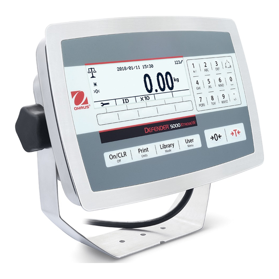
1.4.2 TD52XW TABLE 1-2 TD52XW PARTS Item Description Control Panel Front Housing Screw (6) Adjusting knob (2) Rear Housing Mounting Bracket Load Cell Connector Strain Relief for Option Power Cord Strain Relief for Option Figure 1-2 TD52XW Indicator Defender 5000 Indicators Service Manual... -
Page 9: Main Pc Board
1.4.3 MAIN PC BOARD Figure 1-3 Main PC Board TABLE 1-3 MAIN PC BOARD Item Description IO/Analog/RS232-RS485-USB Device (J11) SD Card (J8) Rechargeable Battery Pack (J9) USB Host/Ethernet (J4) Security Switch (SW1) Load Cell (J12) RS232 (J5) Load Cell (J3) Defender 5000 Indicators Service Manual... -
Page 10: Control Functions
1.5 CONTROL FUNCTIONS Button Action Short press: If the terminal is Off, power on the terminal; if the terminal is On, clear the data input. Long press: Power off the terminal. Short press: Send the current display value to RS232 port in the case where the "Communication ->... -
Page 11: External Connections
1.6.1 Scale Base with Connector Ohaus bases with a connector can be attached to the external load cell connector (Figure 1-1, item 12). To make the connection, plug the base connector onto the external load cell connector. Then rotate the base connector’s locking ring clockwise. -
Page 12: Scale Base Without Connector
TD52XW Remove the four hex head screws from the rear housing. Open the housing by carefully pulling the front housing forward. Once all connections are made, reattach the front housing. The screws should be tightened to 2.5 N•m (20-25 in-lb) torque to ensure a watertight seal. 1.7.2 Scale Base Without Connector For connecting bases (which do not have the connector) to a TD52P or TD52XW, a cable gland kit (P/N 30379716) is available as an accessory. - Page 13 Figure 1-6 Jumper Connections The TD52P and TD52XW terminals are designed to support both 2mV/V and 3mV/V load cells from the same circuitry. A load cell output rating selection jumper is not required. Figure 1-7 shows the terminal definitions for the analog load cell terminal strip. Note that when using four- wire load cells, jumpers must be placed between the +Excitation and +Sense terminals and between the Excitation and Sense terminals.
-
Page 14: Rs232 Interface Cable To Td52Xw
1.7.3 RS232 Interface Cable to TD52XW Pass the optional RS232 cable through the strain relief (Figure 1-2, item 10) and attach it to terminal block J5 (Figure 1-3, item 7). Tighten the strain relief to maintain a watertight seal. 1.7.4 MICRO SD Card Installation The SD memory card can be used for additional storage in the Checkweighing and Counting applications. -
Page 15: Settings
Figure 1-11 Mounting Bracket Dimensions 2 SETTINGS This section of the manual explains the Menu Structure of the Indicator. 2.1 Menu Structure TABLE 2-1 MENU STRUCTURE Calibration Setup Read Out Application Mode Zero Capacity Unit Stability Weighing Span Range Zero Range Counting Linearity >|1|<... - Page 16 Unit Communication Factor Select Template Exponent Edit Template Edit String Reset Reset Address Baud Rate Parity Stop Bit Configuration Handshake Alt Print CMD Alt Tare CMD RS485* Alt Zero CMD Reset Assignment Select Template Print Setup Edit Template Edit String Reset Host Name MAC Address...
-
Page 17: Menu Navigation
* Sub- menu for options will be active only when the specific board is installed. The Bluetooth® word mark and logos are registered trademarks owned by Bluetooth SIG, Inc. and any use of such marks by OHAUS is under license. -
Page 18: Calibration Menu
Changing Settings To change a menu setting, navigate to that setting using the following steps: 1. Enter the Menu From any Application screen, press the button. The Main Menu List appears on the screen. 2. Select the Sub-menu Scroll to the desired Sub-menu in the Main Menu List using the soft key corresponding to the icon Press the soft key corresponding to the icon to display the Sub-menu items. -
Page 19: Span Calibration
Clear the pan and then press the soft key corresponding to the icon The message 'Completed' will be displayed on the screen. Exit Zero Calibration by pressing the soft key corresponding to the icon To return to the Main Menu, press the soft key corresponding to the icon 2.3.2 Span Calibration Span Calibration uses one point. -
Page 20: Linearity Calibration
Exit Span Calibration by pressing the soft key corresponding to the icon To return to the Main Menu, press the soft key corresponding to the icon Note: Span Calibration should be performed after Zero Calibration. 2.3.3 Linearity Calibration Linearity calibration uses 3 calibration points. The full calibration point is established with a weight on the scale. -
Page 21: Geo Adjustment
Exit Linearity Calibration by pressing the soft key corresponding to the icon To return to the Main Menu, press the soft key corresponding to the icon 2.3.4 GEO Adjustment Set the GEO factor that corresponds to your location. GEO codes are numbered 0-31. Long press the button to enter the Main Menu. -
Page 22: Capacity Unit
Power On Zero Off, On Power On Unit Auto, kg, lb, g, oz, lb:oz, t, ton, c Key Beep Off, On Beep Volume Low, High Transaction Counter Off, On Next Transaction 1-9999999 Password Off, On Set Password xxxxxx Confirm Password xxxxxx Reset 2.4.1 Capacity Unit... -
Page 23: Language
>|1|<Graduation Specify the graduation for weighing range 1. If Single range is enabled, this will be the graduation for the entire weighing range of the scale. If Dual range is enabled, this will be the graduation used in the lower range. -
Page 24: Password
2.4.9.1 Next Transaction The value of the next transaction displays in the Next Transaction field. 2.4.10 Password Set the password. Off = the menu is accessed freely without password. On = the menu is accessed only after entering a password up to 6 digits. 2.4.11 Reset Reset the Setup menu to the factory defaults (except Range, Capacity and Graduation). -
Page 25: Auto Zero Tracking
Medium = normal stabilization time with normal stability. High = slower stabilization time with more stability. 2.5.4 Auto Zero Tracking Set the automatic zero tracking functionality. = disabled. 0.5division = the display will maintain zero until a change of 0.5 division per second has been exceeded. -
Page 26: Discrete I/O
2.6 Discrete I/O Long press the button to enter the Main Menu. Select Application Mode by pressing the soft key corresponding to the icon Press the soft key corresponding to the icon enter the sub-menu Application Mode. Enable The current selected application mode can't be set Off. Discrete I/O setup menus allow the configuration of 2 inputs and 4 outputs depending on different application mode. -
Page 27: Weighing Unit
Application Mode Options (bold is default) & Discrete I/O Off, Overload, Underload, Zero Discrete Output1 Discrete Output2 Off, Overload, Underload, Zero Discrete Output3 Off, Overload, Underload, Zero Off, Overload, Underload, Zero Discrete Output4 Reset 2.7 Weighing Unit Enter this menu to activate the desired units. Default settings are bold. NOTE: Due to national laws, the indicator may not include some of the units of measure listed. -
Page 28: Custom Unit (C)
2.7.8 Custom Unit (c) Use the Custom Unit to display weight in an alternative unit of measure. The custom unit is defined using a conversion factor, where the conversion factor is the number of custom units per gram expressed in scientific notation (Factor x 10^Exponent). -
Page 29: Time
2.8.4 Time Set the time. 24 hour format 00 to 23 = hour position 00 to 59 = minute position 2.8.5 Project ID Set the Project identification. Refer to Section 3.2 Menu Navigation to enter settings. 2.8.6 Scale ID Set the Project identification. Refer to Section 3.2 Menu Navigation to enter settings. - Page 30 Simple, Custom 1, Custom 2, Custom 3, Custom 4, Select Template Custom 5 Edit Template Field 1~ field 100 Edit String String 1~ String 10 Reset 2.9.1.1 Baud Rate Set the baud rate (bits per second). 1200 2400 4800 9600 19200 2.9.1.2 Parity Set the data bits and parity.
-
Page 31: Print Setup Of Rs232/2Nd Rs232
2.9.2 Print Setup of RS232/2nd RS232 2.9.2.1 Demand If Demand is selected, the sub-menu Stable Only will display. Set the printing criteria. OFF = values are printed immediately, regardless of stability. ON = values are printed only when the stability criteria are met. Note: For more detailed information, please refer to Section 5.3 Printout. - Page 32 2.9.2.9 Select Template This sub-menu is used to define the format of the data output to a printer or computer. Simple = only prints result and unit Custom 1 = customized printout format. If not customized, Simple template will be used Custom 2 = customized printout format.
-
Page 33: Rs485 Configuration
Select the string number in the first selection box then any existing data for that string will be shown in the second entry box. Using the alphanumeric keys, enter or edit the characters to be used as the selected string. String 1 = OHAUS (Default) String 2 = T52 (Default) 2.9.2.12 Reset... -
Page 34: Firmware Update
Expand reading is the internal calculation result, which should be up and down following with the Ramp changes. 2.10.3 Firmware Update Please refer to "APPENDIX C. Software Update via Micro SD card" for the software update. 2.10.4 Factory Reset Reset the indicator the initial setup. 2.10.5 Board Info Scroll down the menu to the Board Info, enter this Menu you will find the software version and the PCB series number... -
Page 35: Troubleshooting
For Service assistance in the United States, call toll-free 1-800-526-0659 between 8:00 AM and 5:00 PM Eastern Standard Time. An Ohaus Product Service Specialist will be available to assist you. Outside the USA, please visit our website www.ohaus.com to locate the Ohaus office nearest you. -
Page 36: Technical Data
TECHNICAL DATA 4.1 Specifications Materials TD52XW Housing: stainless-steel TD52P Housing: ABS plastic Display window: polycarbonate Keypad: polyester Ambient conditions The technical data is valid under the following ambient conditions: Ambient temperature: -10° C to 40° C / 14° F to 104° F Relative humidity: Maximum relative humidity 80% for temperatures up to 31°... -
Page 37: Accessories And Options
Interface, Analog output 30424404 Interface, RS232/RS485/USB 30424405 Rechargeable Li-ion Battery Kit 30424406 Interface, USB Host 30424021 Light Tower Kit, 3 Colors, OHAUS 30424022 In-use-cover Kit, TD52P 30424023 In-use-cover Kit, TD52XW 30424026 Wall Mount Kit, SST 30424027 Wall Mount Kit, CS... -
Page 38: Table Of Geo Values
4.3 Table of Geo Values TABLE 4-3 GEO CODES Elevation in meters 1300 1625 1950 2275 2600 2925 3250 1300 1625 1950 2275 2600 2925 3250 3575 Elevation in feet 1060 2130 3200 4260 5330 6400 7460 8530 9600 10660 1060 2130 3200... -
Page 39: Replacing Major Components (Indicator)
REPLACING MAJOR COMPONENTS (INDICATOR) Ohaus Indicators are precision instruments and should be carefully handled, stored in a clean, dry, dust-free area, and cleaned periodically. Follow these precautionary steps: – When an Indicator has had chemicals or liquids spilled on it, all exterior surfaces should be cleaned as soon as possible with warm water on a damp cloth. - Page 40 4. Remove the Seal and 3 screws for the LFT TD52P Wire Seal TD52P Paper Seal 5. Carefully separate the Top Housing and Bottom Housing. Defender 5000 Indicators Service Manual...
- Page 41 6. Remove the power connector, load cell connector, LCD connect and function label connector from the main PCBA 7. Remove the 4 screws from the PCB and securely remove the main PCBA from the bottom housing. CAUTION When handling the PCB, grasp it by the edges only! Do not touch the foil side.
- Page 42 3. Carefully separate the Top Housing and Bottom Housing. 4. * If the indicator comes with the optional RS232 kit kindly remove from the PCB cover via removing 2 screws and the cable to the PCBA. Defender 5000 Indicators Service Manual...
- Page 43 5. Remove the screws on the red pad and move the red pad in the direction as picture shown. 6. Remove the screw in the red circle and the power connectors from main PCBA and loadcell cable, then separate the cover of main PCBA (pry the side of cover edge slightly by the slot type screwdriver and lift the cover as picture shown) Defender 5000 Indicators Service Manual...
-
Page 44: Lcd Replacement
7. Remove LCD and Keypad cables and the 3 screws from the PCBA and securely remove the main PCBA from the bottom housing. CAUTION When handling the PCB, grasp it by the edges only! Do not touch the foil side. Static discharge may damage some components. 8. -
Page 45: Cable Set Replacement
3. Take out the LCD replace with the new one 5.2.3 TD52XW 1. Follow the Steps 1~7 of the PCB Replacement 5.1.2. 2. Remove 5 screws on the PCBA Support 3. Take out the LCD and replace with the new one 5.3 Cable Set Replacement Cables set information: Part Number... -
Page 46: Function Label Replacement
Part Number Description 30427858 Loadcell Connector, Short, TD52 30427859 Loadcell Connector, Long, TD52 1. Open the Housing. Disconnect the cables from any of the connectors (Battery, Load Cell, AC outlet) for which the cable set is to be replaced. In the case of the TD52’s battery, remove the quick-connect tabs that hold the cables in place. -
Page 47: Transformer Replacement
4. Remove the protective backing from the back of the new Function Label. Carefully position it on the Top Housing, starting at the bottom of the cover. Use a rolling motion to smooth it into position. 5. Reconnect the Function Label cable and reserve step 1 to complete the indicator assembly. - Page 48 8. Secure the Transformer with four screws, and reserve step 2 for Housing assembly 9. Connect the Indicator to AC power and test it. Note: Kindly take note of the cable routing from the Transformer within the bottom housing. Defender 5000 Indicators Service Manual...
-
Page 49: Appendix A. Configuring The Main Pcba
Once a new Main PCBA is installed one will need to configure the new Main PCBA according to their region. 1. Down load and install OHAUS Service and Repair Tools (Version 2.2.0.0 and later). 2. Open the software and select 'Repair Tool' and click 'Next' 3. - Page 50 8. Turn OFF and ON the indicator and check if the configuration is correct. 9. If the process fail kindly check the below. * The communication cable pin configuration. * The Indicator Protocol setting. Defender 5000 Indicators Service Manual...
-
Page 51: Appendix B. Software Update Via Service Tool
For TD52XW model, need the RS232 cable which in included in the cable set kit 30427860, please connect the RS232 cable to the socket as the picture below. 1. Down load and install OHAUS Service and Repair Tools (Version 2.2.0.0 and later). 2. Open the software and select 'Repair Tool' and click 'Next' 3. - Page 52 7. Cycle the power and press the 'ON' button, follow by the instruction in the picture below 8. You will see the below window screen when it's in the process of the software download. 9. You will see the below window screen when the software download is completed successfully. Defender 5000 Indicators Service Manual...
-
Page 53: Appendix C. Software Update Via Micro Sd Card
APPENDIX C. SOFTWARE UPDATE VIA MICRO SD CARD Note: Need prepare the Micro SD card for this process. 1, Create the new folder "D5000" under the root folder of the Micro SD, and "Update" under "D5000" 2, Copy the mot file in the folder "Update" with the name "30427649.mot" 3, Insert the Micro SD card into the SD card Slot (Make sure indicator is powered off for this step) TD52P TD52XW... - Page 54 7, The indicator will be switched off automatically, when it's done with the software upgrading 8, Switch on the indicator to check the software version, when program startup. Defender 5000 Indicators Service Manual...
- Page 55 99 Washington Street Melrose, MA 02176 Phone 781-665-1400 Toll Free 1-800-517-8431 Visit us at www.TestEquipmentDepot.com *30479277A* 30479277A © 2018 OHAUS Corporation, all rights reserved...
Need help?
Do you have a question about the Defender 5000 TD52P and is the answer not in the manual?
Questions and answers