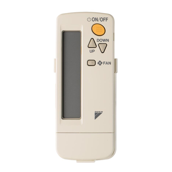
Daikin BRC7EA629 Installation Manual
Wireless remote controller kit
Hide thumbs
Also See for BRC7EA629:
- Operation manual (20 pages) ,
- Installation manual (12 pages) ,
- Operation manual (20 pages)
Summary of Contents for Daikin BRC7EA629
- Page 1 Installation manual Wireless Remote Controller Kit BRC7EA628 BRC7EA629 BRC7EA630 BRC7EA631 BRC7EA632...
-
Page 2: Table Of Contents
BRC7EA628 BRC7EA631 Wireless Remote Controller Kit Installation manual BRC7EA629 BRC7EA632 BRC7EA630 CONTENTS SAFETY PRECAUTIONS............... 1 BEFORE INSTALLATION .............. 2 REMOTE CONTROLLER INSTALLATION ........2 RECEIVER INSTALLATION............3 FIELD SETTING ................10 TEST OPERATION ..............12 Read these instructions carefully before installation. Keep this manual in a handy place for future reference. -
Page 3: Before Installation
2. BEFORE INSTALLATION 2-1 ACCESSORIES Check if the following accessories are included with your option kit. Receiver Wireless (3) Relay (4) Relay Name remote Screw (1) Light receiver (2) Transmission harness - long harness - short controller assembly PC-board Quantity 1 pc. -
Page 4: Receiver Installation
• Installing to a wall or a pillar 1. Fix the remote controller holder with the screws. 2. Slide the remote controller into the remote controller holder from the top. • How to insert the batteries ack cover 1. Open the back cover of the remote controller by sliding it in the direction of the arrow. - Page 5 2. Setting the address of wireless remote controller (It is factory set to “1”) Setting from the remote controller ON OFF 1. Hold down the button and the button TEST for at least 4 seconds to get the Field Set mode. TE P TI E (Indicated in the display area in the figure at right.)
- Page 6 (3) Attaching the receiver 1. Connect the included relay harness – long (3) and relay harness – short (4) to the connector on the transmission PC-board (2). onnect firmly to Transmission P -board (2) N1/X1A the connector. Relay harness – short (4) Relay harness –...
- Page 7 4. Connect the relay harnesses which were connected to the transmission PC-board (2) in step 1. as follows. • Relay harness – long (3) to connector X24A on the indoor unit PC-board • Relay harness – short (4) to connector CN1/X1A on the light receiver assembly (1) After making these connection, clamp down relay harness –...
- Page 8 BRC7EA631 - in combination with a Sky Air indoor unit Connect firmly to the connector X24A (black) Relay harness - long (3) Relay harness - short (4) Use clamp (7) to fix the wires if necessary. Connect firmly to Cut off any excess material after tightening. the connector.
- Page 9 (4) Attaching the control panel BRC7EA628, 629, 630, 631 1. Remove the sealing material and prepare new replacement sealing material (accessory). Inside view of the front grill Hook 3a Cover Hook 3b (pre-installed) Hook 2 Sealing Hook 4 material Hook 1 NOTE •...
- Page 10 7. The control panel should be placed in the front grill as in the following figure. 8. Attach new sealing material in the original position (accessory (8)). 9. Attach the front grill and service cover to the indoor unit according to installation manual of the indoor unit.
-
Page 11: Field Setting
3. Install the control panel by sliding as indicated below. Use slight pressure and make sure to align the panel to all hooks. Panel will click into position of hook (1). 4. Attach new sealing material in the original position (accessory (8)). 5. - Page 12 (Example) If the time to clean air filter is set to “Filter Contamination-Heavy”, set MODE number to “10”, FIRST CODE number to “0”, and SECOND CODE number to “02”. FIRST SECOND CODE number NOTE) MODE CODE DESCRIPTION OF SETTING number number Filter Contamination-Heavy/Light (Setting for spacing time of display...
-
Page 13: Test Operation
6. TEST OPERATION For VRV indoor unit • Perform test operation according to the instructions in the installation manual attached to the outdoor unit. For Sky Air indoor unit • Perform an indoor unit test operation. During the test run, the indoor unit cycle through various operation modes and functions to check if they are ready for operation. - Page 16 3P505117-3C 2021.06...


Need help?
Do you have a question about the BRC7EA629 and is the answer not in the manual?
Questions and answers