Advertisement
Quick Links
OH08-1
2.3
B R C 7 F 6 3 4 F / B R C 7 F 6 3 5 F (F o r F X F Q -P )
2.3 .1
F e a tu re s
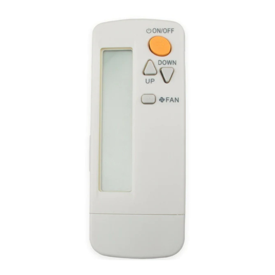
B R C 7 F 6 3 4 F (fo r He a t P u m p )
B R C 7 F 6 3 5 F (fo r C o o lin g On ly )
T h e sa me op era tion mod es a nd setting s a s w ith w ired remote c ontrollers a re p ossib le.
A lig h t rec eiv er u nit for a Ceiling M ou nted Ca ssette (R ou nd F low ) typ e is mou nted into th e ind oor u nit.
T h is u nit su p p orts th e th ree-sp eed a irflow ra te c ontrol (H H / H / L ).
2.3 .2
F u n c tio n
Control Systems
M od el
B R C7 F 6 3 4 F /6 3 5 F
O N /O F F
T emp . setting
A ir flow ra te setting
A ir flow d irec tion setting
T imer setting
M od e setting
F ilter sig n reset
Insp ec tion/T est op era tion
R e m o te C o n tr o lle r (W ir e le s s T y p e )
Sig na l rec eiv er u nit c a n
b e insta lled on th e p a nel
Sig na l rec eiv er u nit
(Insta lled typ e)
P ossib le
P ossib le
P ossib le
P ossib le
P ossib le
P ossib le
P ossib le
P ossib le
2
4 7
Advertisement

Subscribe to Our Youtube Channel
Related Manuals for Daikin BRC7E61W


Summary of Contents for Daikin BRC7E61W
- Page 1 OH08-1 R e m o te C o n tr o lle r (W ir e le s s T y p e ) B R C 7 F 6 3 4 F / B R C 7 F 6 3 5 F (F o r F X F Q -P ) 2.3 .1 F e a tu re s B R C 7 F 6 3 4 F (fo r He a t P u m p )
- Page 2 Remote Controller (Wireless Type) OH08-1 2.3.3 D imensions • RE MOTE CONTROLLE R D IME NSIONS • RE CE IV E R INSTALLATION PROCE D U RE TRANSMITTING PART RE CE IV E R RE FRIG E RANT PIPING SID E D RAIN PIPING 1 7.5 SID E...
-
Page 3: Table Of Contents
OH08-1 Remote Controller (Wireless Type) 2.3.4 Operation M anual N ames and Functions of th e Operating S ection ON OFF DOWN ON OFF TEMP TIME DOWN RESERVE CANCEL TIMER TEST MODE SWING TEST TEST COOL /HEA T CHA N G EOV ER REM OTE CON TROL S WITCH Control Systems... - Page 4 Remote Controller (Wireless Type) OH08-1 See Fig. 1, 2 DISPLAY “ ” (SIGNAL TRANSMISSION) This lights up when a signal is being transmitted. DISPLAY “ ” “ ” “ ” “ ” “ ” (OPERATION MODE) This display shows the current OPERATION MODE. For cooling only type, “ ”...
- Page 5 OH08-1 Remote Controller (Wireless Type) FAN/AIR CONDITIONING SELECTOR SWITCH Set the switch to “ ” (FAN) for FAN and “ ” (A/C) for HEAT or COOL. COOL/HEAT CHANGEOVER SWITCH Set the switch to “ ” (COOL) for COOL and “ ”...
-
Page 6: Remote Controller
In case the remote controller is not used for a long time take out all batteries in order to prevent liquid leak of the battery. IN THE CASE OF CENTRALIZ ED CONTROL SYSTEM If the indoor unit is under centraliz ed control, it is necessary to switch the remote controller’s setting. In this case, contact your DAIKIN dealer. Control Systems... - Page 7 Operation Procedure Refer to figure 1 on page 49 Operating procedure varies with heat pump type and cooling only type. Contact your Daikin dealer to confirm your system type. To protect the unit, turn on the main power switch 6 hours before operation.
- Page 8 Remote Controller (Wireless Type) OH08-1 ON OFF ON/OFF Press ON/OFF button. OPERATION lamp lights up or goes off and the system starts or stops OPERATION. NOTE Do not turn OFF power immediately after the unit stops. Then, wait no less than 5 minutes. Water is leaking or there is something else wrong with the unit.
- Page 9 OH08-1 Remote Controller (Wireless Type) Heating capacity & Outdoor air temperature Heating capacity drops as outdoor air temperature lowers. If feeling cold, use another heater at the same time as this air conditioner. Hot air is circulated to warm the room. It will take some time from when the air conditioner is first started until the entire room becomes warm.
- Page 10 AIR FLOW DIRECTION ADJUST UP AND DOWN DIRECTION The movable limit of the flap is changeable. Contact your Daikin dealer for details. Up and down adjustment Press the AIR FLOW DIRECTION ADJUST button to select the air direction as shown below.
-
Page 11: Down Fan
OH08-1 Remote Controller (Wireless Type) TIMER TIMER MODE START/STOP Press the TIMER MODE START/STOP button several times and select the mode on the display. The display flashes. For setting the timer stop ..“ ” For setting the timer start ..“ ”... - Page 12 Remote Controller (Wireless Type) OH08-1 (5) How to Set Master Remote Controller (For VRV System) When the system is installed as shown below, it is necessary to designate the master remote controller. For Heat pump system When one outdoor unit is connected with several indoor units. Outdoor unit Indoor unit One of these remote controllers needs...
- Page 13 OH08-1 Remote Controller (Wireless Type) MODE Continuously press the OPERATION MODE SELECTOR button for 4 seconds. The displays showing “ ” of all slave indoor unit connected to the same outdoor unit or BS unit flash. MODE Press the OPERATION MODE SELECTOR button to the indoor unit that you wish to designate as the master remote controller.
- Page 14 Remote Controller (Wireless Type) OH08-1 NOTE Contact your Daikin dealer in case of changing the combination or setting of group control and two remote controller control systems. Not Malfunction of the Air Conditioner The following symptoms do not indicate air conditioner malfunction I.
- Page 15 OH08-1 Remote Controller (Wireless Type) When the air conditioner stops in emergency, the run lamp on the indoor unit starts blinking. Take the following steps yourself to read the malfunction code that appears on the display. Contact your dealer with this code.
-
Page 16: Timer
Remote Controller (Wireless Type) OH08-1 MODE Reset of the display Press OPERATION MODE SELECTOR BUTTON to get the display back to the normal state. ON OFF TEMP TIME CODE DOWN RESERVE CANCEL UNIT N TIMER MODE SWING /TEST II. IN CASE BESIDES EMERGENCY STOP 1. - Page 17 OH08-1 Remote Controller (Wireless Type) [Trouble] The RUN lamp of the indoor unit is flashing and the unit does not work at all. Malfunction Code Unit No. which sensed trouble ON OFF TEMP TIME CODE DOWN RESERVE CANCEL UNIT N TIMER MODE SWING...
- Page 18 Remote Controller (Wireless Type) OH08-1 2.3.5 Installation Safety Precautions Please read these “SAFETY PRECAUTIONS” carefully before installing air conditioning unit and be sure to install it correctly. After completing installation, conduct a trial operation to check for faults and explain to the customer how to operate the air conditioner and take care of it with the aid of the operation manual.
- Page 19 OH08-1 Remote Controller (Wireless Type) Remote Controller Installation NOTES Do not throw the remote controller or impose large shocks. Also, do not store where it may be exposed to moisture or direct sunlight. When operating, point the transmitting part of the remote controller in the direction of the receiver. The direct transmitting distance of the remote controller is approximately 7 meters.
-
Page 20: Mode
Remote Controller (Wireless Type) OH08-1 (2) Setting the address of wireless remote controller (It is factory set to “ 1 ” ) Setting from the remote controller 〈 〉 ON OFF 1. Hold down the button and the /TEST button for at least 4 seconds to get the Field Set Mode mode. - Page 21 OH08-1 Remote Controller (Wireless Type) Installation of the Transmission 1. Remove the lid of the terminal box as described in the Installation Manual supplied with the indoor unit. 2. Fix the transmission at the bottom of the bell mouths on the indoor unit body using provided transmission fixing screws as shown below.
- Page 22 Remote Controller (Wireless Type) OH08-1 Installation of the Receiver 1. Remove the corner decoration lid of the decoration panel, locating at the opposing corner of the drain piping section. The lid will be no longer in use. Be sure to install the receiver to this corner. 2.
-
Page 23: Swing
OH08-1 Remote Controller (Wireless Type) (Example) If the time to clean air filter is set to “Filter Contamination-Heavy”, set Mode No. to “10”, FIRST CODE NO. to “0”, and SECOND CODE NO. to “02”. FIRST SECOND CODE NO. NOTE) MODE CODE DESCRIPTION OF SETTING Filter Contamination-...
Need help?
Do you have a question about the BRC7E61W and is the answer not in the manual?
Questions and answers