
Related Manuals for Daikin BRC7E830


Summary of Contents for Daikin BRC7E830
- Page 1 INSTALLATION MANUAL Wireless Remote Controller Kit MODEL: BRC7E830 English READ THESE INSTRUCTIONS CAREFULLY BEFORE INSTALLATION. KEEP THIS MANUAL IN A HANDY PLACE FOR FUTURE REFERENCE. 3P155845-5H...
-
Page 2: Table Of Contents
BRC7E830 Wireless Remote Controller Kit Installation manual CONTENTS 1. SAFETY CONSIDERATIONS ..................1 2. BEFORE INSTALLATION.................... 2 3. REMOTE CONTROLLER INSTALLATION ..............2 4. RECEIVER INSTALLATION ..................3 5. FIELD SETTING ......................7 6. TEST RUN ........................9 1. SAFETY CONSIDERATIONS Please read these “SAFETY CONSIDERATIONS”... -
Page 3: Before Installation
• If both this kit and fresh air intake kit are installed, only one duct chamber shall be used. Refer to the installation manual of the fresh air intake kit. 2. BEFORE INSTALLATION ACCESSORIES Check if the following accessories are included with your unit. Tapping screw for Wireless remote Remote Name Receiver Transmitter board transmitter board controller controller holder Quantity 1 set. -
Page 4: Receiver Installation
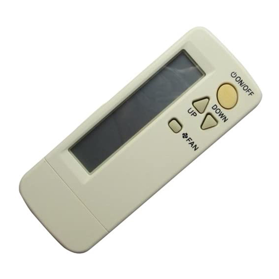
• How to insert the batteries 1. Open the back cover of the remote controller by sliding it in the direction of the arrow. 2. Insert the attached dry cell batteries. Properly insert, set the batteries by matching the (+) and (–) polarity marks as indicated. Then close the cover as before. - Page 5 SETTING PROCEDURE 1. Setting the receiver Set the wireless address switch (SS2) on the transmitter board according to the table below. Unit No. No. 1 No. 2 No. 3 Wireless address switch (SS2) When using both a wired and a wireless remote controller for 1 indoor unit, the wired controller should be set to MAIN.
- Page 6 Multiple settings A/b When the indoor unit is operated by outside control (central remote controller, etc.), it sometimes does not respond to ON/OFF and temperature setting commands from this remote controller. Check what setting the customer wants and make the multiple setting as shown below. Remote controller Movement when the operation is controlled by the other air conditioners and equipment...
- Page 7 3. Attach the decoration panel to the indoor unit. (Refer to the installation manual attached to the decoration panel.) 4. Connect the harness from the receiver to the connector X1A on the transmitter board. After connecting, use the attached clamp to fix the two harnesses to the transmitter board box. Clamp 5.
-
Page 8: Field Setting
6. Connect the harness from the transmitter board to the connector X23 or X24 on the indoor unit PC board. Be sure to pass only the harness connecting to the indoor unit PC board under the tab. Be sure to wire the harness as shown to avoid the harness to be caught by the control box and the control... - Page 9 (Example) If the time to clean air filter is set to “Filter Contamination-Heavy”, set Mode No. to “10”, FIRST CODE NO. to “0”, and SECOND CODE NO. to “02”. FIRST SECOND CODE NO. NOTE) MODE CODE DESCRIPTION OF SETTING Filter Contamination- Heavy/Light (Setting for spacing time of display time...
-
Page 10: Test Run
6. TEST RUN • Perform test run according to the instructions in the installation manual attached to the indoor unit. • After refrigerant piping, drain piping, and electric wiring, operate according to the table to protect the unit. [PRECAUTIONS] 1. Refer to malfunction code of installation manual attached to the indoor unit, if it does not operate. 2. - Page 11 3P155845-5H English...
- Page 12 3P155845-5H EM12A032 (1211) DE...
Need help?
Do you have a question about the BRC7E830 and is the answer not in the manual?
Questions and answers