Table of Contents
Advertisement
Quick Links
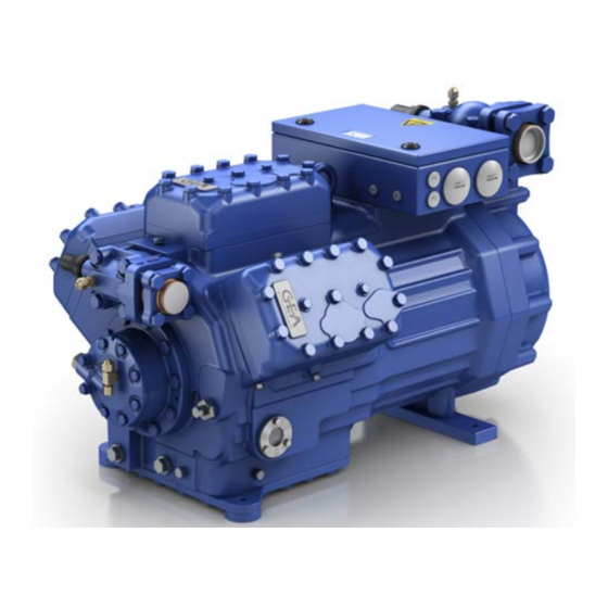
GEA Compressor HG76e
Assembly instructions
HG76e/1620-4
HG76e/1860-4
HG76e/2110-4
HG76e/2500-4
engineering for a better world
HG76e/1620-4 S
HG76e/1860-4 S
HG76e/2110-4 S
HG76e/2500-4 S
HGX76e/1620-4
HGX76e/1860-4
HGX76e/2110-4
HGX76e/2500-4
HGX76e/1620-4 S
HGX76e/1860-4 S
HGX76e/2110-4 S
HGX76e/2500-4 S
1
D
GB
F
E
I
Ru
Advertisement
Table of Contents

Related Manuals for GEA HG76e/1620-4


Summary of Contents for GEA HG76e/1620-4
- Page 1 GEA Compressor HG76e Assembly instructions HG76e/1620-4 HG76e/1620-4 S HGX76e/1620-4 HGX76e/1620-4 S HG76e/1860-4 HG76e/1860-4 S HGX76e/1860-4 HGX76e/1860-4 S HG76e/2110-4 HG76e/2110-4 S HGX76e/2110-4 HGX76e/2110-4 S HG76e/2500-4 HG76e/2500-4 S HGX76e/2500-4 HGX76e/2500-4 S engineering for a better world...
- Page 2 Observe the safety instructions contained in these instructions. These instructions must be passed onto the end customer along with the unit in which the compres- sor is installed. Manufacturer GEA Bock GmbH 72636 Frickenhausen Contact GEA Bock GmbH Benzstraße 7...
-
Page 3: Table Of Contents
Contents Page Safety 1.1 Identification of safety instructions 1.2 Qualifications required of personnel 1.3 General safety instructions 1.4 Intended use Product description 2.1 Short description 2.2 Name plate 2.3 Type key Areas of application 3.1 Refrigerants 3.2 Oil charge 3.3 Limits of application Compressor assembly 4.1 Storage and transport 4.2 Setting up 4.3 Pipe connections 4.4 Pipes... -
Page 4: Safety
1| Safety 1.1 Identification of safety instructions DANGER Indicates a dangerous situation which, if not avoided, will cause immediate fatal or serious injury. WARNING Indicates a dangerous situation which, if not avoided, may cause fatal or serious injury. CAUTION Indicates a dangerous situation which, if not avoided, may cause fairly severe or minor injury. -
Page 5: General Safety Instructions
The compressor may not be used in potentially explosive environments! These assembly instructions describe the standard version of the compressor named in the title man- ufactured by GEA. GEA refrigerating compressors are intended for installation in a machine (within the EU according to the EU Directives 2006/42/EC Machinery Directive, 97/23/EC Pressure Equipment Directive). -
Page 6: Product Description
2| Product description 2.1 Short description • Semihermetic six-cylinder reciporating compressor with oil pump lubrication. • The stream of coolant sucked out of the evaporator flows over the motor and cools it intensively. In this way, the motor can be kept at a relatively low temperature level, particularly under high loads. Suction Terminal box shut-off valve Transport eyelet Cylinder cover Valve plate... -
Page 7: Type Key
2| Product description 2.2 Name plate (example) GEA Bock GmbH 72636 Frickenhausen, Germany 380-420 Y/YY HGX76e/2500-4 AV12345-A001 440-480 Y/YY 107,0 A Y: 268,0 A YY: 412,0 A IP 65 SE 55 Fig. 2 Type designation Voltage, circuit, frequency 50 Hz Machine number Nominal rotation speed... -
Page 8: Areas Of Application
3| Areas of application 3.1 Refrigerants • HFKW / HFC: R134a, R404A/R507, R407C, R407F • (H)FCKW / (H)CFC: 3.2 Oil charge The compressors are filled at the factory with the following oil type: - for R134a, R404A/R507, R407C, R407F FUCHS Reniso Triton SE 55 - for R22 FUCHS Reniso SP 46 Compressors with ester oil charge (FUCHS Reniso Triton SE 55) are marked with an X in the type designation (e.g. - Page 9 R134a R407C 3| Areas of application t (°C) t (°C) Evaporation temperature (°C) R134a Condensing temperature (°C) <20K Suction gas superheat (K) t +20°C Suction gas temperature (°C) t +20°C R407C t (°C) 12,5 Fig. 4 R407C t (°C) R407F t (°C) Unlimited application range...
- Page 10 t (°C) t (°C) R407F 3| Areas of application <20K t (°C) t (°C) <20K <20K t +20°C t +20°C t (°C) 12,5 <20K t +20°C t +20°C t (°C) 12,5 R404A/R507 Fig. 7 t (°C) R404A/R507 t (°C) R404A/R507 <20K t +20°C t (°C)
-
Page 11: Compressor Assembly
4| Compressor assembly INFO New compressors are factory-filled with inert gas (3 bar nitrogen). Leave this service charge in the compressor for as long as possible and prevent the ingress of air. Check the compressor for transport damage before starting any work. 4.1 Storage and transport Storage at (-30°C) - (+70°C), maximum permissible relative humidity 10% - 95%, no condensation Do not store in a corrosive, dusty, vaporous atmosphere or in a com- bustible environment. -
Page 12: Pipe Connections
4| Compressor assembly 4.3 Pipe connections ATTENTION Damage possible. Superheating can damage the valve. Remove the pipe supports from the valve for soldering. Only solder using inert gas to inhibit oxidation products (scale). The discharge gas connection can be moved upwards with an adapter (accessory). -
Page 13: Laying Suction And Pressure Lines
4| Compressor assembly Solenoid valve dead Non-return valve open Fig. 17 Important: Start unloader may only be employed during the starting phase. Check the solenoid valve and the non-return valve regulary for tightness. In addition, we recommend to use a heat protection thermostat on the discharge side of the com- pressor. -
Page 14: Operating The Shut-Off Valves
4| Compressor assembly 4.7 Operating the shut-off valves Before opening or closing the shut-off valve, release the valve spindle seal by approx. ¼ of a turn counter-clockwise. After activating the shut-off valve, re-tighten the adjustable valve spindle seal clockwise. release tighten Valve spindle seal Fig. -
Page 15: Electrical Connection 15 D
5| Electrical connection Electrical connection DANGER Risk of electric shock! High voltage! Only carry out work when the electrical system is disconnected from the power supply! ATTENTION When attaching accessories with an electrical cable, a minimum bending radius of 3 x the cable diameter must be maintained for laying the cable. -
Page 16: Standard Motor, Design For Direct Or Part Winding Start
5| Electrical connection 5.2 Standard motor, design for direct or part winding start Designation on the name plate Sticker on the terminal box Y/YY Y / YY ( PW ) Compressors with this marking are suitable for direct or partial winding start. The motor winding is subdivided into two parts: Part winding 1 = 50% and part winding 2 = 50%. - Page 17 5| Electrical connection The motor is wired for direct start (YY) at the factory. For part winding start Y/YY the bridges must be removed and the motor feed line connected according to the circuit diagram: 400 V Direktstart YY Teilwicklungsstart Y/YY Direct start YY Part winding start Y/YY ATTENTION Failure to do this results in opposed rotary fields and results in...
-
Page 18: Basic Circuit Diagram For Part Winding Start With Standard Motor
5.3 Basic circuit diagram for part winding start with standard motor FC1.2 FC1.1 I> I> I> I> I> I> FC1.1 FC1.2 X SS B1 B2 Y/YY OG OG INT69 Compressor terminal box Anschlußkasten Verdichter Fig. 23 Oil differential pressure monitor High pressure safety monitor Safety chain (high/low pressure monitoring) Release switch (thermostat ) - Page 19 L1.1 L2.1 L3.1 L1.2 P> P-Öl FC1.2 Motor protection switch (part winding 2) Control power circuit fuse KF1T Delay relay max. 1s Main switch 5HGZ76e.7 Mains contactor (part winding 1) 5HGZ76e.7 Mains contactor (part winding 2) 6HG76e.7 Control voltage switch Terminal strip in the external switch cabinet 5HGZ76e PW INT69...
-
Page 20: Special Motor: Design For Direct Or Star-Delta Start
5| Electrical connection 5.4 Special motor: design for direct or star-delta start Designation on the name plate Sticker on the terminal box ∆ / Y... - Page 21 ∆ / Y ∆ / Y ∆ / Y 5| Electrical connection Stern-Dreieck-Anlauf ist nur im Spannungsbereich ∆ (230 V) möglich. Beispiel: Stern-Dreieck-Anlauf ist nur im Spannungsbereich ∆ (230 V) möglich. Beispiel: Stern-Dreieck-Anlauf ist nur im Spannungsbereich ∆ (230 V) möglich. Beispiel: Star-delta start-up is only possible for 230 V power supply.
-
Page 22: Circuit Diagram For Star-Delta Start 230 V ∆ / 400 V Y
5.5 Circuit diagram for star-delta start 230 V ∆ / 400 V Y FC1.2 FC1.1 I> I> I> I> I> I> FC1.1 FC1.2 X SS B1 B2 ˜ OG OG INT69 Compressor terminal box Anschlußkasten Verdichter Fig. 24 Oil differential pressure monitor High pressure safety monitor BT2.X Thermal protection thermostat... - Page 23 L1.1 L2.1 L3.1 L1.2 P> P-Öl Control power circuit fuse KF4T Delay relay for contactor changeover Main switch Mains contactor ∆-contactor 5HG76e.8 Y-contactor 5HGZ76e.7 Control voltage switch Terminal strip in the external switch cabinet D/S INT69 6HG76e BOCK COMPRESSORS 6HG76e...
-
Page 24: Electronic Trigger Unit Int69 G
5| Electrical connection 5.6 Electronic trigger unit INT69 G The compressor motor is fitted with cold conductor temperature sensors (PTC) connected to the electronic trigger unit INT69 G in the terminal box. In case of excess temperature in the motor winding, the INT 69 G deactivates the motor contactor. -
Page 25: Function Test Of The Trigger Unit Int69 G Ru
5| Electrical connection 5.8 Function test of the trigger unit INT69 G Before commissioning, after troubleshooting or making changes to the control power circuit, check the functionality of the trigger unit. Perform this check using a continuity tester or gauge. Relay position INT69 G Gauge state Relay position... -
Page 26: Commissioning
6 | Commissioning 6.1 Preparations for start-up INFO To protect the compressor against inadmissible operating conditions, high pressure and low pressure pressostats are mandatory on the installation side. The compressor has undergone trials in the factory and all functions have been tested. There are therefore no special running-in instructions. -
Page 27: Evacuation
6 | Commissioning 6.4 Evacuation ATTENTION Do not start the compressor if it is under vacuum. Do not apply any voltage - even for test purposes (must only be operated with refrigerant). Under vacuum, the spark-over and creepage current distances of the terminal board connection bolts shorten;... -
Page 28: Start-Up
6 | Commissioning 6.6 Start-up WARNING Ensure that both shut-off valves are open before starting the compressor! Check that the safety and protection devices (pressure switch, motor protection, electrical contact protection measures, etc.) are all functioning properly. Switch on the compressor and allow to run for a minimum of 10 min. Check the oil level by: The oil must be visible in the sightglass. -
Page 29: Maintenance
2500-4 (S) Designation Item No. Item No. Item No. Item No. Set of gaskets kit 81241 81242 81243 Valve plate kit 81240 81040 81041 Oil pump kit 80116 Oil sump heater kit (220-240 V) 08426 Only use genuine GEA spare parts! -
Page 30: Extract From The Lubricants Table
7.4 Extract from the lubricants table The oil type filled as standard in the factory is marked on the name plate. This oil type should be used as a preference. Alternatives are stated in the extract from our lubricants table below. Refrigerants GEA standard oil types Recommended alternatives Fuchs Reniso Triton SEZ 32 HFKW... -
Page 31: Accessories
8| Accessories 8.1 Capacity regulator ATTENTION If the capacity regulator is mounted at the factory, the control com- ponent (pilot valve) is mounted and connected subsequently by the customer. If the control component is not connected, the cylinder bank is switched off permanently. Damage to the compressor is possible! LR 1 LR 2 Cover... -
Page 32: Oil Separator
Information about the use, operation, maintenance and servicing of the components is available in the printed literature or on the internet under www.gea.com 8.2 Oil separator ATTENTION Oil slugging can result in damage to the compressor. -
Page 33: Technical Data
9| Technical data Oil charge Weight 380-420 V Y/YY - 3 - 50 Hz PW 440-480 V Y/YY - 3 - 60 Hz PW PW = Part Winding Winding ratio : 50% / 50% No. of cylinders... -
Page 34: Dimensions And Connections
Oil drain HG76e/1620-4 14844 HG76e/1860-4 14846 HG76e/2110-4 14848 HG76e/2 Stopfen Ölfüllung HG76e/1620-4 S 14845 HG76e/1860-4 S 14847 HG76e/2110-4 S 14849 HG76e/2 Oil charge plug HGX76e/1620-4 14852 HGX76e/1860-4 14854 HGX76e/2110-4 14856 HGX76e/ Anschluss Ölsumpfheizung... - Page 35 10| Dimensions and connections Suction line see technical data, Chapter 9 Discharge line Connection suction side, not lockable 8 “ NPTF Connection suction side, lockable 16 “ UNF Connection suction side, not lockable 4 “ NPTF Connection discharge side, not lockable 8 “...
-
Page 36: Declaration Of Installation
European Union (in accordance with Machinery Directive 2006/42/EC) The manufacturer: GEA Bock GmbH, Benzstraße 7 72636 Frickenhausen, Tel.: 07022/9454-0 hereby declares that the refrigerating compressor HG76e complies with the basic requirements of Appendix II 1B of the Machinery Directive 2006/42/EC. -
Page 37: Service
12 | Service Dear customer, GEA compressors are top-quality, reliable and service-friendly quality products. If you have any questions about installation, operation and accessories, please contact our technical service or specialist wholesaler and/or our representative. The GEA service team can be contacted by phone with a toll-free hotline 00 800 / 800 000 88 or via e-mail: refrigeration@gea.com Yours faithfully GEA Bock GmbH Benzstraße 7... - Page 38 • • GEA Group is a global engineering company with multi-billion euro sales and operations in more than 50 countries. Founded in 1881, the company is one of the largest providers of innovative equipment and process technology. GEA Group is listed in the STOXX Europe 600 index.
Need help?
Do you have a question about the HG76e/1620-4 and is the answer not in the manual?
Questions and answers