Table of Contents
Advertisement
Quick Links
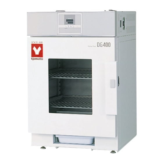
Instrument Drying Oven
Model DG400
Instruction Manual
● Thank you very much for purchasing this Yamato
DG400 instrument drying oven.
● Please
read
the
"Warranty" before operating this unit to assure
proper operation. After reading these documents, be
sure to store them securely together with the
"Warranty" at a handy place for future reference.
Warning
:Before operating the unit, be sure to
read
important warnings
instructions.
Yamato Scientific America Inc.
Santa Clara,CA
First edition
"Operating
Instructions"
carefully
and
fully
in
This paper has been printed on recycled paper
and
understand
the operating
Advertisement
Table of Contents

Related Manuals for Yamato DG-450C


Summary of Contents for Yamato DG-450C
- Page 1 Instrument Drying Oven Model DG400 Instruction Manual First edition ● Thank you very much for purchasing this Yamato DG400 instrument drying oven. ● Please read “Operating Instructions” “Warranty” before operating this unit to assure proper operation. After reading these documents, be sure to store them securely together with the “Warranty”...
-
Page 3: Table Of Contents
Table of contents 1.Safety precautions ..............1 Explanation of pictograms ............. 1 List of symbols ............... 2 Warning・Cautions ..............3 2. Before operating the unit ............4 Precautions when installing the unit ............. 4 Installation procedures・precautions ............ 7 3. Names and functions of parts ............9 Main body ................ -
Page 4: Safety Precautions
1. Safety precautions Explanation of pictograms About pictograms A variety of pictograms are indicated in this operating instruction and on products for safe operation. Possible results from improper operation ignoring them are as follows. Be sure to fully understand the descriptions below before proceeding to the text. -
Page 5: List Of Symbols
1. Safety precautions List of symbols Warning Danger!: High Danger!: High Danger!: Moving Danger!: Hazard General warnings voltage temperature part of explosion Caution Caution for no Caution for water General cautions Electrical shock! Burning! liquid heating! leak! Poisonous For water only material Prohibitions Do not... -
Page 6: Warning・Cautions
1. Safety precautions Warning・Cautions Warning Never operate the unit in an atmosphere containing flammable or explosive gas Never operate the unit in an atmosphere containing flammable or explosive gas. Otherwise, an explosion or a fire may result since the unit is not explosion-proof. See section “13. -
Page 7: Before Operating The Unit
2. Before operating the unit Precautions when installing the unit 1. Carefully select an installation site. Take special care not to install the unit at a place described below: ・ Uneven surfaces or dirty surfaces ・ Where flammable gas or corrosive gas exists ・... - Page 8 2. Before operating the unit Precautions when installing the unit 4. Secure sufficient ventilation for the unit. Do not operate the unit when its side panels and vent holes are blocked. Internal temperature of the unit will rise degrading the performance and an accident, a malfunction or a fire may result.
- Page 9 2. Before operating the unit Precautions when installing the unit 7. Be sure to connect the power plug to the dedicated power distribution panel or a wall outlet. Use a power distribution panel or a wall outlet that meets the electrical capacity of the unit. Electrical capacity: DG400 AC220V...
-
Page 10: Installation Procedures・Precautions
2. Before operating the unit Installation procedures・precautions (1) Select an installation site. ・Make sure that all of four legs are securely on a flat surface. ・Two legs on the unit front are adjustable. Adjust them so that the installed unit will not be unstable. - Page 11 2. Before operating the unit Installation procedures・precautions (4) Take special care for instruments shown below: ①Instruments that contain flammable or explosive components or such instruments to which samples containing those components are attached. ・The unit is not explosion proof. Never attempt to dry or process instruments to which samples that contain flammable or explosive components are attached.
-
Page 12: Names And Functions Of Parts
3. Names and functions of parts Main body Front panel of DG400 Operation panel Standalone overheat preventive device (hydraulic) Observation window Rating sticker Door Drain pan Aadjusters(2 points) Shelf board (One of the shelf boards is fixed on the lowest stage of the shelfpeg pillars) Rear panel of DG400 Exhaust ports Power cord... -
Page 13: Operation Panel
3. Names and functions of parts Operation panel MEASURED TEMP. ⑥ ⑤ ℃ ⑦ ④ HEATER SET TEMP. ③ ① TIMER STOP SUB MENU ② Name Operation/action ① RUN/STOP key Used for starting/stopping operation. ② ▼▲ keys Used for selecting settings. ③... -
Page 14: Explanation Of Characters
3. Names and functions of parts Explanation of characters Characters on the controller are explained in this section. Characters Identifier Name Application AStP Auto stop setting Used for setting auto stop operation. AStr Auto start setting Used for setting auto start operation. Displayed when timer operation has Time up ended. -
Page 15: Operating Procedures
4. Operating procedures List of operation modes and functions Operation modes of the unit are as shown below: № Name Description Page Turning the ELB on to enter the operation setting mode. Proceed to temperature setting that uses ▼▲ keys. Fixed temperature P.16 operation... - Page 16 4. Operating procedures List of operation modes and functions Functions of the unit are as shown below: № Name Description Page Automatic overheat prevention function: This function is linked to the unit set temperature and has been set to so that it is automatically activated (returned automatically) at a temperature 12℃...
-
Page 17: Operation Mode・Function Setting Keys And Characters
4. Operating procedures Operation mode・function setting keys and characters Key operations and characters in the diagram below are used for operation mode and function settings. ELB ON Fixed temp. Timer Functional operation operaiton setting Long TIMER press MENU Temperature setting ▲... -
Page 18: Operating Procedures (Settings For Overheat Prevention Device)
4. Operating procedures Operating procedures (settings for overheat prevention device) As a safety measure for preventing overheat, a hydraulic overheat prevention device (manual return) is installed. Temperature setting range and functions The temperature setting range for the standalone overheat prevention device is “50℃~120℃.” When the temperature in the bath keeps rising beyond the controller set temperature and reaches the set temperature of the overheat prevention device, controller power is shut off. -
Page 19: Operating Procedures (Fixed Temperature Operation)
4. Operating procedures Operating procedures (fixed temperature operation) 1.Turn the ELB ON. (Turn the ELB to “ON.”) How to start fixed temperature operation When the ELB is turned ON, the initial values will be displayed for about four seconds, then the initial screen will appear and the current bath temperature and the previous set temperature are displayed on each of the indicators. -
Page 20: Operating Procedures (Quick Auto Stop Operation)
4. Operating procedures Operating procedures (quick auto stop operation) Used when you want to “stop fixed temperature operation being performed automatically in several hours. Quick auto stop operation is a function to enable auto stop timer setting during operation. Procedures for quick auto 1. - Page 21 4. Operating procedures Operating procedures (quick auto stop operation) When you want to change settings, press the ▼▲ keys on When you want to correct set temperature or set time, the current screen to enter the setting mode where you can or change settings change settings.
-
Page 22: Operating Procedures (Auto Stop Operation)
4. Operating procedures Operating procedures (auto stop operation) This mode automatically stops fixed value operation after a certain time from its start set with the timer. Procedures for auto stop 1. Setting a stop time ① After confirming the temperature you want is set, press operation the TIMER key to display characters AStP the measured temperature screen that indicate auto... - Page 23 4. Operating procedures Operating procedures (auto stop operation) When you want to change settings, press the ▼▲ keys on When you want to correct set temperature or set time, the current screen to enter the setting mode where you can or change settings change settings.
-
Page 24: Operating Procedures (Auto Start Operation)
4. Operating procedures Operating procedures (auto start operation) This mode automatically starts fixed value operation after a certain time from its start set with the timer. However, operation does not stop automatically but needs to be stopped manually. Procedures for auto start 1. - Page 25 4. Operating procedures Operating procedures (auto start operation) When you want to When you want to change the set temperature during timer counting, press the ▼▲ keys during that status to switch the set temperature correct set temperature or set screen to the set temperature input mode, which blinks to enable change of the set temperature with the ▼▲...
-
Page 26: Useful Functions (Calibration Offset Function)
4. Operating procedures Useful functions (calibration offset function) Calibration offset function compensates any differences Using the calibration offset between the target temperature in the bath and the control function temperature of the controller (sensor temperature.) The function can compensate in parallel to either plus or minus side for the whole temperature band of the unit. -
Page 27: Useful Function (Setting Lock Function)
4. Operating procedures Useful function (setting lock function) Using the lock function This function locks the set operation status. The temperature is set at “off” on shipping from the factory. ① Press the TIMER key (SUBMENU key) long to enter the sub menu mode. -
Page 28: Useful Function (Power Outage Compensation Function)
4. Operating procedures Useful function (power outage compensation function) Using the power outage The power outage compensation function returns the main compensation function unit operation to the resume status after recovery from power outage, or keeps the current stop status. The function is set at “on”... -
Page 29: Cautions On Handling
If smoke is emerges on the unit or an odd odor is felt, immediately turn the ELB on the main unit off, turn the power supply off and contact your dealer or a Yamato sales office for inspection. Otherwise, a fire or an electrical shock may result. The user shall never attempt to repair the unit to avoid any possible dangers. - Page 30 5. Cautions on handling Caution 1.Do not step on the unit. Do not step on the unit. Otherwise, the unit may trip over or be damaged resulting a personal injury or a malfunction. 2.Do not put or drop an object on the unit. 2.Do not put or drop an object on the unit.
- Page 31 5. Cautions on handling Caution 9. About installation of shelf boards and instruments Correctly place shelf boards and samples according to Installation procedures・precautions on page 7. If these are not placed correctly, the unit will be unable to perform correctly as well as an accident or a malfunction may result.
-
Page 32: Maintenance Procedures
6. Maintenance procedures Daily inspection/maintenance Be sure to perform daily inspection and maintenance to assure reliable operation of the unit. Warning ● Be sure to pull out the power cord unless necessary before trying to do inspection and maintenance works. ●... -
Page 33: When The Unit Is Not To Be Used For A Long Time Or When Disposing
7. When the unit is not to be used for a long time or when disposing When the unit is not to be used for a long time or when disposing Caution Warning When the unit is not going to be used for a long When disposing the unit ●Do not leave the unit in the area where time... -
Page 34: Troubleshooting
8. Troubleshooting Safety device and error codes The unit has the self diagnostic function with a controller and a separate safety device. Table below shows possible causes and measures when the safety device is triggered. [Error codes] When a functional or mechanical abnormality occurs, an error code will be displayed on the control panel. -
Page 35: When A Malfunction Is Suspected
8. Troubleshooting When a malfunction is suspected If any of the symptoms below occurs Symptom Check ● If the power cord is connected to the power supply securely. Turning the ELB to on will ● If power outage is occurring. not activate the unit. -
Page 36: After Sales Service And Warranty
9. After sales service and warranty When requesting a repair When requesting a repair If any trouble occurs, immediately stop operation, turn the ELB off, pull out the power plug and contact your dealer or our sales office. Information necessary for requesting a repair ●... -
Page 37: Specifications
10. Specifications Model DG400 Operating temperature range Room temperature +5℃~70℃ Inner material Stainless steel SUS304 Observation window Standard glass 3mm W250 x H300 mm Heater SUS pipe heater 1.0 kW Control system PID control with a micro computer Temperature setting / Digital display using up/down keys display system Fixed temperature operation, quick auto stop operation... -
Page 38: Wiring Diagram
11. Wiring diagram Symbol Part name Symbol Part name Thermostat ELB with an over current (Standalone overheat prevention protector device) Terminal block Temperature sensor (K) Heater CONT Planar circuit board X1, X2 Relay Display circuit board Solid state relay Transformer... -
Page 39: List Of Replacement Parts
12. List of replacement parts Components of DG400 Symbol Part name Code No. Specifications Manufacturer ― Heater 220V 1.0 kW Yamato K thermocouple Sensor 1-16-003-0049 Yamato LCK-MI-2000Y EGO thermostat LT00008745 55.13225.070 E.G.O Display circuit board LT00007639 CN40B-Y Yamato CONT Planar circuit board... -
Page 40: List Of Dangerous Materials
13. List of dangerous materials Never use an explosive substance a flammable substance or a substance containing them for this device. ① Nitroglycol, glycerine trinitrate, cellulose nitrate and other explosive nitrate esters ② Trinitrobenzen, trinitrotoluene, picric acid and other explosive nitro compounds ③... -
Page 41: Standard Installation Manual
14. Standard installation manual *Install the product according to the following: (Confirm separately for optional items or special specifications) Installation Judg Model Serial number Date Installation mgr. mgr.(company name) ment TOC No. Reference page of the Judg № Item Implementation method operating instruction manual ment Specifications... - Page 42 Be sure to use the unit strictly following the handling and operating instructions in this operating instruction. Yamato Scientific Co., Ltd. assumes no responsibility for an accident or a malfunction caused by use of this product in any way not specified in this operating instruction.
Need help?
Do you have a question about the DG-450C and is the answer not in the manual?
Questions and answers